Energy Efficiency Measures (EEMs)
1. Overview
An EP3 model holds every design alternative in one file. Global is the base model: the geometry, constructions, schedules, loads, and HVAC systems built through the rest of this handbook. An Energy Efficiency Measure (EEM) is a named alternative to Global. It stores only what it changes, such as a lighting power density, a construction, or a whole HVAC system, and takes everything else from Global or from the EEMs it builds on.
EEMs cover several kinds of work with one mechanism:
- Baseline against proposed. One EEM (or Global) holds the baseline, another the proposed design.
- Single options side by side. A few EEMs that each change one thing, such as the chiller type or the insulation level, to see each effect alone.
- A final model from separate measures. A lighting EEM, an envelope EEM, and an HVAC EEM, developed separately and combined into one EEM (§3.2).
- Parametric runs. A branching EEM holds several values of one change, and every combination of the chosen values runs as a separate simulation (§6).
- What each change contributes. Disaggregation splits the difference between two EEMs into change groups and simulates their combinations, so the share of each change in the result is known (§9).
The EEM dropdown in the top toolbar sets the active EEM: the alternative that edits are stored in and that the 3D view, the HVAC diagram, the outliners, and the dialogs show (The EP3 Interface and Model Settings). With Global selected, edits go to the base model.
Almost anything can differ by EEM: any field of any object, a value for one Space or Zone (Internal Loads, Space Types, and Zone Types), whether an object exists at all (§4.2), the construction painted on a surface (Constructions and Materials), the building’s North Axis (Creating Building Geometry), the weather file (Weather, Climate, and Design Conditions), branch connections (Air Loops, Branches, and Nodes), and the zone equipment each zone uses (Zone-Level HVAC Equipment and Zone Sizing).
Build the building in Global, and switch to an EEM only for the changes that define it; an EEM that collects unrelated edits is hard to compare. Its change list (§4.4) shows what it holds.
2. Creating an EEM
2.1 The EEM list
EEMs are managed in the main object dialog: open EP3, and under Model Settings in Column 1 choose Model Alternatives (EEMs). Column 2 lists Global first, then every EEM; Column 3 shows the selected EEM’s page.
- Add Object adds an EEM named
EEM 1,EEM 2, and so on, built on Global only. Rename it in the name box at the top of its page. - Copy EEM adds
<name> copy(<name> copy 1, and so on, when the name is taken), an independent EEM that starts out like the selected one (§3.3). It is disabled for Global, HVAC System, and SWH System; its tooltip says why. - ↑ and ↓ on a row set the order of the list, which the EEM dropdown and the parent pickers follow.
- ✕ deletes the EEM. When objects are on only in that EEM and nothing refers to them, a dialog lists them; checked objects are deleted with the EEM, and unchecked ones are kept. HVAC System and SWH System (§5.3) cannot be deleted.
2.2 The EEM page
An EEM’s page holds its settings, then its changes:
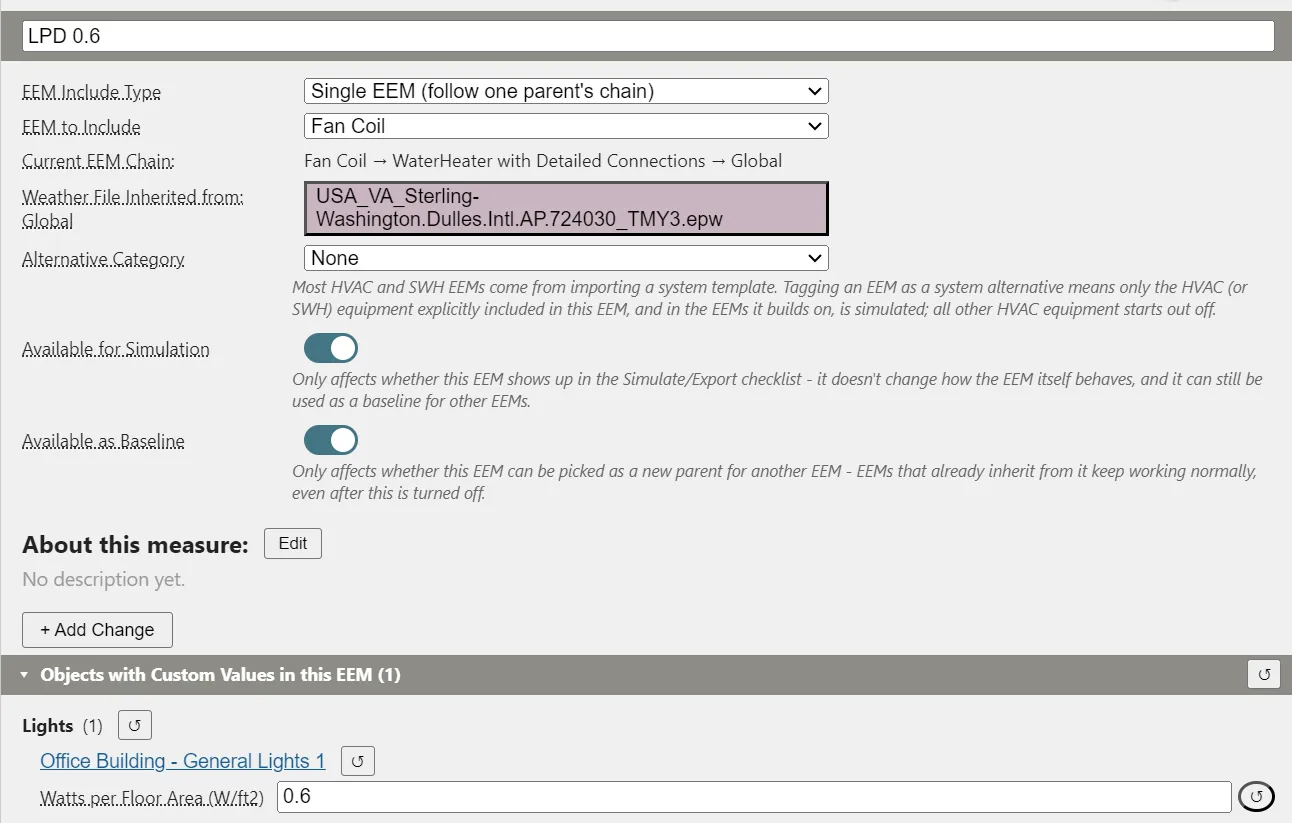
- EEM Include Type and EEM to Include or Which EEMs to Include: what the EEM builds on (§3). Current EEM Chain: lists the EEMs it resolves through, nearest first, ending at Global. A branching EEM in the chain lists the iterations this EEM includes, for example “HVAC System (Fan Coil | PSZ-AC) → Global” (§6).
- Weather File: a weather file for this EEM; click the button to choose one. Without one, the row reads Weather File Inherited from: Global and shows the model’s file.
- Alternative Category: None, HVAC System, or SWH System, which marks the EEM as a complete system alternative (§5).
- Enable Branching: shown while the EEM has no changes (§6.1).
- Available for Simulation: whether the EEM is listed in the Simulate dialog (§7). It does not change what the EEM contains or whether other EEMs can build on it.
- About this measure: a description; Edit opens it for typing and Done saves it.
- The change sections (§4.4), or a branching EEM’s iterations (§6).
3. How an EEM inherits
EEM Include Type offers two ways to build on other EEMs. In both, values stored in the EEM win, and Global supplies whatever nothing in the chain sets.
3.1 Single EEM: building on one parent
Single EEM (follow one parent’s chain) takes one parent, chosen in EEM to Include (Global or any EEM). The EEM inherits everything the parent has, including what the parent inherits, all the way to Global. A later edit to the parent, or to any EEM in its chain, reaches this EEM too. Use it to extend a line of measures, each building on the last.
3.2 Multiple EEMs: combining several
Multiple EEMs (ordered list, first has priority) takes a list of EEMs, checked in Which EEMs to Include. A new EEM starts in this mode with nothing checked, which builds on Global alone. The EEM takes only the changes each listed EEM stores itself, not what those EEMs inherit. Checked EEMs move to the top of the list, and ↑ and ↓ set their order: when two listed EEMs set the same value, the one higher in the list wins.
3.3 Copy EEM, or build on an EEM
Copy EEM makes an independent EEM that resolves exactly like the original: it copies the EEM Include Type and parents in the same order, the Weather File, Available for Simulation, the description, the Alternative Category, the original’s choices of its parents’ iterations, and every value the original stores. A branching EEM’s iterations are copied as new iterations with the same names and values, so editing or deleting an iteration of one EEM leaves the other’s alone. A copy of an EEM tagged HVAC System or SWH System adds another option to that built-in EEM (§5.3). Later edits to the original do not reach the copy, and EEMs built on the original keep building on it. An EEM built on another (Single EEM) follows its parent’s later edits. Copy an EEM to fork a variant that should not move with the original; build on it when the new measure should always include the original’s.
3.4 Worked example
Three EEMs, in IP units:
| EEM | EEM Include Type | Builds on | Change it stores |
|---|---|---|---|
| LPD | Single EEM | Global | Lights Watts per Floor Area 0.6 W/ft² |
| Insulation | Single EEM | LPD | Exterior wall insulation Thermal Resistance R-19 |
| Proposed | Multiple EEMs | Insulation | none |
Insulation’s chain is Insulation → LPD → Global, so it has both the R-19 wall and the 0.6 W/ft² lighting. Proposed lists Insulation under Multiple EEMs, so it takes only what Insulation stores, the R-19 wall:
| EEM | Watts per Floor Area | Wall insulation |
|---|---|---|
| Global | Global’s value | Global’s value |
| LPD | 0.6 W/ft² | Global’s value |
| Insulation | 0.6 W/ft² | R-19 |
| Proposed | Global’s value | R-19 |
To bring the lighting change into Proposed, check LPD in its Which EEMs to Include as well. In SI the values are 0.6 × 10.764 = 6.46 W/m² and R-19 × 0.1761 = 3.35 m²·K/W.
4. Making changes in an EEM
4.1 Editing with an EEM active
With an EEM active, every value you enter in a dialog is stored in that EEM. A field with nothing stored in the active EEM shows the value it inherits on a rose background; entering a value stores it in this EEM and removes the tint, and the field’s ↺ clears it again. EEMs that build on this one inherit the new value; other EEMs keep theirs.
The 3D view shows a change made in an EEM to a window’s size or a surface’s construction: the window’s outline pulses cyan, or the surfaces turn white and their construction pulses back in. The status bar reads Changed in EEM "<name>", not Global. Neither interrupts your work. Resetting a value to inherit, such as painting with Default, shows neither. Redo shows the change again; undo doesn’t. With the operating system’s reduced-motion setting on, the highlight shows for a second without pulsing.
To build an envelope EEM from a set of upgraded constructions in another .ep3 file, make the EEM active and use Populate Constructions in the Constructions panel (Constructions and Materials).
4.2 Switching objects on and off
An object can be switched off in an EEM. An object that is off is not exported in that EEM, and neither is anything that depends on it, such as a loop’s branches or a unit’s sub-components. Ways to switch objects:
- Include in EEM ⟨EEM name⟩?, the checkbox in Column 3 of the main object dialog, for the open object in the active EEM.
- Include Selected in EEM and Exclude Selected in EEM in Column 2, for every checked object in the active EEM (The EP3 Interface and Model Settings).
- The power button on a row of the HVAC Outliner, and on a window, shading collection, or daylight sensor row of the Building Geometry Outliner, for that object in the active EEM.
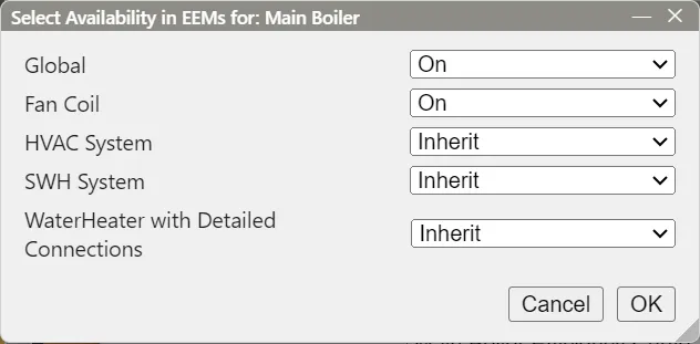
- Manage availability in EEMs, a button in Column 2 and in the Selected Object dialog, for every EEM at once. It opens Select Availability in EEMs for: with a row per EEM: On, Off, or Inherit (Global offers On and Off). When the selected objects differ in an EEM, that row also offers Do Not Change. OK applies every row in one undo step; Cancel discards them.
Objects that are off in the active EEM are hidden in the 3D view, the HVAC diagram, and both outliners. The Objects that are off in this EEM toggle in the top toolbar shows them again, so they can be switched back on.
4.3 Excluding a zone
Switching a Zone off in an EEM takes its Spaces with it: their surfaces, windows, and daylight sensors are left out of that EEM, as is every object that refers to the Zone or its Spaces. A Space has no switch; it follows its Zone. No zone equipment can be assigned to the excluded Zone, and a replicated air loop makes no copy for it. Switching the Zone back on restores everything. This is the way to model a building with and without an addition or an atrium (Spaces and Zones).
4.4 Reviewing and resetting an EEM’s changes
An EEM’s page lists everything stored in that EEM, and nothing it inherits, in collapsible sections, grouped by object type and then by object:
- Objects with Custom Values in this EEM: each field the EEM sets, as an editable row. A value set for one Space or Zone reads
Field [Space name]. - Objects Included in this EEM and Objects Excluded from this EEM: each object the EEM switches, with an Inherit / Include / Exclude choice.
- Window Sizes in this EEM: each window’s Width, Height, and Sill Height the EEM sets (Windows, Shading, and Daylighting).
Values are edited in place, in the display units. Clicking an object’s name makes this EEM active and opens the object. ↺ on a row, an object, an object type, or a section removes those values from this EEM, so they inherit again; the object type and section resets ask first.
+ Add Change adds values without opening each object. Choose an Object Type, then Objects (All or Selected only, with a filter), then Fields (Include in EEM is listed first). A row appears for each object and field with its value in this EEM; a change is stored at once. Done Adding Changes closes the picker.
5. HVAC and SWH system alternatives
5.1 System EEMs from the Model Wizard
Each HVAC system imported through the Model Wizard or the Import dialog becomes an EEM named for its template, with Alternative Category HVAC System; each service hot water system becomes an EEM with SWH System. The system’s objects are stored in Global and switched on in its EEM. A new HVAC EEM builds on the model’s service water heating EEM when there is one, so every HVAC alternative carries the water heating system (The Model Wizard). Tagging an EEM SWH System turns its Available for Simulation off, since it is a building block for the HVAC EEMs.
In an EEM with an Alternative Category, or one that builds on such an EEM, the HVAC side starts empty: only the loops, equipment, and setpoint managers that this EEM or an EEM in its chain switches on are exported. Global, with no tagged EEM in its chain, exports everything that is on.
Anything you add to the HVAC side while a system EEM is active is switched on in that EEM, so it becomes part of that system and stays off in the other alternatives (The HVAC Outliner and Creating HVAC Systems).
5.2 Changing a system
To vary one system, such as a higher fan efficiency for the fan coils, add an EEM built on that system’s EEM (Single EEM) and make the change there. Leave its Alternative Category at None: the tag marks a complete system choice, and a tagged EEM is offered as an option of the HVAC System EEM (§5.3).
5.3 Comparing systems: the HVAC System and SWH System EEMs
Every model has two built-in, read-only EEMs, HVAC System and SWH System. Each is a branching EEM (§6) whose iterations are the EEMs tagged with that category, so a new tagged EEM appears there by itself. They are not simulated themselves. To run every HVAC alternative from one EEM, add an EEM built on HVAC System: it runs once per system, each run with that system EEM’s full chain. Its Simulation Branches from Parent EEMs section switches individual systems out (§6.2). An iteration of a built-in EEM that nothing sets is included.
5.4 Combining systems that serve different zones
A building may need two systems, such as a fan coil system for the offices and a packaged unit for a server room. The Model Wizard imports each as a separate EEM. To make one design from them:
- Assign each system’s zone equipment to the zones it serves, in EP3 - Select Zone Conditioning Equipment (Zone-Level HVAC Equipment and Zone Sizing).
- Add an EEM, such as “Proposed Systems”, with Multiple EEMs and both system EEMs checked. Its Alternative Category stays None.
Multiple EEMs takes only what each listed EEM stores itself (§3.2), so also check the service water heating EEM and any other EEM whose changes the design needs.
6. Branching EEMs
A branching EEM holds several iterations of one change, such as three lighting power densities, so they need not be built as three EEMs. It targets one object type, all of its objects or a chosen set, and one or more of that type’s fields; each iteration sets values for those fields. A branching EEM is never the active EEM: it is left out of the EEM dropdown and is edited on its page.
6.1 Enabling branching and authoring iterations
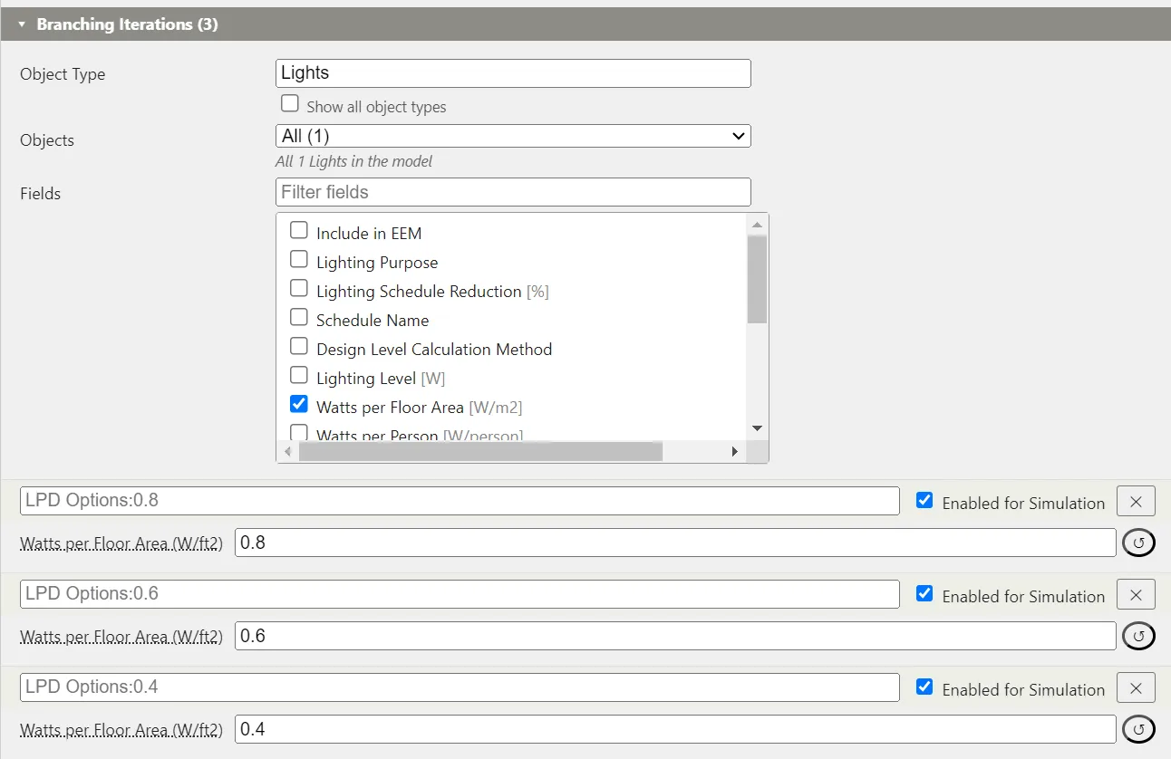
An EEM can be made branching while it stores no changes. Enable Branching asks for confirmation; there is no control to turn branching off, though Undo reverses it. The page then shows Branching Iterations:
- Choose the Object Type. Changing it later clears the objects, fields, and every iteration, and asks first when iterations have values.
- Choose the Objects: All, or Selected only.
- Choose the Fields the iterations set. Include in EEM lets an iteration switch the objects on or off.
- Click + Add Iteration for each variant and enter its values. A blank value inherits as usual.
An iteration is named <EEM>:<value> when it sets one field, such as LPD Options:0.6, or <EEM>:Option n when it sets several; typing a name replaces it. This name labels the iteration in run names and on the parallel coordinates plot. Enabled for Simulation (on for a new iteration) sets whether the iteration runs when this EEM is simulated, and is the default for EEMs built on it. ✕ deletes the iteration.
6.2 Choosing iterations in an EEM built on a branching EEM
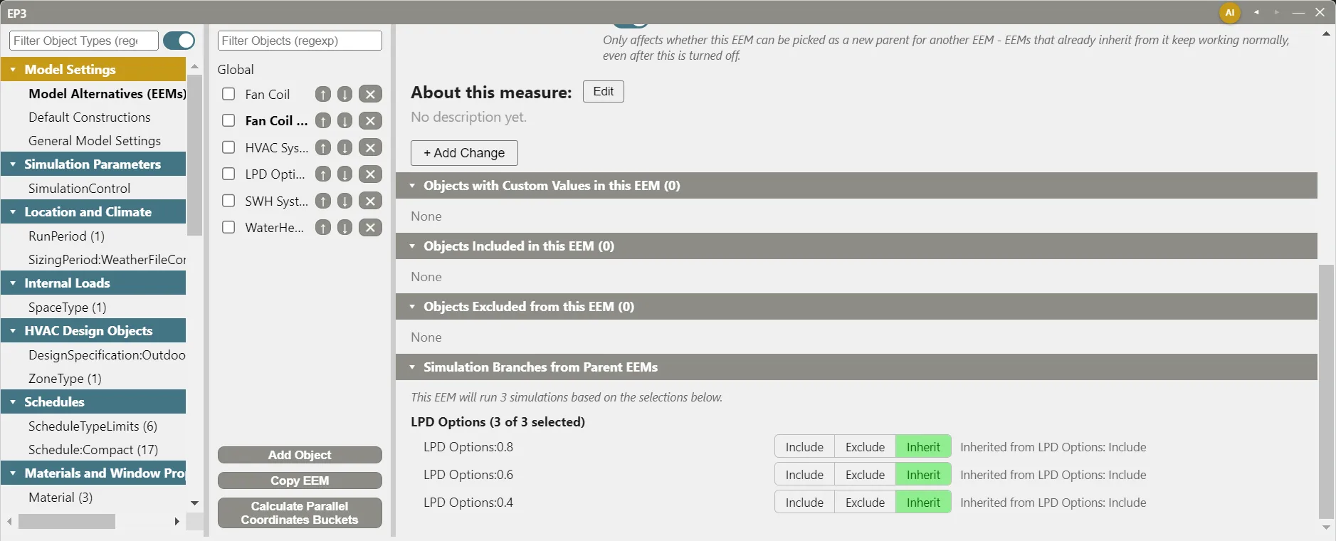
An EEM with a branching EEM in its chain shows Simulation Branches from Parent EEMs, with a group per branching EEM headed <name> (k of n selected) and a switch per iteration: Include, Exclude, or Inherit. Inherit takes the choice from the nearest EEM up the chain that sets one, which the row names; when nothing sets it, a user’s iteration is excluded and an iteration of HVAC System or SWH System is included.
6.3 Combinations
Each included iteration of each branching EEM in the chain multiplies the runs: the EEM runs once per combination. An EEM with Multiple EEMs listing HVAC System (two system EEMs in the model) and LPD Options (three iterations) runs 2 × 3 = 6 simulations. The section reads “This EEM will run 6 simulations based on the selections below”, and the EEM list shows (6 runs) after the EEM’s name; a branching EEM’s row also shows (x3 branches).
7. Choosing what gets simulated
The Simulate button in the top toolbar opens Simulate / Export, which lists every EEM, Global included, whose Available for Simulation is on. Each checked EEM runs once, or once per combination (§6.3), and the heading counts the runs chosen. More than eight runs asks for confirmation first, since each run occupies one CPU core. A branch run’s file name adds the names of the EEMs and iterations in its chain, with values in SI so the name does not change with the display units. Running Simulations covers the dialog.
8. The parallel coordinates plot
A parallel coordinates plot draws one line per run across a row of vertical axes: inputs that differ between the EEMs, then results. It shows at once how each combination of changes relates to energy use and cost.
8.1 How changes become axes
Axes come from what the EEMs store, the same changes listed on their pages (§4.4), with nothing to maintain separately:
- A field set to the same value on every object of a type becomes one axis, such as Watts per Floor Area.
- A field set to different values on different objects of a type becomes one axis per object.
- EEMs with an Alternative Category share one HVAC System or SWH System axis, in place of an axis per HVAC object.
- Any other object switched on or off becomes an Include/Exclude axis.
- A branching EEM is one axis; each run reads the iteration it uses.
Every change an EEM makes must land on one axis. An EEM with a change that fits no axis is not eligible and is left off the plot, with the change named.
8.2 Checking eligibility and the Live Preview
In the EEM list, Calculate Parallel Coordinates Buckets checks every EEM except HVAC System and SWH System and marks each row: ✅ eligible, ✔ eligible with some values that could not be resolved, ⚠ not eligible. 🏷 marks an EEM whose Alternative Category does not match what it includes; it is informational. Each EEM’s page then has a Parallel Coordinate Plot Information section that lists which axis each of its changes maps to, and the changes that block it. Any model edit clears the result; click Recalculate Parallel Coordinates Buckets to check again.
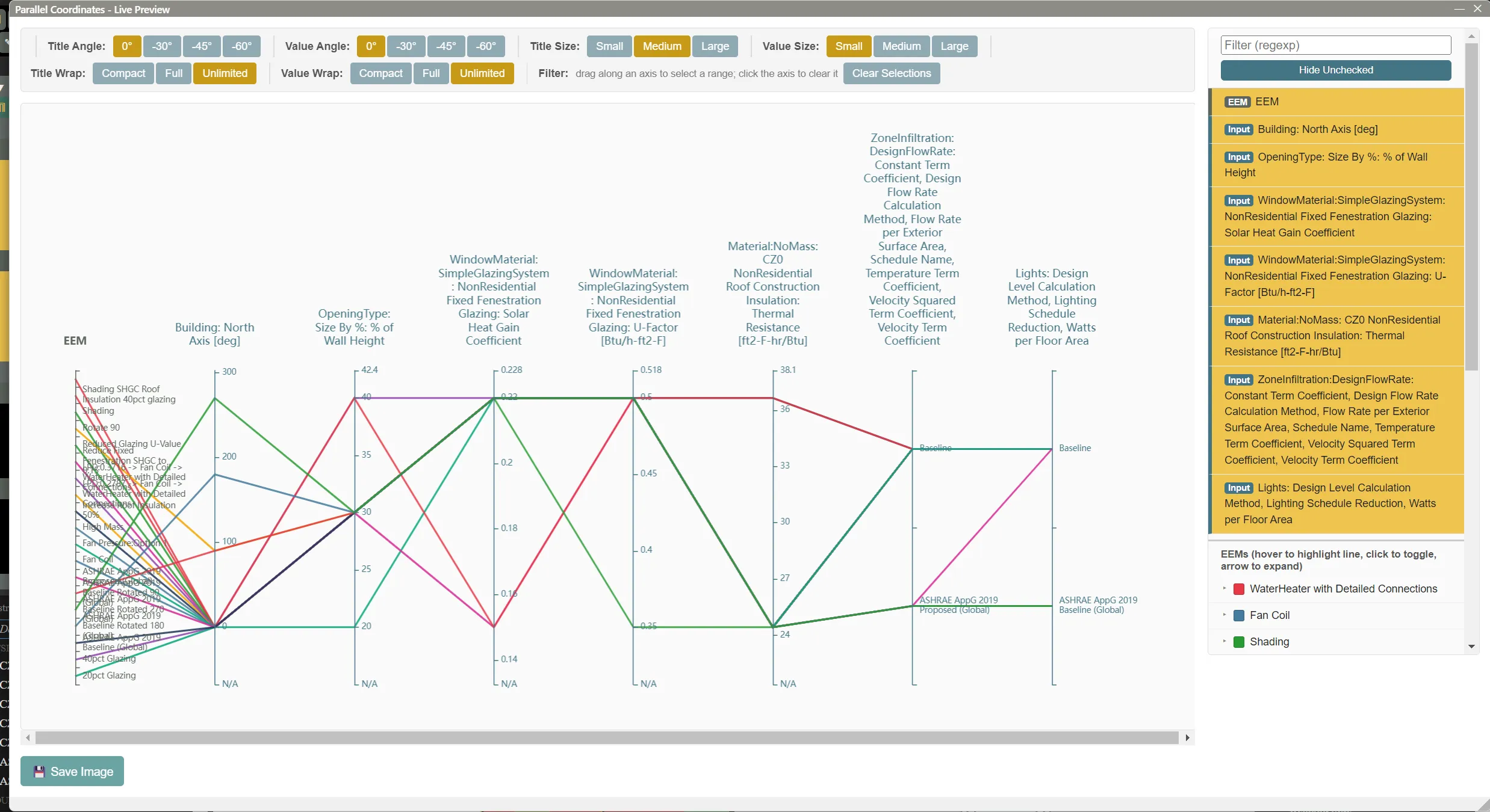
View Parallel Coordinates Plot (Live Preview) draws the inputs of the current model, before any simulation. Check EEMs in the list to plot only those; with none checked, every eligible EEM is plotted. Save Image saves the chart as a PNG.
8.3 The Parallel Coordinates tab
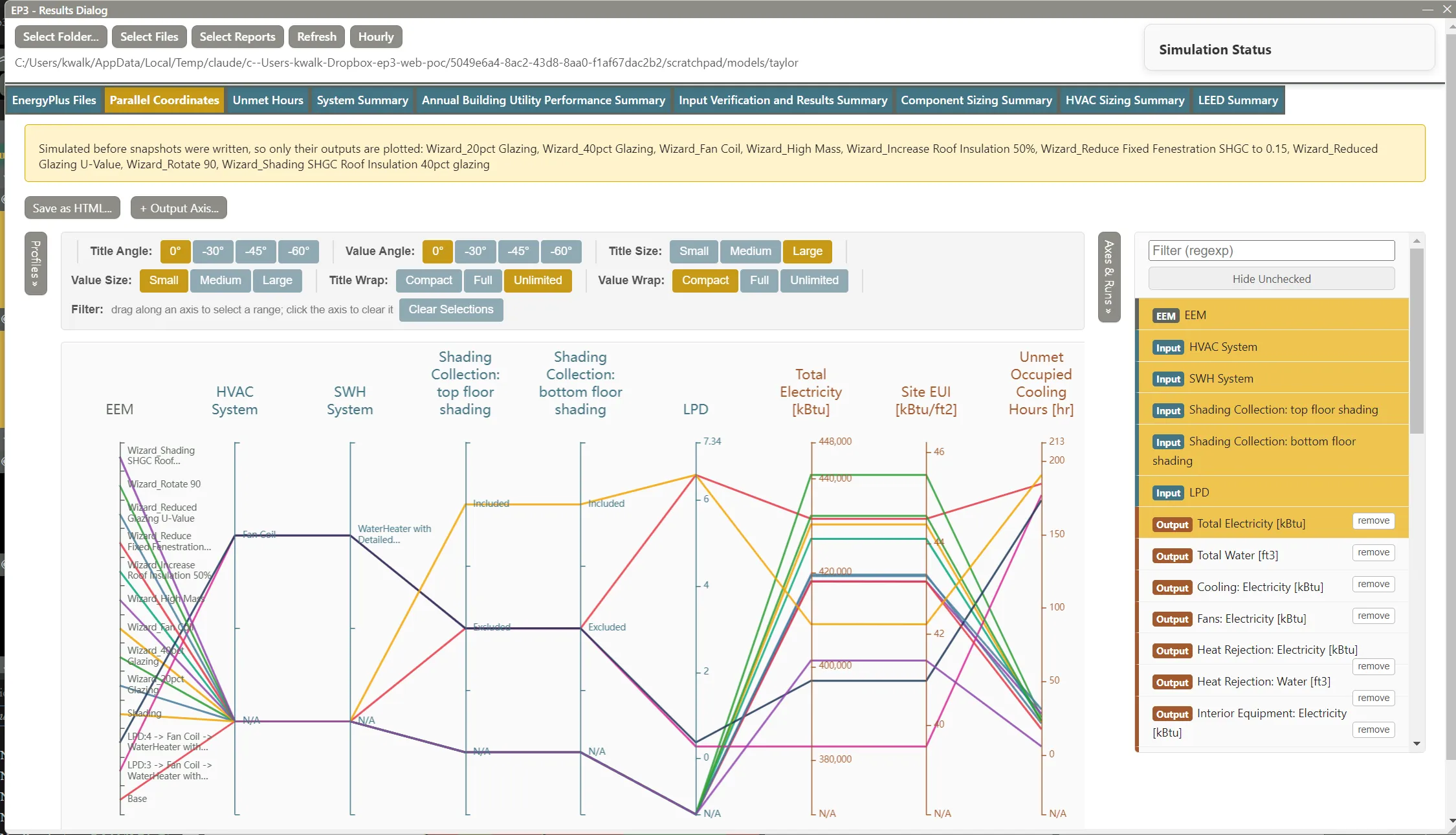
After a simulation, View Results opens the results viewer, whose Parallel Coordinates tab plots every loaded run. Each run’s inputs come from a snapshot of the EEMs saved with the run, so editing the model later does not change how a finished run is plotted.
- « Axes & Runs opens a drawer with every axis and every run. Click an axis to show or hide it, drag it to reorder, filter the list, or Hide Unchecked. Hover a run to highlight its line, and click it to hide or show it. The shown axes and their order are saved with the model.
- The tab fills the Results dialog; resize the dialog to resize the chart.
- An input axis on which every plotted run has the same value is left out, since it tells nothing about the difference between the runs. With a single run all axes show.
- A banner above the chart lists anything that affects the comparison: runs excluded because a change fits no axis, runs simulated before snapshots were written (plotted with outputs only), results files that may no longer match their snapshot, names that mean different things in different runs, Global values that differ between runs, and objects deleted since the runs.
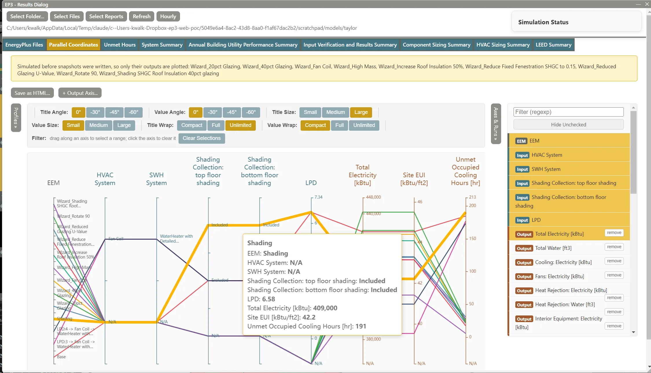
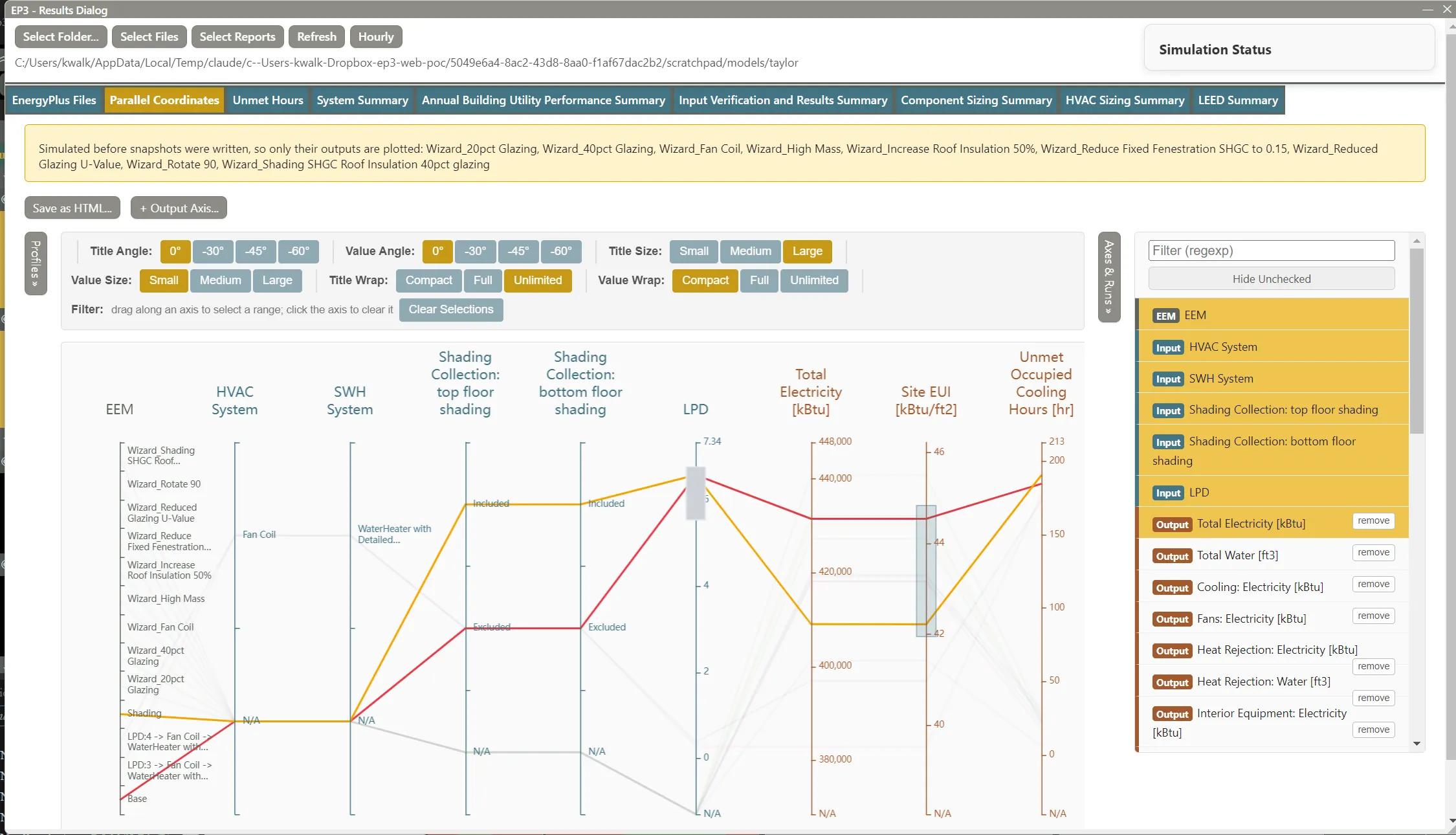
Reading and filtering the lines. These work in the Results tab, the Live Preview, and a saved HTML file (§8.5). Each shown axis has a fixed width, and the chart scrolls sideways when the axes do not fit.
- Hovering over a line thickens it and shows a card with the run’s name and its value on every shown axis.
- Dragging along an axis selects a range; on a category or bucket axis, the selection takes the bands it covers. Runs outside the selection fade. Selections on several axes combine: a run stays at full strength only inside all of them. Drag a selection to move it, and click the axis outside it to remove it. Clear Selections removes all of them, as does changing a control or showing or hiding an axis or a run.
8.4 Output axes and profiles
The default outputs are each fuel’s total and each end use by fuel that is non-zero in some run (Annual Building Utility Performance Summary, End Uses), Site EUI and Source EUI, Total Energy Cost when a tariff reported it (Utility Costs), and Unmet Occupied Heating Hours and Unmet Occupied Cooling Hours. To change them:
- + Output Axis… adds a Results table value (Report, For, Table, Row, Column) or a Time series total / average / min / max: a variable summed, averaged, or taken at its minimum or maximum over the run period or an MM/DD range within it. Design days are never counted.
- In any report table of the results viewer, hovering a number shows ⊕, which adds it as an axis; ⊖ removes an axis it already is.
- Each output axis in the drawer has remove, and a time-series axis edit for its aggregation and dates. A removed default stays off.
Profiles », the drawer at the left, holds output profiles: saved sets of output axes to apply to any model. Click a profile to apply it; EP3 ships Default Outputs. Save Current as Profile… saves the current outputs with a name and an optional note, and adds the chosen folder under Profile Folders. A profile holds outputs only; which inputs are shown stays with the model.
8.5 Save as HTML
Save as HTML… asks for a title and writes the chart, with its current axes and order, to one self-contained HTML file that opens in any browser without EP3 or the model.
Atlas can create EEMs, including branching EEMs, and read and arrange the parallel coordinates plot (The EP3 AI Assistant). The ASHRAE 90.1 PRM generator creates Proposed and Baseline EEMs (a Proposed and a Budget in the Energy Cost Budget Method, §9), and deleting them removes what the generator made for them (ASHRAE 90.1 Performance Rating Method).
9. Disaggregating an EEM
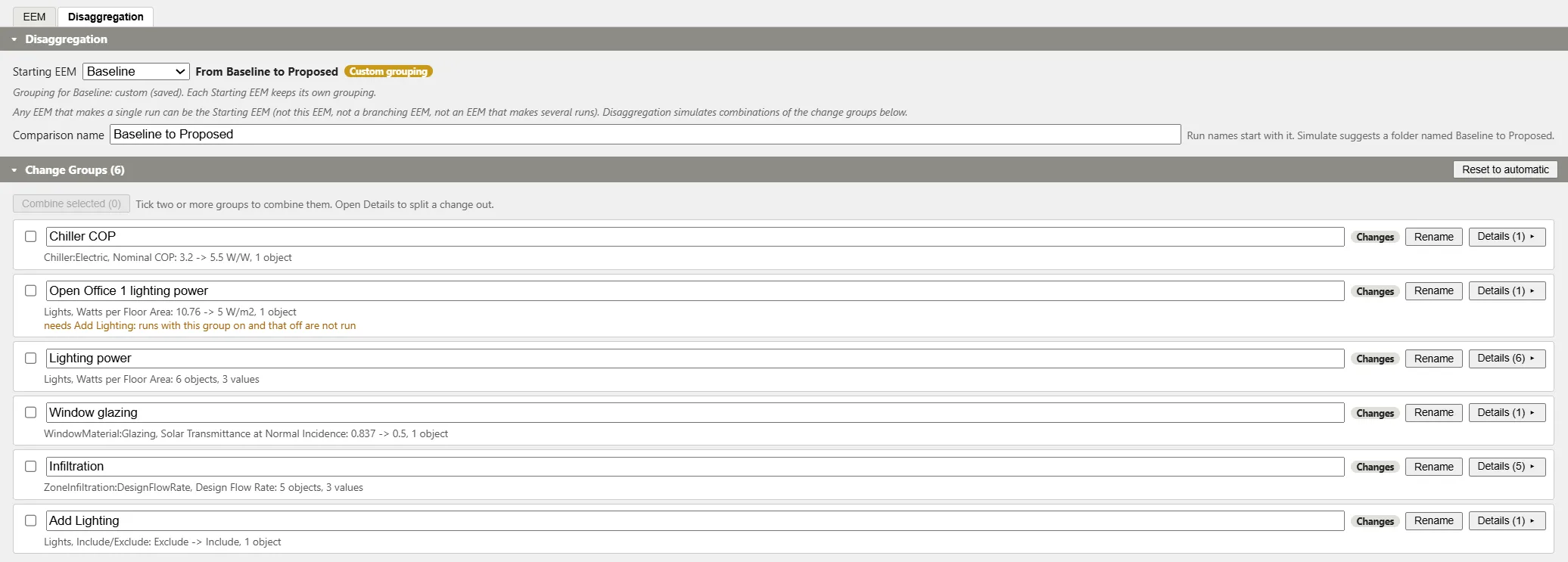
Two EEMs differ by a number of changes, such as a higher chiller COP, lower lighting power, and tighter infiltration. The results show the total difference, and disaggregation shows what each change contributes to it, with the interactions between changes included. EP3 splits the difference between the two EEMs into change groups, simulates combinations of those groups as separate runs, and the results viewer turns the runs into a share for each group (Viewing and Interpreting Results).
The two ends are the Starting EEM and This EEM. This EEM is the EEM whose page holds the disaggregation, and the Starting EEM is the EEM it is compared with. Either can be built on the other, so the names make no assumption about which one is the baseline. The examples use two EEMs named Baseline and Proposed on a five-zone office. Proposed builds on an EEM named Add Lighting, which builds on Baseline.
9.1 Opening the Disaggregation tab
An EEM’s page has two tabs, EEM and Disaggregation. Global, HVAC System, and SWH System have no Disaggregation tab. The tab has four sections:
- Disaggregation: the Starting EEM and the comparison name (§9.2).
- Change Groups: the changes between the two EEMs (§9.3).
- Run Set: which combinations to simulate (§9.4).
- Simulation Runs: the runs, with Simulate and Export epJSON (§9.5).
9.2 Choosing the Starting EEM
Starting EEM lists every EEM that makes a single run. This EEM, branching EEMs (including HVAC System and SWH System) and EEMs that make several runs because they include several iterations (§6.3) are not listed. The EEMs in This EEM’s chain come first, nearest first, then Global, then the other EEMs by name. A new disaggregation starts from the nearest EEM in the chain that qualifies, or from Global when none does.
The changes are the differences between the two models, found in both directions. This works the same whether one EEM builds on the other, both build on the same parent, or they are unrelated. A value stored in one EEM that matches what the other EEM resolves to anyway is not a change.
Comparison name names this comparison. It starts as <Starting EEM> to <This EEM>, such as Baseline to Proposed, and is used in run names, in a folder name, and in the results viewer (§9.5). Clearing it restores the default.
9.3 Change groups
Change Groups lists the pieces of the difference that EP3 switches on and off. Each group shows what it changes: the object type and field, the old and new values in the display units, and the number of objects. EP3 forms the groups as follows:
- HVAC System and SWH System are one group each when the two EEMs go through different system alternatives (§5.3), so a system switches as one piece and not object by object.
- The weather file is one group when the two EEMs simulate with different files. A run uses This EEM’s weather file only when this group is on.
- Every other change is split by object type and field, the way the parallel coordinates plot splits it (§8.1): a field given the same new value on every object is one group, and a field given different values is one group per object. Switching an object on or off is one group per object. Window sizes, a window’s OpeningType, shading properties, and the default constructions are one group each.
- A branching EEM that This EEM includes with several iterations is one group with a level for each iteration.
A group that depends on another reads needs <group>. A Lights object that the Starting EEM leaves out and This EEM brings in is an example: the object’s power change has an effect only where the object exists. A run with the dependent group on and the other off is not run, and is listed greyed with the reason (§9.5).
The grouping can be changed. Details opens a group’s changes.
- Split out takes a change out of its group into a group of its own.
- Ticking two or more groups and clicking Combine selected makes them one group, and all its changes switch together.
- Rename names a group. The name appears in the run list and in the results.
- Reset to automatic returns every group to the automatic grouping, after a confirmation.
The HVAC System, SWH System, and weather file groups, and groups with levels, cannot be split. The first three can be combined with other groups.
A badge reads Automatic grouping or Custom grouping. EP3 keeps a custom grouping and its run choices for each Starting EEM, so switching the Starting EEM brings back that Starting EEM’s grouping, or an automatic one. When the model changes after a custom grouping was made, changes that no longer exist are dropped, and new changes go into groups marked new, with a notice. Keep as is accepts them and Reset to automatic regroups. Nothing is regrouped without a request.
The number of runs grows with the number of groups: n groups give up to 2^n combinations. Combine changes that belong together, such as every lighting power value, before running every combination.
9.4 Run sets
Run Set chooses which combinations of groups are simulated:
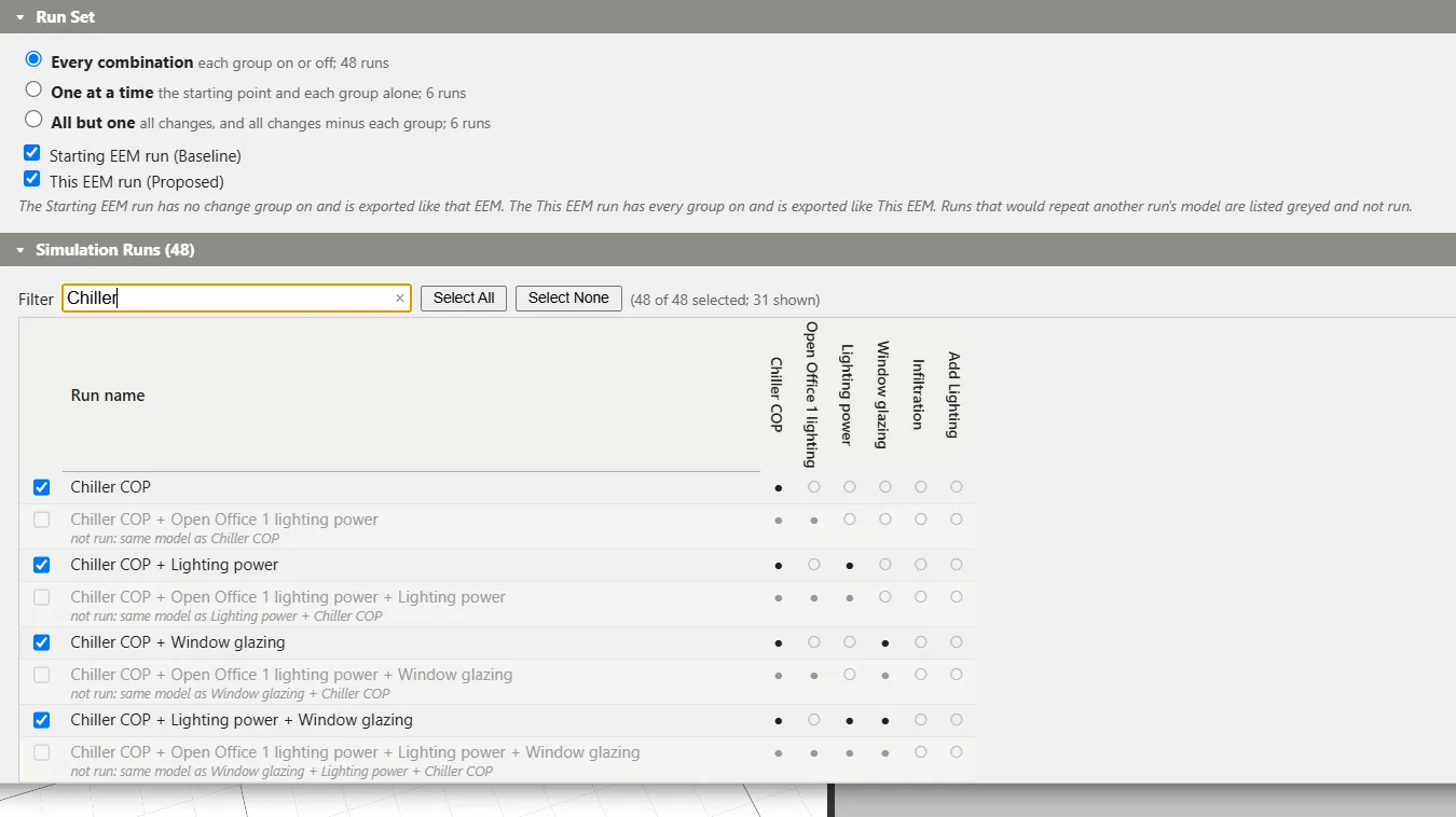
- Every combination: each group on or off, up to 2^n runs. This set gives the full result, with every interaction accounted for.
- One at a time: the starting point and each group on alone, n + 1 runs.
- All but one: all changes, and all changes except one group in turn, n + 1 runs.
Two checkboxes apply to every set: Starting EEM run (no group on, exported exactly like the Starting EEM) and This EEM run (every group on, exported exactly like This EEM). They give the two end values. A combination that would repeat another run’s model is not simulated twice: in the example, six groups give 64 combinations, of which 48 are simulated.
9.5 Choosing and running the simulations
Simulation Runs lists the runs of the chosen set. Each row has a checkbox, a name made of the groups that are on, and a dot for each group, filled where the group is on. A row that repeats another run’s model is greyed, with a line such as not run: same model as Chiller COP, and cannot be ticked.
The Filter box narrows the list by run name. The text is used as a regular expression when it is a valid one, and as plain text otherwise. Select All and Select None act on the rows shown, so a filter selects a subset, such as every run with the chiller change on. The heading counts the selection, for example (48 of 48 selected; 31 shown).
Simulate (N selected) runs the ticked runs as the Simulate / Export dialog does (Running Simulations): EP3 checks the weather file, asks for a folder, asks before overwriting files, and shows each run’s progress, with Cancel and View Results. Export epJSON writes the files without simulating.
- More than 8 runs asks for confirmation, and more than 64 asks for a tick on I understand this runs N simulations.
- The limit is 4096 combinations. Above it Simulate is disabled; combine groups, or choose One at a time or All but one.
- The runs go into a subfolder of the chosen folder, named after the comparison, such as
Baseline to Proposed. - A run is named
<comparison>: <groups on>in the results viewer, such asBaseline to Proposed: Chiller COP + Window glazing, and its files are named<comparison>_<groups on>. When that is too long for a file name, the file name uses a short code in place of the groups. The Starting EEM and This EEM runs keep their ordinary run names (Running Simulations).
Disaggregation adds no EEMs and no objects to the model. Each run is exported from a temporary copy in which every change is switched as its group requires.
9.6 Where the results appear
View Results opens the Disaggregation tab of the results viewer, which shows each group’s share of the difference (Viewing and Interpreting Results). The runs also appear in the Parallel Coordinates tab, with one axis for each group (§8.3). Atlas reads the same change groups when asked what an EEM changes (The EP3 AI Assistant).
10. Where to Look Next
- The Model Wizard — how imported systems become HVAC and SWH EEMs.
- The HVAC Outliner and Creating HVAC Systems — power buttons in the HVAC Outliner and building systems inside an EEM.
- Zone-Level HVAC Equipment and Zone Sizing — zone equipment assignments by EEM.
- Running Simulations — the Simulate / Export dialog.
- Viewing and Interpreting Results — the rest of the results viewer, and the Disaggregation tab (§9).
This handbook is also built into EP3 (Help), where its EnergyPlus links open the EnergyPlus Reference. Technical specifications · Book a demo