ASHRAE 90.1 Performance Rating Method
1. Overview
The ASHRAE 90.1 performance path button on the top toolbar (the balance scale) runs EP3’s ASHRAE 90.1 Appendix G (Performance Rating Method) generator. From an EEM you choose, it builds two EEMs, a Proposed and a Baseline, applies the Appendix G modeling rules to each, and simulates them. When the building is not oriented by its site, it also builds and simulates the Baseline turned 90, 180, and 270 degrees, together. Afterwards, the PRM Report button (the balance scale with a page behind it) shows the generator’s messages, the performance cost index, and compliance documentation in the format of the LEED Minimum Energy Performance Calculator.
You choose the edition: ASHRAE AppG 2022 (LEED v5 EAp2 Option 2), ASHRAE AppG 2019 (LEED v5 Option 1) or ASHRAE AppG 2016 (LEED v4.1). 90.1-2010 is not offered. A 2022 or 2016 run follows the same steps; §3.1 lists what differs from 2019.
The work runs in this order:
- Classify the building: Building Segments, the zones in each, and each space’s ASHRAE space types (§2).
- Run the generator: validation, then the Proposed and Baseline stages and their simulations (§3).
- Review what it built (§4, §5) and work through its action items (§6).
- Read the performance comparison and complete the documentation (§7).
The generator does not cover everything Appendix G requires; §8 lists what the modeler enters or checks by hand.
The same button also runs the Energy Cost Budget Method (ECB): Section 11 of ASHRAE 90.1-2016 and 2019, Section 12 of 90.1-2022. Both paths are valid; you pick one for a project. The ECB builds a Proposed and a Budget instead of a Proposed and a Baseline, and the Budget is the Proposed changed as Table 11.5.1 says. §9 covers it. The launcher, the validation, the unmet hours gate, the messages and the documentation work as described in §2 to §7 for both.
2. Preparing the model
2.1 Climate zone, weather file, and saving
The generator needs:
- the Climate Zone in General Model Settings, which selects the Baseline constructions, the HVAC system column, economizers, and the building performance factor. Choosing a weather file sets it from the file’s
.statwhen that can be read; you can pick another zone, or return to Automatic (Weather, Climate, and Design Conditions); - a weather file on disk for the EEM you generate from, with the site’s
.ddyfile in the same folder, from which the Baseline takes its design days and condenser water design wet-bulb (§5.1); - the desktop app, since it runs EnergyPlus;
- a model in EnergyPlus 23.2 or later, in every edition. EnergyPlus 23.1 does not report which fans are supply, return, or relief fans, and the Baseline’s fan power allowance is shared among them in the Proposed’s proportions (§5.8), so the generator does not run for a 23.1 model. Change the model’s version in File > EnergyPlus Version…, with that version installed (Settings > EnergyPlus Installations; EnergyPlus Versions);
- a saved model: the simulations go in an
ASHRAE_901_PRMfolder beside the.ep3file.
2.2 Building Segments
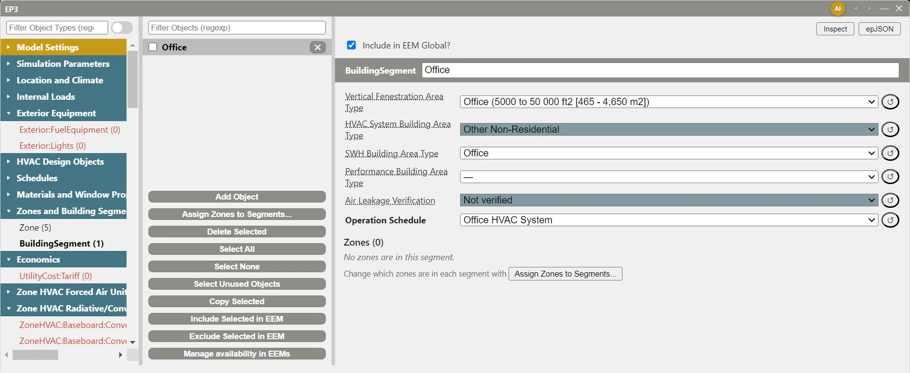
A Building Segment groups zones that share an Appendix G building area type. It is an EP3 object (not exported to EnergyPlus), listed in the main object dialog under Zones and Building Segments > BuildingSegment. Create one with Add Object. Most buildings need one segment; a mixed-use building has one per use.
| Field | What the generator does with it |
|---|---|
| Vertical Fenestration Area Type | Baseline window-to-wall ratio, Table G3.1.1-1 (§5.2). Default Other. |
| HVAC System Building Area Type | Baseline HVAC system type, Table G3.1.1-3 (§5.6): Other Non-Residential (default), Residential, Public Assembly, Retail, Hospital, or Heated Only Storage. |
| SWH Building Area Type | Baseline service water heater, Table G3.1.1-2 (§5.5). Default All others. |
| Performance Building Area Type | Building performance factor, Table 4.2.1.1 (§7.3). Blank: inferred from the three area types above. |
| Air Leakage Verification | Proposed infiltration, Table G3.1-5(b) (§4.1): Not verified (default), Verified (Section 5.9.1.2), or Whole-building test. |
| Measured Air Leakage at 75 Pa | Shown for Whole-building test: the tested leakage per unit of envelope area. |
| Operation Schedule | The segment’s on/off operating schedule. It sets the infiltration schedule, the fan schedule of zones without their own, and the operating hours used in system selection. Its Schedule Type Limits must be Discrete with a range of 0 to 1. |
2.3 Assigning zones to segments
A zone belongs to the segment in its Building Segment field, on the Zone or, more often, on its ZoneType’s Zone Properties tab (Internal Loads, Space Types, and Zone Types). The zone’s value wins over the ZoneType’s.
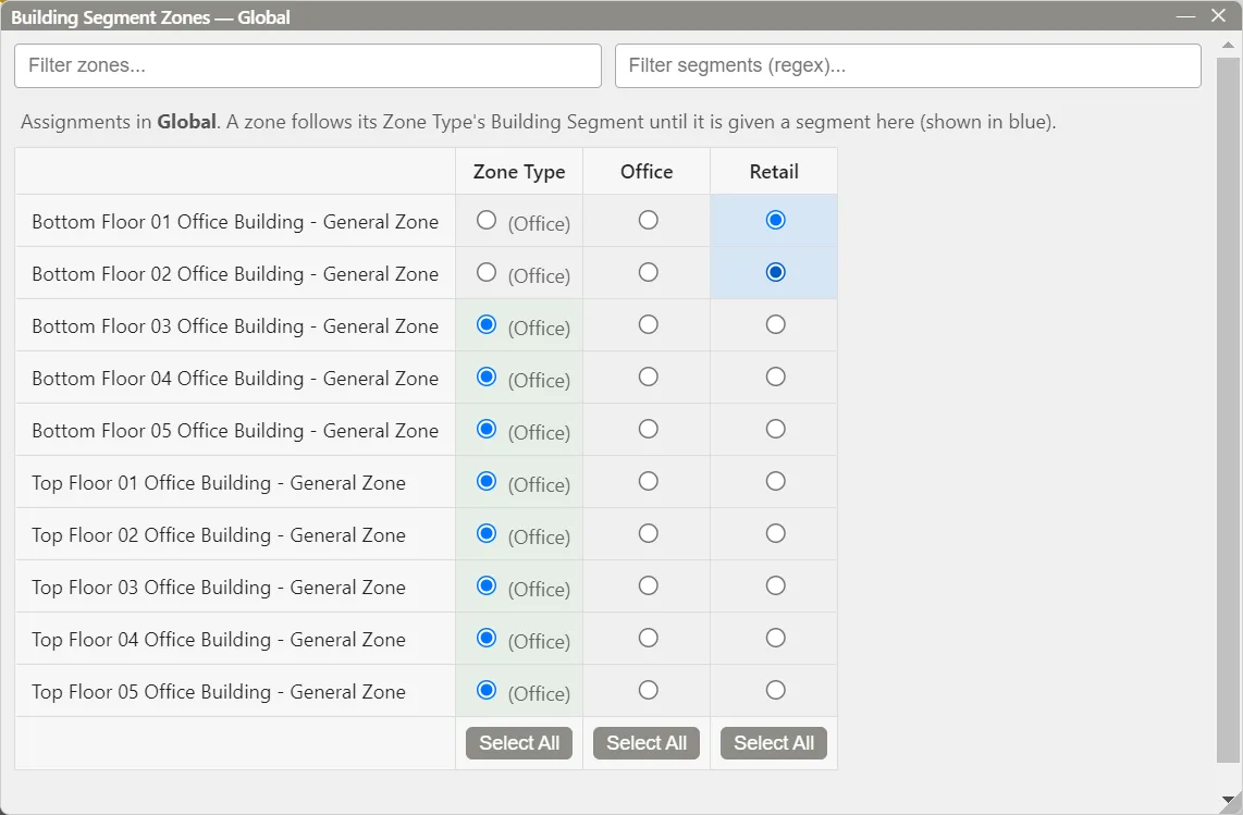
Assign Zones to Segments… (Column 2, with BuildingSegment selected) opens the Building Segment Zones dialog: one row per zone and one radio column per segment, plus a Zone Type column for a zone that follows its ZoneType. A zone given its own segment is shown in blue. The filter boxes narrow the zones and segments, and the buttons under each column assign every visible zone at once. Assignments are made in the active EEM; in an EEM other than Global, ↺ drops that EEM’s change. The selected segment’s Column 3 lists its zones.
A zone made only of unregulated spaces (Space Function Plenum, Attic, Crawl Space, or Interstitial Space) needs no segment.
2.4 Space classifications
Each regulated space needs an Envelope Space Type, a Lighting Space Type, and a Space Function, set on its SpaceType’s ASHRAE Space Types tab (with a column per space for exceptions) or on the space itself (Internal Loads, Space Types, and Zone Types). The Library’s templates have them filled in.
| Field | Used for |
|---|---|
| Envelope Space Type | Nonresidential, Residential, or Semiheated (the columns of Tables G3.4-1 to G3.4-8), or Unconditioned. A space with none is treated as Nonresidential; a zone of only Unconditioned spaces gets no Baseline system. |
| Lighting Space Type | The Table G3.7 space type (“Primary: Secondary”, such as Office: Open plan): Baseline lighting power, the Table 9.6.1 minimums, computer rooms, laboratories, and the heated-only exception. |
| Ventilation Space Type | The Standard 62.1 (or 170) category. Optional: validation does not require it, and no generator stage reads it. |
| Space Function | Other for most spaces. Laboratory and Kitchen trigger their own rules; Plenum, Attic, Crawl Space, and Interstitial Space make the space unregulated. |
| Space Conditioning Category Change? | For a renovation: Yes when the space’s conditioning category changes, which gives it the full Baseline envelope. |
| Is Vestibule? | On the space only: an entrance vestibule, which can take the heated-only system (§5.6). |
The SpaceType also has HVAC Space Type, kept from the library; the generator reads the HVAC area type from the Building Segment.
2.5 Other inputs the generator reads
| Input | Where | Effect |
|---|---|---|
| Orientation Dictated by Site? | The Building (double-click the Building row in the Building Geometry Outliner), Global only | Yes skips the three rotated Baselines (Table G3.1, Section 5(a)). |
| Natural Gas Available on Site? | The Building, Global only | No makes the Baseline water heaters and boilers burn propane. |
| Construction Is All New? | Each construction (Constructions and Materials) | No marks an existing construction kept in a renovation: its surfaces keep their construction and windows in the Baseline. |
| Roof Aged Test Data? | Material and Material:NoMass |
Yes keeps a roof’s modeled solar reflectance in the Proposed (§4.1). |
| PRM End-Use Subcategory, Receptacle Controlled Fraction (RC) | ElectricEquipment |
The receptacle power credit (§4.3) and the regulated/unregulated split (§7.3). |
| Lighting Purpose, Lighting Schedule Reduction | Lights |
General, Task, and Decorative lighting gets the Baseline lighting power; Retail Display is capped; Unregulated stays as designed. The schedule reduction models occupancy controls on a Schedule:Compact. |
| Building Exterior Type (Table G3.6) and its quantity fields | Exterior:Lights |
The Baseline exterior lighting allowance (§5.3). |
Elevator |
Main object dialog, Internal Loads | The Baseline elevator (§5.4). |
| Thermostats | ZoneType or Zone | A zone with no thermostat gets no Baseline system. |
DesignSpecification:OutdoorAir on each Sizing:Zone |
ZoneType’s Sizing:Zone |
The Baseline’s ventilation and demand control ventilation. |
Fan:ZoneExhaust maximum flow in laboratory zones |
Zone equipment | The laboratory exhaust total in Section G3.1.1(d). |
| Utility tariffs | Utility Costs | The energy cost of each fuel that has one. |
3. Running the generator
3.1 The launcher
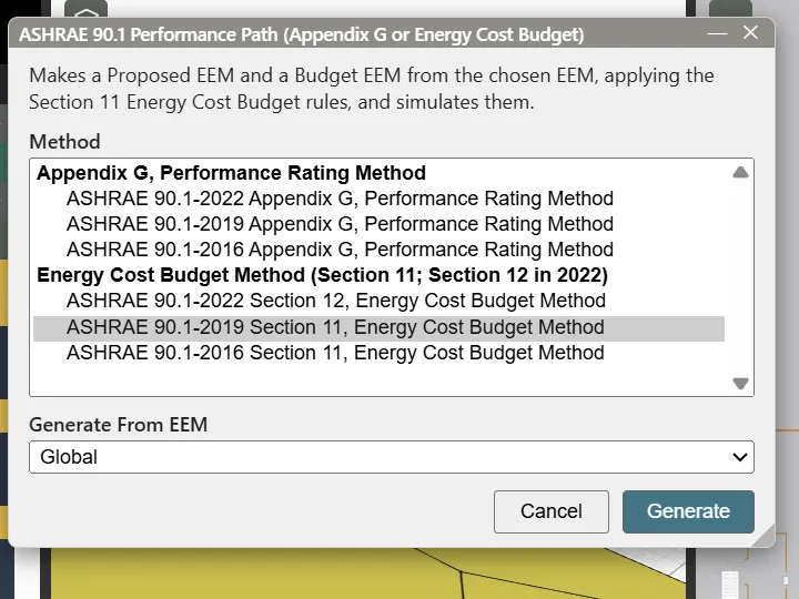
The balance-scale button opens ASHRAE 90.1 Performance Path (Appendix G or Energy Cost Budget):
- Method — the list has two groups. Appendix G, Performance Rating Method offers ASHRAE 90.1-2022 Appendix G, 2019 and 2016. Energy Cost Budget Method (Section 11; Section 12 in 2022) offers ASHRAE 90.1-2022 Section 12, 2019 Section 11 and 2016 Section 11 (§9). The edition sets the rules and tables, names the EEMs, and sets the section citations in the messages and the documentation (90.1-2022 renumbers most of Appendix G: Section G3.1.2.9 is G3.2.2.8 there, for example). Choose the method your project’s compliance path uses; the rest of this section and §4 to §8 describe Appendix G.
- Generate From EEM — the EEM that holds the design. Global is the usual choice. EEMs the generator made, and EEMs built on them, are not offered.
The dialog says why Generate is unavailable: outside the desktop app, when the model is in EnergyPlus 23.1 (§2.1), or before the model is saved.
What a 2016 run does differently. The steps are the same. These rules change (90.1-2016 Appendix G):
- Infiltration is 0.4 cfm/ft² at 75 Pa in the Proposed and the Baseline. A segment set to Verified (Section 5.9.1.2) is run as not verified, with a warning; a Whole-building test still uses the measured rate.
- No receptacle power credit (§4.3), and no 0.60 W/ft² floor for dwelling units: guest rooms and dormitories still reach their Table 9.6.1 allowance, and dwelling units get an action item about receptacle-connected lighting.
- Baseline boilers burn natural gas when anything in the Proposed does; otherwise the Proposed’s own combustion fuel, and natural gas when it burns none (propane where gas is not available on site).
- Cooling efficiencies of packaged equipment come from the SEER, EER, and HSPF forms of Table G3.5.1 through the G3.1.2.1 conversion equations, and System 4 heat pumps take the 17°F heating COP of Table G3.5.2.
- Baseline water heaters follow the 2016 Table 7.8 (energy factor for small heaters; gas heaters over 75,000 Btu/h at 80% thermal efficiency).
- Fan power for Systems 12 and 13 is the 0.00094 bhp/cfm of Table G3.1.2.9, with an informational note.
- Building performance factors come from the 2016 Table 4.2.1.1, with no on-site renewable cap. The documentation cites the 2016 sections. The performance index is the energy cost index; the LEED v4.1 documentation is not built yet.
What a 2022 run does differently. The steps are the same, with two more stages. These rules change (90.1-2022 Appendix G):
- Baseline system selection (Section G3.2.1.1). Zones are grouped by building area type. Residential zones always get their own system, however small. The predominant nonresidential type takes in any other nonresidential type under 20,000 ft² (1,858 m²); a nonresidential type over 20,000 ft² gets its own system. Hospitals have their own rows in Table G3.1.1-3. Corridors and other zones that mainly serve residential spaces on residential floors (residential associated zones) get System 3 or 4. The “differs significantly” exception (Section G3.2.1.2(a)) applies only to Systems 5 to 8, at 12 Btu/h·ft² (37.9 W/m²), and compares occupied hours (more than 40 hours a week higher). A warning lists the zones whose system differs from what the 2019 rules would choose.
- Semiheated spaces (Table G3.1 item 5(b), Table G3.4-9). After the Baseline sizing run, a space that is semiheated in the Proposed gets the conditioned envelope in the Baseline when the Baseline system serving it has at least 5 Btu/h·ft² (15.8 W/m²) of sensible cooling output, or heating output at or above the Table G3.4-9 value for the climate zone (5 to 25 Btu/h·ft²), or when it is indirectly conditioned. Its constructions and windows are then set again and the Baseline is sized once more. An action item lists each space that changed and why; the Proposed and your model keep Semiheated.
- Infiltration. A segment set to Verified (Section 5.9.1.2) gets 0.45 cfm/ft² at 75 Pa in the Proposed (0.6 in 2019); the Baseline stays at 1.0.
- Walls. Baseline above-grade walls get a solar reflectance of 0.25 and a thermal emittance of 0.90 (Table G3.1 item 5(j)).
- Lighting comes from Tables G3.7-1 and G3.7-2, which add space types (they appear in the Lighting Space Type list); an earlier edition’s run maps them to its nearest row and says so. Exterior lighting surfaces that left Table G3.6 are lit as in the Proposed.
- Chillers use the Normative Appendix J performance curves of Table J-2, chosen by chiller type and size, and the Table G3.5.3 efficiencies to four decimals. The chiller count reads the coincident peak cooling load of the systems on chilled water. For a Proposed chiller with no part-load data, an action item names the Table J-1 curve sets that apply.
- Pumps. Hot water and chilled water pumps run only when their loop has a load. The exception is the constant-speed primary chilled water pump of a primary/secondary plant: it stays on whenever the chillers are available, because EnergyPlus otherwise leaves the cooling coils without water when cooling starts. The secondary pump still runs only on a load, and the run log says so.
- Energy recovery gains exception 8: a system serving laboratory zones whose exhaust totals more than 15,000 cfm (7.08 m³/s) gets none.
- Service water heating. A gas water heater of 1,000,000 Btu/h (293 kW) or more gets an action item naming Section 7.5.3.
- Renewable energy runs. Together with the Proposed’s own run, the Proposed is also simulated with its on-site renewable systems off and with them scaled to the capacity Section 10.5.1.1 requires, or with a reference photovoltaic system when it has none (§7.3). When the unmet-hours check later changes the Proposed’s schedules (§5.10), these runs are made again at the end.
- Performance. The target includes the prescriptive renewable energy credit (PRE) and the 2022 Table 4.2.1.1 building performance factors (§7.3).
In every edition the Baseline’s sizing runs size each plant on the coincident peak of the systems it serves, and Baseline chillers get minimum part-load and unloading ratios of 0.25.
3.2 Validation
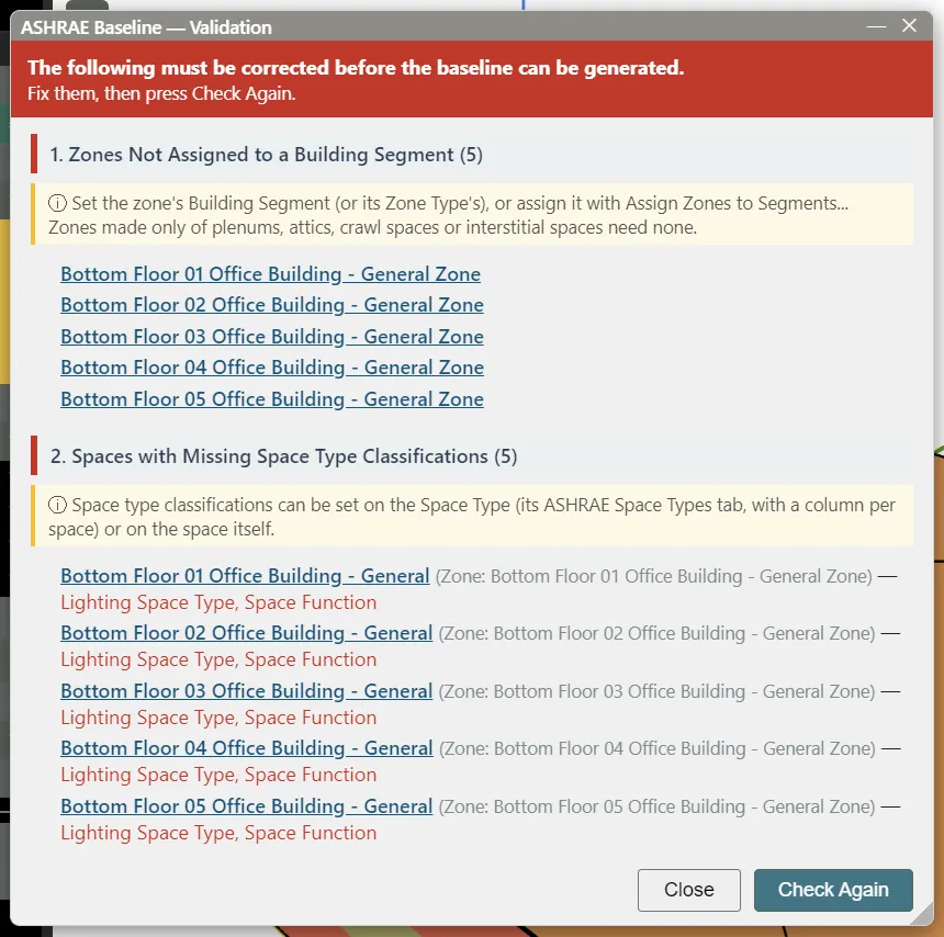
Generate first checks the model. When something must be fixed, ASHRAE Baseline — Validation lists it in numbered sections:
- No Climate Zone.
- Weather File Not Available — none assigned, or the file is not on disk.
- EnergyPlus Version Too Old — the model is in EnergyPlus 23.1; the generator needs 23.2 or later (§2.1).
- Zones Not Assigned to a Building Segment — zones with at least one regulated space; set each zone’s Building Segment or use Assign Zones to Segments… (§2.3).
- Building Segments with Missing Required Fields.
- Building Segments with an Invalid Operation Schedule Type — the schedule is not on/off.
- Spaces with Missing Space Type Classifications — a regulated space without an Envelope Space Type, a Lighting Space Type, or a Space Function, with its zone and the fields missing.
- Space Conditioning Category Change — a space marked as changing category whose surfaces have a construction with Construction Is All New? No.
Each zone or segment name opens that object in the main object dialog, and each space name selects the space in the drawing. Fix the items and press Check Again.
PRM Baseline inputs. Once the model passes validation, and before anything is generated, PRM Baseline inputs (Budget inputs for an Energy Cost Budget run, §9.3) asks what the generator cannot read from the model, so the run can go on without you at the computer. It lists each air system of the design: every air loop, and every zone unit with a fan. For each:
-
Fan pressure-drop credits (Table 6.5.3.1-2): tick the devices the system has, with the share of the system’s airflow through each (100% unless you enter less), and the value a device’s credit needs:
- fixed credits: ducted return or exhaust, 0.5 in. w.c. (2.15 for a laboratory or vivarium system); return or exhaust airflow control, 0.5; MERV 9 to 12, 0.5; MERV 13 to 15, 0.9; coil runaround loop, 0.6 per airstream; sound attenuation, 0.15; fume-hood exhaust, 0.35;
- entered values: the pressure drop of exhaust treatment, gas-phase air cleaners, biosafety cabinets and evaporative coolers; the clean-filter drop of MERV 16 filters (counted twice); the enthalpy recovery ratio of energy recovery; the vertical duct length of laboratory exhaust in a high-rise building (0.25 in. w.c. per 100 ft beyond 75 ft).
Tick No pressure-drop credits for a system that has none. EP3 fills in what the model shows (energy recovery with its ratio, an evaporative cooler in series with a cooling coil) for you to check. The credits are not used where the Baseline gives the zones System 1, 2, 9 or 10, whose fan power is 0.3 W/cfm.
-
Exceptions, asked only where they can apply, each answered Yes or No:
- Section G3.1.2.6 Exception 1, gas-phase air cleaning to meet Standard 62.1 Section 6.1.2: asked once the gas-phase cleaner credit is ticked, in climate zones where the Baseline has economizers;
- Section G3.1.2.6 Exception 2, supermarket open refrigerated casework: for systems serving supermarket spaces that have no economizer;
- Section G3.1.2.10 Exception 2, toxic, flammable or corrosive fumes, paint or dust: for systems serving laboratories or zones with zone exhaust fans;
- Section G3.1.2.10 Exception 3, Type I commercial kitchen hoods: for systems serving kitchens;
- Section G3.1.2.10 Exception 6, largest exhaust source under 75% of the design outdoor air: for systems supplying 70% outdoor air or more;
- Section G3.1.2.10 Exception 7, dehumidification with energy recovery in series with the cooling coil: for systems serving zones with humidity control.
The energy recovery questions are asked only for systems without energy recovery in the design, as the exceptions require. In 90.1-2022 these sections are G3.2.2.5 and G3.2.2.9.
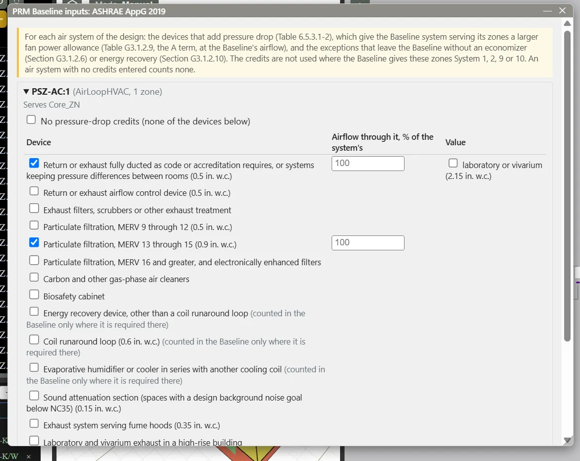
Save and continue saves every answer together with the model; Continue without saving goes on with the answers saved before. The answers are kept for later runs and shown again under Documentation Inputs (§7.5). Nothing here is needed to run the generator: a system left with no credits counts none, and the Messages say so.
3.3 Unmet hours before generation
Appendix G allows 300 occupied hours with setpoints not met in the Proposed and in the Baseline (Section G3.1.2.3; Section G3.2.2.3 in 90.1-2022). Before any step, the generator checks the starting EEM’s latest annual run. With no run, or a model changed since its run, it simulates the EEM first (the run is kept and reused next time). Within 300 hours, generation goes ahead.
Over 300 hours, the progress dialog shows the hours and asks:
- Show the unmet hours opens that run in the Results dialog’s Unmet Hours tab, which explains the hours as warm-up, capacity, or control (Viewing and Interpreting Results). Ask Atlas for help sends the question to the assistant.
- Fix it first stops the run before anything is made. Fix the design, then press Generate again.
- Continue anyway asks you to confirm. It means you take on resolving the unmet hours in both models: the generator makes no schedule changes and no sizing-factor changes, each EEM gets an action item saying so (the Proposed’s with its hours), and the documentation states it.
The Proposed is checked again after its own run, with the same two answers, because it can differ from the starting EEM. Continue anyway at the first question carries over.
An Energy Cost Budget run asks the same question, citing Section 11.5.2(i) (Section 12.5.2(i) in 2022), which allows 300 hours in the Proposed and in the Budget. Continue anyway then means EP3 makes no warm-up schedule changes for the Budget (§9.7).
3.4 EEMs from an earlier run
When an earlier run made EEMs from the same EEM and vintage, ASHRAE Baseline — Existing EEMs offers, for each:
- Keep — reuse it as it is and skip its stages this run.
- Rename — keep it under a new name, no longer the generator’s; a new one is made.
- Delete — remove it (a Baseline’s rotated copies go with it) and the objects that were on only in it; a new one is made.
A Baseline is built on its Proposed, so making a new Proposed deletes a kept Baseline (choose Rename to keep a copy). An EEM whose run stopped part way cannot be kept. Proceed starts the run.
A re-run does not add copies. A new set of EEMs reuses the objects an earlier run left in the model (windows, constructions, systems, schedules) and sets their values in the new EEMs, so running the generator again leaves the model the size it was after the first run.
Deleting the EEMs yourself. The ✕ on a Proposed or Baseline in the EEM list deletes it like any EEM: a dialog counts the objects that are on only in it and lets you keep any of them (Energy Efficiency Measures (EEMs)). Everything the generator made for the EEM goes with it, such as its Baseline windows, systems, and warm-up schedules. Your own objects are turned off in that EEM, never deleted with it.
3.5 Progress
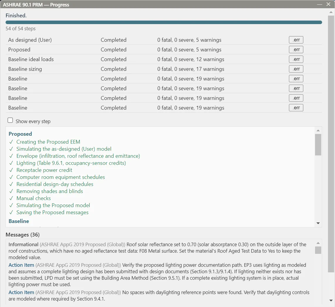
ASHRAE 90.1 PRM — Progress shows the current step, a progress bar with the count of steps finished, and the steps under Proposed and Baseline, each marked waiting, running, done, skipped (an EEM was kept), or stopped. Each EnergyPlus run is listed with its state and its fatal, severe, and warning counts, with an .err button, and a long step such as the warm-up trials shows how far it has got. The three rotated Baselines are simulated at the same time. Messages appear below as the stages log them.
Cancel stops after the current step and stops a running simulation. A failed simulation stops the run with an error naming the EEM to fix. When the run ends, View Results, View Messages, Documentation (after a completed run), and Close are offered.
The whole run is one undo step, also when it fails or is cancelled.
A run simulates several times. Each run’s files are in ASHRAE_901_PRM, named <model>_<EEM name>:
| Run | Prefix | Purpose |
|---|---|---|
| As designed | (User) |
The starting EEM as modeled, before any Proposed change; the run the unmet-hours check (§3.3) reads. The documentation reports it beside the Proposed. |
| Proposed | The Proposed model, annual. | |
| Baseline ideal loads | (Ideal Loads) |
Sizing only, every Baseline zone on an unlimited ZoneHVAC:IdealLoadsAirSystem. Its loads set the Baseline efficiencies and water heater sizes. |
| Baseline sizing | (Sizing) |
Sizing only, the Baseline systems. Its airflows and capacities set fan power, pumps, and the chiller plant. |
| Baseline | The Baseline, annual, repeated while unmet hours are fixed (§5.10). | |
| Warm-up trials | Short runs of a few air loops over the worst weeks, in a Trials folder, to choose a warm-up fix. |
|
| Baseline rotations | Each rotated Baseline, annual. |
Every annual PRM run covers a full calendar year. Running Simulations covers EnergyPlus runs and their error files, and Viewing and Interpreting Results covers reading them (open the ASHRAE_901_PRM folder with the Results dialog’s Select Folder…).
3.6 While the generator runs
The model is closed to edits from Generate until the run ends, fails, or is cancelled, so the models it builds and the model you see cannot drift apart. A refused change shows “The ASHRAE 90.1 PRM generator is running. The model can’t be changed until it finishes or is cancelled.” in the status line.
- Still works: selecting, orbiting, the tape measure, opening dialogs to read them, the Results dialog, and view-only toggles such as showing or hiding floors, grade, and drawings.
- Greyed out: the drawing and editing tools, the Outliner’s add and delete buttons, and the fields of every dialog except the viewers and the PRM dialogs. Undo and redo wait too.
- Atlas can read the model, answer, and show results, but its changes, measures, and simulation requests are refused until the run ends. Integrate and Approve on an open card wait; Reject and Decline still work.
3.7 The EEMs it makes
| EEM | Parent | Holds |
|---|---|---|
| ASHRAE AppG 2019 Proposed (start EEM) | The EEM you generated from | The Proposed changes (§4). |
| ASHRAE AppG 2019 Baseline (start EEM) | The Proposed | The Baseline changes (§5). |
| ASHRAE AppG 2019 Baseline Rotated 90 / 180 / 270 (start EEM) | The Baseline | Only the Building’s north axis, turned by that angle. |
A 2016 run names them “ASHRAE AppG 2016 …” the same way.
Because the Baseline inherits from the Proposed, the loads, schedules, and thermostats the Appendix G rules keep the same in both are entered once. The objects the Baseline adds, such as its windows, constructions, HVAC systems, and water heaters, are off in Global and on in the Baseline; the design’s objects they replace are turned off in the Baseline. Select the EEM in the toolbar’s EEM dropdown to see either model in the 3D view, the HVAC diagram, and the dialogs (Energy Efficiency Measures (EEMs)).
3.8 The starting model’s cooling check
Both methods simulate every conditioned space as heated and cooled (Table G3.1 items 1(b) and 10(d); Table 11.5.1 item 1(b) and 10(d), Table 12.5.1 in 2022). EP3 checks this right after the unmet hours check, under the progress step Checking the starting model’s unmet hours and cooling. It lists every zone of the starting EEM that has a thermostat and no cooling coil, on its own equipment or on its air loop, and a zone with no HVAC at all. Zones in a Building Segment whose HVAC System Building Area Type is Heated Only Storage are left out, and so are zones without a thermostat.
The check warns and never blocks: the run goes on, and the Proposed and the Baseline (the Budget in an ECB run) each get an action item naming the zones. EP3 adds no cooling to your model. The Baseline or Budget gives such a space its own cooling system, because the standard simulates it as cooled. Either add cooling to the starting model, or, for a heated-only storage room, stairwell, vestibule, electrical or mechanical room or restroom, set the Building Segment’s HVAC System Building Area Type to Heated Only Storage (the Appendix G exception to item 1(b)). The Documentation repeats the Proposed’s item under Performance Outputs.
4. What the Proposed changes
This section is about the Appendix G Proposed. The Energy Cost Budget Method’s Proposed is changed less: its lighting control credits are in §9.2, and the Budget inputs it asks for are in §9.3.
4.1 Envelope
Infiltration. Each Building Segment’s spaces get infiltration from its air leakage at 75 Pa (0.3 in. w.c.), converted as Section G3.1.1.4 does: ZoneInfiltration:DesignFlowRate with Design Flow Rate Calculation Method Flow/ExteriorArea, a flow per exterior surface area of 0.112 × the leakage, and only the wind term (Velocity Term Coefficient 0.224). Infiltration, Natural Ventilation and Airflow Networks explains the conversion.
| Air Leakage Verification | Proposed leakage at 75 Pa | Baseline |
|---|---|---|
| Not verified | 1.0 cfm/ft² | 1.0 cfm/ft² |
| Verified (Section 5.9.1.2) | 0.6 cfm/ft² | 1.0 cfm/ft² |
| Whole-building test | Measured Air Leakage at 75 Pa (1.0 cfm/ft² with a warning when blank) | 1.0 cfm/ft² |
A design infiltration object that alone serves its spaces, all in one segment, is kept and re-rated; every other infiltration object in a segment’s spaces (including ZoneInfiltration:EffectiveLeakageArea, ZoneInfiltration:FlowCoefficient, and the airflow network) is turned off, and each segment’s remaining spaces get one new infiltration object on a SpaceList. Infiltration serving only spaces outside every segment, such as plenums, is left alone. The schedule is a copy of the segment’s operation schedule with 1.0 where it is 0 (closed) and 0.5 where it is open; it needs a Schedule:Compact operation schedule.
Worked example: a verified envelope. For Verified (Section 5.9.1.2), 0.6 cfm/ft² at 75 Pa:
- IP: 0.112 × 0.6 = 0.0672 cfm/ft² of exterior surface.
- SI: 1 cfm/ft² = 0.3048 m ÷ 60 s = 0.00508 m³/(s·m²), so 0.0672 × 0.00508 = 0.000341 m³/(s·m²).
- A zone with 200 m² (2,153 ft²) of exterior surface at the 10 mph (4.47 m/s) reference wind: 0.000341 × 200 = 0.0683 m³/s, and 0.0672 × 2,153 = 144.7 cfm (0.0683 × 2,118.9 = 144.7 cfm).
The Baseline’s 1.0 cfm/ft² gives 0.112 cfm/ft² (0.000569 m³/(s·m²)), 241 cfm for the same zone.
Roofs. The outside layer of each exterior roof construction is given a solar reflectance of 0.70 (solar absorptance 0.30), unless its material’s Roof Aged Test Data? is Yes. The change is made on the material, so every construction with that outside layer changes in the Proposed.
Shades and blinds. WindowShadingControl, WindowMaterial:Shade, WindowMaterial:Blind, and WindowMaterial:Screen objects are turned off, in the Proposed and so in the Baseline.
4.2 Lighting
Guest rooms, dormitory living quarters, and dwelling units whose lighting is below the Table 9.6.1 allowance are raised to it (Table G3.1, Section 6). The stage also reports which spaces have daylighting controls, with an action item when none do.
4.3 Receptacle and process loads
- Receptacle power credit.
ElectricEquipmentwith PRM End-Use Subcategory Receptacle Equipment and a Receptacle Controlled Fraction (RC) above 0 runs on a copy of its schedule reduced by RC × 10% (Table G3.1, Section 12). An RC of 50% reduces the schedule by 5%, every value × 0.95. The schedule must be aSchedule:Compact. The credit is in the Proposed only. - Computer rooms. A space whose Lighting Space Type is a Computer Room and whose electric and IT equipment exceeds 20 W/ft² (215 W/m²) runs its equipment on a repeating four-month schedule: 25% in months 1, 5, and 9; 50% in 2, 6, and 10; 75% in 3, 7, and 11; 100% in 4, 8, and 12. The Baseline inherits it.
- Design-day schedules. Each
Schedule:Compactused by lights, equipment, or infiltration is checked: the summer design day must be the peak day profile, and the winter design day zero for lights and equipment (the peak profile for infiltration). Each that differs is an action item; nothing is changed.
4.4 Action items
The Proposed’s messages also list the checks the generator cannot make: fan schedules for outdoor air, health and safety ventilation, and computer rooms; systems simulated only to provide heating or cooling (Table G3.1, Section 10); dynamic glazing; and that the service water heating system is as designed.
5. What the Baseline changes
This section is about the Appendix G Baseline. For the Energy Cost Budget Method’s Budget, see §9.2 (envelope, lighting, service water heating, HVAC), §9.6 (rotations) and §9.7 (unmet load hours).
5.1 Design days and sizing runs
The Baseline sizes on the site’s 99.6% heating dry-bulb, 1% cooling dry-bulb, and 1% cooling wet-bulb design days. A matching sizing period already on is kept, with an action item to confirm it; the others are imported from the .ddy beside the weather file. With all three found, every other sizing period is off in the Baseline.
Zones are sized with a heating sizing factor of 1.25 and a cooling factor of 1.15, and supply air 20°F (11.1 K) from the zone setpoint (17°F, 9.4 K, in a laboratory zone); System 9 and 10 zones heat with 105°F (40.6°C) supply air. A zone with no Sizing:Zone gets one, with an action item for its outdoor air.
5.2 Envelope
Windows. For each Vertical Fenestration Area Type, the window-to-wall ratio of the segment’s new-construction walls becomes the Table G3.1.1-1 value; for Other, the Proposed ratio up to 40%. The glazing is shared among the walls in proportion to the glazing each has; a wall without windows gets none. The design’s windows on those walls are turned off in the Baseline and new ones added: one window sized by an OpeningType percentage, or rectangles beside the doors on a wall with doors. Glass doors (Windows, Shading, and Daylighting) are vertical fenestration: they count in the Proposed’s ratio, and they stay in the Baseline, with the Baseline glazing construction, counting toward their wall’s share, with windows beside them making up the rest. A wall with only glass doors keeps its share. Where a wall’s glass doors exceed its share, they stay and the other walls of the area type have less glazing, so the total is unchanged. Glass doors that alone exceed their area type’s total stay as well, and are an action item. A wall where the window does not fit at full area is an action item. Walls of existing construction keep their windows.
| Vertical Fenestration Area Type | Baseline window-to-wall ratio |
|---|---|
| Grocery store | 7% |
| Healthcare (outpatient) | 21% |
| Hospital | 27% |
| Hotel/motel (≤75 rooms) | 24% |
| Hotel/motel (>75 rooms) | 34% |
| Office (≤5,000 ft²) | 19% |
| Office (5,000 to 50,000 ft²) | 31% |
| Office (>50,000 ft²) | 40% |
| Restaurant (quick service) | 34% |
| Restaurant (full service) | 24% |
| Retail (stand alone) | 11% |
| Retail (strip mall) | 20% |
| School (primary) | 22% |
| School (secondary and university) | 22% |
| Warehouse (nonrefrigerated) | 6% |
| Other | Proposed, up to 40% |
Skylights. A skylight-to-roof ratio above 3% is reduced to 3%, each roof keeping its share.
Constructions. Each surface, window, and door gets a Baseline construction in the Baseline EEM only, one per envelope category and surface type, from Tables G3.4-1 to G3.4-8 for the climate zone:
- walls, roofs, exposed floors, and opaque doors: one
Material:NoMasswhose resistance is 1/U less the air films EnergyPlus adds, so the simulated U-factor with film equals the table; roofs also get thermal emittance 0.9 and solar reflectance 0.30; - slabs on grade:
Construction:FfactorGroundFloor; - below-grade walls:
Construction:CfactorUndergroundWall, one per wall height; - windows and skylights:
WindowMaterial:SimpleGlazingSystemwith the table’s U-factor, SHGC, and visible transmittance for the Baseline’s ratio.
Surfaces between a conditioned and an unconditioned space are treated as exterior. Surfaces between conditioned and semiheated spaces are not covered (an action item). A climate zone or category missing from the tables stops the run.
The Baseline keeps these constructions as defaults, the way you would set them by hand, all in the Baseline EEM: its model default constructions (Model Settings > Default Constructions) take the construction that covers the most area in each slot; a Space Type whose spaces take another category’s constructions gets them in its own construction slots; and a space gets its own only where spaces of one Space Type differ, such as a corridor Space Type used in both the residential and the nonresidential part of a mixed-use building. Surfaces that do not take their construction from these defaults are painted in the Baseline: surfaces painted in your model, glazed faces, surfaces between conditioned and unconditioned spaces, roofs below grade, skylights, windows and doors with their own or their Opening Type’s construction, and below-grade walls whose C-factor height differs from the rest. Surfaces of existing construction, and those of unconditioned spaces, keep their constructions. On Linked Floors, twin spaces get the same values.
Shading. Building and site shading are off, every window inset, overhang, and fin is off, and the Building’s Solar Distribution is MinimalShadowing.
Infiltration. Segments whose Proposed leakage is verified or tested go back to 1.0 cfm/ft² (§4.1).
5.3 Lighting
- Interior. General, Task, and Decorative lighting is set to the Table G3.7 lighting power density of each space’s Lighting Space Type (Office: Open plan for a space with none), each
Lightsat its share of the space’s lighting, with the table’s occupancy sensor reduction as its Lighting Schedule Reduction. Unregulated lighting is as designed. - Daylighting controls are off.
- Automatic shutoff. In a building over 5,000 ft² (465 m²), a lighting schedule that is not zero whenever its segment’s operation schedule is zero is an action item. Only
Schedule:Compactschedules are read; others are listed for a manual check. - Retail display lighting is the lesser of the design and 750 W plus 1.00 W/ft² (10.76 W/m²) of the space, Section 9.5.2.2(b)’s bound for Retail Area 4, with an action item to check the actual allowance.
- Exterior lighting. An
Exterior:Lightswith a Building Exterior Type (Table G3.6) takes that type’s allowance per area, length, or instance; one without a type stays as designed.
5.4 Elevators
An Elevator’s blank fields show and export calculated values. The Baseline blanks the efficiencies, the cab fan power, the cab lighting, and the design level so they calculate: motor power from Table G3.1-16 with the cab weight, rated load, counterweight, and speed of the design, mechanical efficiency 0.58 (hydraulic, under 5 floors) or 0.64 (traction), motor efficiency from Table G3.9.1 or G3.9.3, a cab fan at 0.33 W/cfm, and cab lighting at 3.14 W/ft². The cab fan and lights run continuously; the motors keep the design’s schedule.
Enter the design’s cab weight, rated load, counterweight, and speed. A blank counterweight is the cab weight plus 40% of the rated load; the blank cab weight (1,000 kg), rated load (75% of the cab weight), speed, cab area (2.5 m²), and cab fan airflow (100 cfm) are EP3 assumptions, not values from the standard.
5.5 Service water heating
The design’s HVAC and service water heating systems are turned off in the Baseline; its WaterUse:Equipment stays, with the same flows and schedules. Its EnergyManagementSystem objects are also off, with a message.
Each SWH Building Area Type in the segments gets one system (a plant loop, a pump, and a WaterHeater:Mixed sized by peak draw) with the Table G3.1.1-2 heater type for the area type: electric resistance or gas storage, on natural gas, or propane when Natural Gas Available on Site? is No. Each WaterUse:Equipment is connected to the system of its zones’ area type; one spanning several area types is replaced by one copy per area type, its flow shared by floor area. A water heater that serves water directly (a Peak Use Flow Rate) becomes a WaterUse:Equipment.
After the ideal-loads sizing run, each heater’s thermal efficiency and loss coefficient follow Tables 7.8 and F-2 for its capacity and volume, at the medium draw pattern.
Service Hot Water and Solar Water Heating covers these objects.
5.6 HVAC system selection
Every zone with a regulated space and a thermostat gets a Baseline system, except parking areas and zones of only Unconditioned spaces. A zone with no thermostat gets none, with an action item. The system comes from Table G3.1.1-3 for the predominant HVAC System Building Area Type, by floor area, number of floors (floors holding regulated spaces, with their multipliers), and climate zone column:
| HVAC System Building Area Type | Climate zones 3B, 3C, 4 to 8 | Climate zones 0 to 3A |
|---|---|---|
| Residential | System 1 (PTAC) | System 2 (PTHP) |
| Public Assembly, under 120,000 ft² | System 3 (PSZ-AC) | System 4 (PSZ-HP) |
| Public Assembly, 120,000 ft² or more | System 12 (SZ-CV-HW) | System 13 (SZ-CV-ER) |
| Heated Only Storage | System 9 (heating and ventilation, fuel) | System 10 (heating and ventilation, electric) |
| Retail, 2 floors or fewer | System 3 | System 4 |
| Hospital, 5 floors or fewer and 150,000 ft² or less | System 5 (packaged VAV with reheat) | System 5 |
| Hospital, more than 5 floors or over 150,000 ft² | System 7 (VAV with reheat) | System 7 |
| Other Non-Residential, 3 floors or fewer and under 25,000 ft² | System 3 | System 4 |
| Other Non-Residential, 5 floors or fewer and under 150,000 ft² | System 5 | System 6 (packaged VAV with PFP boxes) |
| Other Non-Residential, larger | System 7 | System 8 (VAV with PFP boxes) |
Retail of 3 floors or more is treated as Other Non-Residential. Section G3.1.1’s exceptions then apply:
- (b) In a building of 40,000 ft² (3,716 m²) or more, an area type other than the predominant one with over 20,000 ft² (1,858 m²) gets its own system from the table.
- (c) A zone on System 5 to 8 whose peak internal load density differs from the other zones on that system and floor by more than 10 Btu/h·ft² (31.5 W/m²), or whose operating hours exceed theirs by more than 40 hours a week, gets System 3 or 4. Internal loads count lights, equipment, and 120 W per person; operating hours come from the segment’s operation schedule.
- (d) When the laboratory zones’
Fan:ZoneExhaustflows total more than 15,000 cfm (7.08 m³/s), the laboratory zones get one building-wide System 5 or 7 laboratory system.ZoneHVAC:ExhaustControlflows are not counted (an action item). - (e) A zone whose spaces are all storage, stairwell, electrical/mechanical, or restroom (by Lighting Space Type), or all vestibules, and that the design heats but does not mechanically cool, gets System 9 or 10, with an action item to confirm it does not take air from a cooled zone. An evaporative cooler, direct or indirect, on the zone’s air loop (its outdoor air stream included) or as a zone unit, is non-mechanical cooling, so an evaporatively cooled, heated zone of these types also gets System 9 or 10 (§5.8).
- (g) When the computer rooms’ peak cooling load (the Proposed run’s zone design cooling loads, else their internal loads) exceeds 600,000 Btu/h (176 kW), they get System 11, or System 3 or 4 when the load is 3,000,000 Btu/h (879 kW) or less and they are not on System 7 or 8.
A zone in no segment is treated as Other Non-Residential. The selection, with the predominant area type, area, and floors, is logged as a message, and the documentation lists each zone’s system and the part of Section G3.1.1 that chose it.
5.7 System architecture and the shared plant
Each selected system is built from EP3’s Baseline system template, on in the Baseline only, and its zone unit or terminal is assigned to its zones in the Baseline (Zone-Level HVAC Equipment and Zone Sizing). Air loops are replicated one per zone for Systems 3, 4, and 11 to 13, one per floor for Systems 5 to 8, and one for the building for the laboratory systems (Air Loops, Branches, and Nodes). Systems 1, 2, 9, and 10 are zone units.
| System | What the template builds |
|---|---|
| 1, 2 | ZoneHVAC:PackagedTerminalAirConditioner with a hot water coil on the hot water loop (1); ZoneHVAC:PackagedTerminalHeatPump with electric supplemental heat (2) |
| 3, 4 | AirLoopHVAC:UnitarySystem with a DX cooling coil and a fuel heating coil (3) or a DX heat pump with electric supplemental heat (4), constant volume terminals |
| 5, 6 | Unitary system with DX cooling and a variable volume fan: AirTerminal:SingleDuct:VAV:Reheat with hot water reheat (5), AirTerminal:SingleDuct:ParallelPIU:Reheat with electric reheat (6) |
| 7, 8 | Chilled water VAV on a chiller and cooling tower: VAV reheat terminals with hot water (7), parallel fan-powered boxes with electric reheat (8) |
| 9, 10 | ZoneHVAC:PackagedTerminalAirConditioner with its cooling coil always off and a fuel (9) or electric (10) heating coil |
| 11 | Single-zone VAV: AirLoopHVAC:UnitarySystem with SingleZoneVAV control, chilled water cooling, electric heat (11.1) or hot water heat (11.2) |
| 12, 13 | Constant volume unitary system with chilled water cooling and hot water (12) or electric (13) heat |
All systems share one central plant: one hot water loop and one chilled water plant (with its condenser loop), whichever systems are built.
Plant settings before the sizing run:
- Purchased energy. When the design buys hot water or steam, the Baseline buys hot water in place of its boilers; when it buys chilled water, the Baseline buys chilled water in place of its chillers.
- Boilers. One boiler for 15,000 ft² (1,394 m²) of heated area or less, else two equal boilers staged in sequence, on natural gas (propane when there is none on site).
- Hot water pump. 19 W/gpm (14 W/gpm for purchased hot water), variable flow, riding its curve below 120,000 ft² and with a variable speed drive above.
- Chilled water. 44°F (6.7°C) supply and 56°F (13.3°C) return.
- Condenser water. From the site’s 0.4% evaporation design wet-bulb, an approach of 25.72 − 0.24 × WB (°F) and a 10°F range, and the towers’ leaving water held at the Table G3.1.3.11 minimum; variable speed tower fans. At a 78°F wet-bulb, the approach is 25.72 − 18.72 = 7.0°F and the condenser water supply 85.0°F; in SI, 25.6°C + 3.9 K = 29.4°C.
5.8 Fan power
After the Baseline sizing run, each air loop replicate’s and zone unit’s fan power is set from Table G3.1.2.9 for one physical unit’s design supply airflow (the replicate’s flow divided by its zone multiplier):
| Systems | Brake horsepower |
|---|---|
| 3, 4, 12, 13 | 0.00094 × cfm |
| 5 to 8 | 0.0013 × cfm |
| 11 | 0.00062 × cfm |
| 1, 2, 9, 10 (zone units) | 0.3 W/cfm of the sized supply airflow, no brake horsepower |
Fan power = bhp × 746 ÷ the Table G3.9.1 motor efficiency of the next motor size at or above the brake horsepower. The power is entered as a pressure rise at a 70% fan total efficiency and a motor efficiency of 1: pressure rise = power × 0.7 ÷ airflow.
The A term (Section 6.5.3.1.1) adds the design’s pressure-drop credits from the PRM Baseline inputs (§3.2), at the Baseline system’s airflow: A = the sum of PD × CFMd ÷ 4131.
- Each zone the Baseline system serves brings the devices of the design’s systems serving it, weighted by the zone’s design airflow from the sizing run.
- Energy recovery and evaporative cooler credits are not taken from the design (Table G3.1.2.9 note 2). Where the Baseline system has energy recovery (§5.9), its own 50% exchanger counts instead: 0.6 in. w.c. on each of its outdoor air and exhaust streams.
- No deductions apply to the Baseline.
- An informational message gives each system’s A and its parts. Another lists the design’s systems with no credits entered: they count none.
Worked example: the A term. A System 5 copy at 10,000 cfm whose zones are served by a design air handler with MERV 13 filters on all of its air and a sound attenuator on half:
- MERV 13: 0.9 × 10,000 ÷ 4131 = 2.18 bhp. Sound attenuation: 0.15 × 5,000 ÷ 4131 = 0.18 bhp. A = 2.36 bhp.
- bhp = 0.0013 × 10,000 + 2.36 = 15.36 bhp; the next motor size is 20 hp, at 0.91.
- Fan power = 15.36 × 746 ÷ 0.91 = 12,592 W.
When the design’s fans serving the replicate’s zones include return or relief fans, the budget is split in the same proportions, read from the Proposed run’s fan table. A return fan (at the head of the supply branch) or relief fan (on the outdoor air mixer’s relief stream) is added to a Baseline loop that lacks one.
Worked example: System 5 at 10,000 cfm (4.719 m³/s).
- bhp = 0.0013 × 10,000 = 13.0 bhp; the next motor size is 15 hp, at 0.91.
- Fan power = 13.0 × 746 ÷ 0.91 = 10,657 W (1.07 W/cfm).
- Pressure rise = 10,657 × 0.7 ÷ 4.719 = 1,581 Pa (6.35 in. w.c.).
- Check: 1 cfm at 1 in. w.c. is 0.1176 W of air power, so 10,000 × 6.35 × 0.1176 ÷ 0.7 = 10,668 W, matching within the rounding of the pressure rise.
For the zone units, 0.3 W/cfm is a pressure rise of 444.96 Pa (1.79 in. w.c.) at any flow: 0.3 W × 0.7 ÷ 0.000471947 m³/s (1 cfm) = 444.96 Pa. The System 9 and 10 airflow is sized on 105°F (40.6°C) heating supply air (§5.1).
Fans and Fan Power covers how EnergyPlus turns a pressure rise and efficiency into power.
Non-mechanical cooling fans (Section G3.1.2.8.2). When a System 9 or 10 zone’s Proposed has a fan sized and controlled for non-mechanical cooling, the Baseline keeps a separate fan sized and controlled the same, at 0.054 W/cfm (Table G3.1.2.9). The generator recognises such a fan as a ZoneVentilation:DesignFlowRate (Infiltration, Natural Ventilation and Airflow Networks) with Ventilation Type Intake, Exhaust, or Balanced and an indoor temperature control: a Minimum Indoor Temperature or Delta Temperature above −100, or a schedule for either. The object keeps the Proposed airflow, schedule, and controls; its Fan Pressure Rise is set to 80.09 Pa (0.32 in. w.c.) and Fan Total Efficiency to 0.7: 0.054 W × 0.7 ÷ 0.000471947 m³/s = 80.09 Pa, so 0.054 W/cfm at any flow. An object that serves only System 9/10 zones is changed directly; one whose ZoneList, SpaceList, SpaceType, or ZoneType also serves other zones gets the values for its System 9/10 members only.
Evaporative cooling counts as non-mechanical cooling: the fan that delivers a zone’s evaporatively cooled air is its non-mechanical cooling fan. The evaporative cooler is not in the Baseline; each such System 9/10 zone gets a Baseline-only intake ZoneVentilation:DesignFlowRate, “zone Baseline Non-Mechanical Cooling Fan”, at 0.054 W/cfm (80.09 Pa, 0.7). Its airflow is the Proposed evaporative system’s design airflow for the zone (a zone unit’s maximum supply air; an air loop’s design supply air from the Proposed run, shared among its zones by floor area). It runs on the evaporative system’s availability schedule (Always On when it has none) and ventilates while the zone is above its design cooling setpoint from the ideal-loads run. A zone whose airflow or setpoint cannot be found is a warning.
The generator logs a warning for:
- a fan-driven
ZoneVentilation:DesignFlowRatein a System 9/10 zone with no temperature control, kept as ventilation at the Proposed fan power; - a Proposed
Fan:ZoneExhaustin a System 9/10 zone, off in the Baseline with the other Proposed HVAC; to model it as a non-mechanical cooling fan, enter it in the Proposed as a controlledZoneVentilation:DesignFlowRate; - a cooling
ZoneVentilation:DesignFlowRateshared with other zones through a list that cannot hold per-member values; its fan is not changed.
Also after the sizing run: the parallel fan-powered boxes of Systems 6 and 8 get fans at 50% of peak primary airflow and 0.35 W/cfm; System 11’s minimum airflow is the larger of 50% and the minimum outdoor air; the chilled water, condenser water, and hot water pumps, boilers (Table G3.5.6), tower fans (38.2 gpm/hp), and chillers are set. The chiller plant follows Table G3.1.3.7: one chiller up to 300 tons, two below 600 tons, then one per 800 tons; screw chillers below 600 tons and centrifugal above, at the Table G3.5.3 Path A full-load efficiency, each sized at an equal share.
5.9 Controls, efficiencies, and ventilation
- Fan schedules. An air loop replicate’s fans run on its zones’ ZoneHVAC availability schedule (the Zone’s, else the ZoneType’s, else the segment’s operation schedule), with night cycle control; Systems 6 and 8 cycle only their terminal fans at night, and System 11 fans run always. A zone unit’s fan runs continuously while its zone’s schedule is on and cycles otherwise. Zones on one replicate with different schedules are an action item.
- Efficiencies. Heating and cooling efficiencies come from Tables G3.5.1, G3.5.2, G3.5.4, and G3.5.5 for each unit’s capacity, from the ideal-loads run’s zone loads (furnaces and unit heaters at 80%).
- Heat pumps. Auxiliary heat only below 40°F (4.4°C); no compressor low-temperature cutoff.
- Economizers. None in climate zones 0A, 0B, 1A, 1B, 2A, 3A, and 4A, or on Systems 1, 2, 9, and 10 (Section G3.1.2.6). Elsewhere, a fixed dry-bulb economizer with a high limit of 75°F (23.9°C), 70°F (21.1°C) in 5A and 6A (Section G3.1.2.7). A System 3 or 4 serving a computer room has none (Exception 3). A Baseline system serving zones whose design systems were answered Yes for Exception 1 (gas-phase air cleaning) or 2 (refrigerated casework) in the PRM Baseline inputs has none, with an informational message; a question left unanswered is an action item.
- Systems 6 and 8 hold their supply air at the design cooling supply temperature.
- Energy recovery (Section G3.1.2.10). The same rule applies to every system type: 5,000 cfm (2.36 m³/s) or more of supply air and at least 70% outdoor air. An air loop replicate over both gets 50% enthalpy recovery on its outdoor air and relief streams, locked out while economizing. A zone unit (Systems 1, 2, 9, and 10) is tested per zone and per physical unit, on the larger of its sized cooling and heating supply air; each zone over both gets the shared “Baseline Zone ERV” (
ZoneHVAC:EnergyRecoveryVentilator, 50% sensible and latent effectiveness, no fan power) ahead of the unit, supplying the unit’s outdoor air. Exceptions:- Exception 1 is applied to every system: an air loop replicate whose zones are all not cooled and heated below 60°F (15.6°C), or a zone unit in such a zone, gets no energy recovery, with an informational message. “Not cooled” means no mechanical cooling in the Proposed; evaporative cooling does not count as cooling. The heating temperature is the zone’s design heating setpoint from the ideal-loads run.
- Exception 4 is applied to the heating-only systems: a System 9 or 10 in climate zones 0 to 3 (A, B, and C) gets no energy recovery, with an informational message. A system that heats and cools keeps full 50% recovery in those climate zones.
- Exceptions 2 (fumes), 3 (Type I kitchen hoods), 6 (largest exhaust source under 75% of the outdoor air), and 7 (series-style dehumidification recovery) are applied as the PRM Baseline inputs answer them (§3.2): a Baseline system serving zones whose design systems were answered Yes, with no energy recovery in the design, gets none, with an informational message. Where a question that applies is left unanswered, its action item stays.
- Exception 5 (cooling systems in climate zones 3C, 4C, 5B, 5C, 6B, 7, and 8) is for cooling-only systems, and no Baseline system is cooling-only, so it is not applied.
- Demand control ventilation. A replicate with over 3,000 cfm (1.42 m³/s) of outdoor air and more than 100 people per 1,000 ft² gets its mixer’s
Controller:MechanicalVentilationwith demand control ventilation, each zone’s outdoor air from itsSizing:Zone(Outdoor Air, Ventilation, and Energy Recovery). - Chilled water reset. 44°F at 80°F outdoors and above to 54°F at 60°F and below, except for System 11 and purchased chilled water.
- Preheat. A System 5 to 8 preheat coil is held 20°F below the warmest zone’s design heating setpoint.
5.10 The Baseline run, unmet hours, and rotations
The Baseline is then simulated. The 300-hour limit on occupied unmet load hours (Section G3.1.2.3) applies to the Baseline and the Proposed, and an hour with one zone too cold and another too warm counts once. If the Baseline is over 300 hours (and you did not choose Continue anyway, §3.3), the generator sorts the hours by cause: warm-up (the first hours after the setpoint or the system switches to occupied), capacity (the equipment cannot hold the setpoint), and control (people are present while the schedules say unoccupied or the system is off). Then it works in this order:
- Warm-up schedule changes. Warm-up is usually the thermostat and the fans starting at the same moment. The generator tries starting the occupied setpoint and the fans 1 or 2 hours earlier, a smaller setback (2.8 K, 5°F less), or both, on a small copy of the affected air loops over the worst weeks, with the equipment sized as in the full run. The smallest change that brings the Baseline within the limit wins. It is made in both the Proposed and the Baseline, because Table G3.1 (Section 4) requires identical schedules in the two models. The change is a new schedule named “schedule PRM warm-up” that the thermostats, fans, and availability managers use in those EEMs only. Both models are then simulated again; if the Proposed would go over 300 hours, the change is undone. Your starting model and Global are never changed.
- Sizing factors. For the hours that remain, the zones well above the average have their heating or cooling sizing factor raised by 0.25 and the Baseline is simulated again, at most five times. A pass that does not lower the unmet hours is undone and the loop stops.
- Hours it does not fix. Unmet hours at the setback setpoint, or with the system scheduled off, are a mismatch in the design’s schedules. They are listed in an action item for you to correct.
Each change is reported as an action item on both EEMs: the schedules changed (old and new times or temperatures), the thermostats and zones using them, any sizing factor raised, the unmet hours before and after, and a suggestion to make the same changes in your design model. The unmet hours table of the documentation repeats them.
Finally the three rotated Baselines are created and simulated together, unless Orientation Dictated by Site? is Yes. They inherit the Baseline’s schedules and sizing factors. Only the 0° Baseline is brought within 300 hours; the rotations’ own unmet hours are reported, not adjusted. When a rotated Baseline has more than 300 occupied unmet hours, or the average of the four orientations is over 300, a warning on the Baseline names it with its hours: review the zones that are not met in that rotated run before the results are used for compliance. The Baseline’s results are the average of the four orientations.
6. Messages and action items
Messages work the same way in an Energy Cost Budget run, but cite Section 11 (Section 12 in 2022) and Table 11.5.1 instead of Appendix G; §9.5 lists what a run logs.
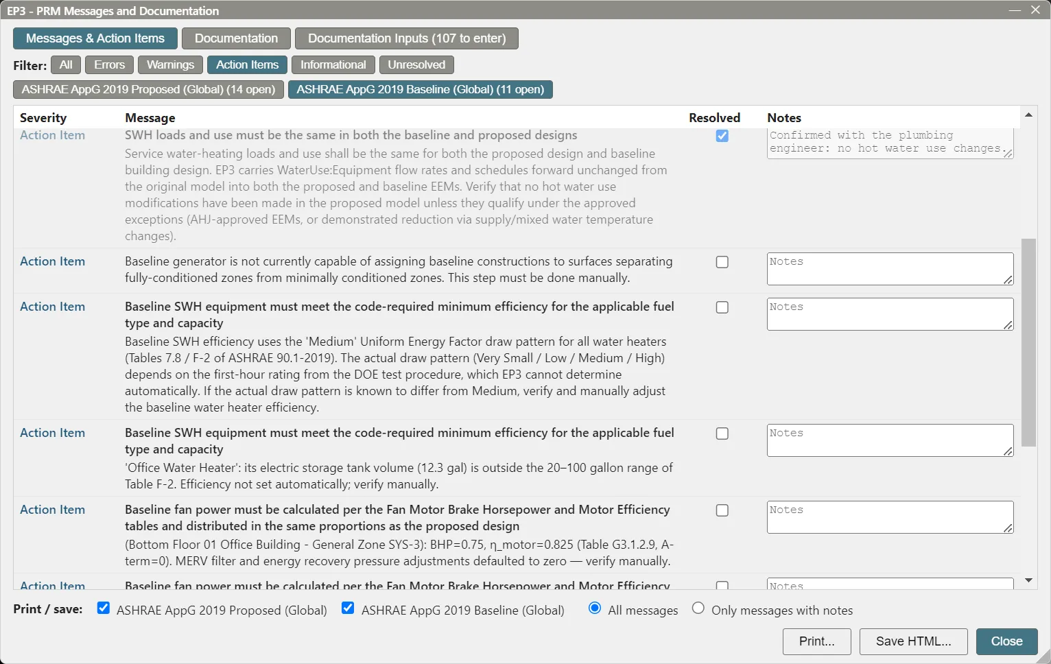
The generator logs four kinds of message for each EEM: Error, Warning, Action Item (something the modeler must check or do), and Informational. Messages are saved on their EEM with the model, also when a run stops.
The PRM Report button (the balance scale with a page behind it, on the toolbar once any EEM has messages or a Baseline exists) opens EP3 - PRM Messages and Documentation. Its Messages & Action Items tab has a tab per EEM, showing its count of open errors, warnings, and action items; filters for each severity and Unresolved; and for each message its requirement, the text, a Resolved checkbox, and Notes. Messages cite the Appendix G section or table they apply, such as Section G3.1.2.10 or, for fan schedules, Table G3.1-4. Print… and Save HTML… take the EEMs ticked under Print / save, with All messages or Only messages with notes.
7. Performance and documentation
This section describes the Appendix G performance cost index. The Energy Cost Budget Method reports the design energy cost against the energy cost budget instead: see §9.9.
7.1 The Documentation tab
The Documentation tab (also the progress dialog’s Documentation button) builds the compliance document for the chosen Baseline EEM from its runs and the model, in IP or SI. Print… prints it and Save HTML… saves one self-contained page. Opened from the toolbar rather than right after a run, it warns that the model may have changed since generation.
7.2 Energy rates
A fuel with a utility tariff in the model is priced by EnergyPlus (Utility Costs). For each fuel the runs use with no tariff, enter a rate (Electricity in $/kWh, Natural Gas in $/therm, most others in $/MMBtu, District Cooling in $/ton-h), or fill every one from Fill from EIA … state averages, which also records EIA as the rate source. A rate (or a source factor, §7.3) is saved when you press Tab or Enter or leave the box; a blank clears it, and text that is not a non-negative number reverts to the saved value. Section G2.4.2 allows actual rates or EIA state averages, not a mix.
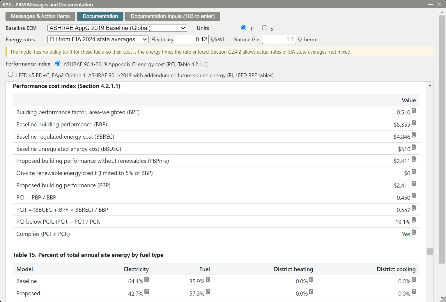
7.3 The performance cost index
The cost of each fuel is split between end uses at its average rate, which separates regulated cost from unregulated cost. Unregulated: interior and exterior equipment (except elevator and escalator subcategories), and any end use subcategory for process or exempt lighting, cooking, IT, or vehicle charging. PRM End-Use Subcategory on ElectricEquipment and a non-General Lighting Purpose on Lights are exported as the End-Use Subcategory, so EnergyPlus reports the split.
Section 4.2.1.1 defines:
PCI = PBP ÷ BBP, and the building complies when PCI ≤ PCIt = (BBUEC + BPF × BBREC) ÷ BBP
where PBP is the Proposed cost, BBP the Baseline cost (averaged over the orientations), BBUEC and BBREC the Baseline’s unregulated and regulated cost, and BPF the Table 4.2.1.1 building performance factor, area-weighted over the segments (unconditioned space included). In 2016 and 2019, on-site renewable energy lowers the Proposed cost by at most 5% of the BBP.
90.1-2022: the renewable energy credit (PRE). Section 4.2.1.1 subtracts PRE from the target: PCIt = (BBUEC + BPF × BBREC − PRE) ÷ BBP, with PRE = PBPnre − PBPpre.
- Required capacity. Section 10.5.1.1 requires 0.50 W/ft² (5.4 W/m²) of on-site renewable capacity for the gross conditioned floor area of the three largest floors (a floor with a multiplier counts as that many floors).
- PBPnre is the Proposed’s cost with its renewable systems off. When the Proposed has a generator, the generator simulates it as a child EEM of the Proposed, “edition Proposed Renewables Off (EEM)”.
- PBPpre is the Proposed with renewable systems of exactly the required capacity, in the same types and proportions as the Proposed’s own (Table 12.5.1 row 15). The generator simulates “edition Proposed Renewables at Required Capacity (EEM)”, with the Proposed’s PVWatts capacities (and the active fraction of simple photovoltaic panels) scaled to the required capacity. When the Proposed has no renewable system, that EEM holds an unshaded reference photovoltaic system instead (Table 12.5.1 item 15(b)): one
Generator:PVWattsof the required capacity, horizontal, facing south, with standard modules on an open rack and 11.3% system losses, written with the automatic load center (Generators). A wind turbine cannot be scaled, so a Proposed with one has its renewable production scaled by capacity instead (output is proportional to rated capacity), and a message says so. - The 5% clause. When the Proposed’s renewable credit beyond the required system’s is more than 5% of the BBP, the test becomes
PCI + (PBPpre − PBP) ÷ BBP − 0.05 ≤ PCIt. The report says which test applies. - Exceptions. Ticking one of the five Section 10.5.1.1 exceptions in the Documentation Inputs, with its reason, sets PRE to 0 (§7.5).
- Short of the requirement. When the Proposed has less than the required capacity and no exception applies, an action item gives the capacity still needed and the result is provisional.
The two renewable energy EEMs are made again on every run and deleted with their Proposed. The reference system is one generator, reused by later runs.
Worked example (PRE). Three largest floors of 16,146 ft² each: 48,438 ft² × 0.50 W/ft² = 24.2 kW required. With no renewable system in the Proposed, the reference system at 24.2 kW produces 30,217 kWh a year in a Washington Dulles weather file; at $0.12/kWh, PRE = 30,217 × $0.12 = $3,626, so PBPpre = PBPnre − $3,626, and PCIt falls by $3,626 ÷ BBP.
Worked example. An office in climate zone 4A (BPF 0.51) with a Baseline of $80,000 regulated and $20,000 unregulated cost, BBP = $100,000:
- PCIt = ($20,000 + 0.51 × $80,000) ÷ $100,000 = ($20,000 + $40,800) ÷ $100,000 = 0.608.
- A Proposed cost of $55,000 gives PCI = 0.550, which is at or below 0.608: it complies.
- Check: the Proposed may cost up to 0.608 × $100,000 = $60,800.
Performance index chooses between that energy cost index and LEED v5 BD+C (EAp2 Option 1, ASHRAE 90.1-2019 with addendum cr), which uses future source energy and LEED’s own BPF tables. Its Source factors default to 2.0 for electricity and 1.0 (site energy) for other fuels, since LEED v5 states only electricity’s; enter others where they apply. A 2016 run offers only the energy cost index: the LEED v5 path is for 90.1-2019, and the LEED v4.1 path is not built yet.
7.4 What the documentation contains
The sections follow the sheets of the LEED Minimum Energy Performance Calculator, filled for the edition you generated (2019 or 2016): Summary, General Information (with the Section G1.3.2 project description), Schedules, Opaque Assemblies, Shading and Fenestration, Lighting, Process Loads, Service Water Heating, General HVAC, Air-Side HVAC, Water-Side HVAC, Performance Outputs (the energy, cost, and unmet hours tables and the performance index), Drawings, and an appendix of the generator’s messages. Every value is marked with its source: simulation, model, generator, user, or computed. Each area’s checklist marks the requirements a generator stage applies, and leaves the rest, including the mandatory provisions of Sections 5.4 to 10.4, for the modeler to answer.
7.5 Documentation Inputs
The Documentation Inputs tab (its label counts the items still to enter) has a collapsible group per section with the values the model cannot supply. Required fields are marked *.
- General Information: project name, address, rating system, location (and zip code or eGRID subregion), energy modeler, the design phase the model is based on, addenda, the Appendix G compliance confirmations, district energy, unfinished spaces, and the narratives Section G1.3.2 requires (project description, key improvements, features less stringent than the prescriptive requirements, modeling assumptions).
- Requirements to confirm: each requirement the generator does not apply, answered Yes, No, or N/A, with a note (for No, the exception). Show requirements already answered shows the answered ones too.
- Quality assurance checks: a response to each check that applies.
- PRM Baseline inputs: the same block as before generation (§3.2), with Save Baseline inputs. When the answers differ from those a Baseline was made with, the group says so and offers Update the Baseline: the Proposed is kept, and the Baseline and its rotations are made again with the new answers and simulated.
- Performance Outputs: the rate structure and utility of each fuel, the rate source, exceptional calculations (Add exceptional calculation: description, fuel, subtract from Proposed or add to Baseline, energy, cost, unregulated), off-site renewable energy, and explanations of simulation warnings and errors. For a 2022 run also: the five Section 10.5.1.1 exceptions (each with a reason), On-site renewable systems calculated outside EP3 (Add renewable system: type, rated capacity, annual production, description, and the annual value in the model’s currency; without a value the production is priced at the Proposed’s average electricity rate, with a warning), and the reference photovoltaic system’s annual production, which replaces the simulated value when entered.
- Drawings: generated from the model; Replace… substitutes your own PNG, JPEG, or SVG, and Restore returns the generated one.
- Compliance Form: <sheet>, one group per sheet of the ASHRAE 90.1 Performance-based Compliance Form: the form’s entries EP3 cannot read from the model with certainty start from EP3’s guess, marked guess (change it, or ↺ to go back to the guess), and the entries that are yours alone (contacts, checklists, fan pressure-drop credits, lighting controls and the rest) are blank until you fill them. Entries the form requires and that are still empty are marked needed, and Save Excel form… lists them before it saves. Find… and Only guesses and needed narrow the list. Each value is entered once: it is saved with the model and written into the form every time it is filled.
Everything entered is saved with the model.
8. What the modeler still enters
This list is for Appendix G. For the Energy Cost Budget Method, see §9.11.
Beyond the inputs of §2 and the documentation inputs of §7.5, the generator leaves these to the modeler, each raised as an action item where it applies:
- humidification and dehumidification in the Baseline (Table G3.1, Section 10);
- fan schedules for health and safety ventilation, computer rooms, and systems simulated only to provide heating or cooling;
- 100% outdoor air for laboratory-only systems, and laboratory, kitchen, and zone exhaust energy recovery exceptions;
- Baseline constructions between conditioned and semiheated spaces;
- Baseline windows that could not be placed at full area;
- design-day profiles of schedules that are not
Schedule:Compact, and lighting shutoff for those schedules; - the retail display lighting allowance, and the quantity of an exterior lighting allowance;
- a fluid economizer for a System 3 or 4 serving a computer room;
- fans in System 9/10 zones that the generator cannot treat as non-mechanical cooling fans, logged as warnings (§5.8); other
ZoneVentilation:DesignFlowRateobjects carry into the Baseline unchanged; - condenser heat recovery for service water heating in 24-hour facilities, which the generator does not check;
- any message the generator logged as an error, which leaves its stage incomplete.
9. The Energy Cost Budget Method (Section 11 and Section 12)
9.1 Choosing a method
ASHRAE 90.1 offers two performance paths. Appendix G compares the Proposed with a Baseline and reports a performance cost index (§7.3). The Energy Cost Budget Method compares the Proposed’s design energy cost with an energy cost budget: it is Section 11 in 90.1-2016 and 2019 and Section 12 in 90.1-2022. Both are valid. Your project’s authority or rating system names the one to use; EP3 does not choose for you.
In the launcher (§3.1), pick one of the three editions under Energy Cost Budget Method (Section 11; Section 12 in 2022). The rest of the flow is the same: validation, the up-front inputs, the existing EEMs step, the progress dialog, PRM Report. EP3 makes a Proposed and a Budget EEM, named “ASHRAE Sec11 ECB 2019 Proposed (Global)” and “ASHRAE Sec11 ECB 2019 Budget (Global)” (Sec12 for 2022). The Budget is a child of the Proposed, as the Baseline is.
An ECB run needs the same preparation as an Appendix G run: climate zone, weather file, Building Segments, and space classifications (§2). The Budget’s lighting and the energy credits read the Building Segments’ building area types and the spaces’ lighting types.
9.2 What the Budget is
The Budget is your Proposed modified as Table 11.5.1 (Table 12.5.1 in 2022) requires. Everything else stays as in the Proposed: geometry, schedules, loads, zoning, outdoor air, the service water heating system type, and the miscellaneous loads.
| Item | The Budget |
|---|---|
| Envelope (item 5) | The Proposed’s heat capacity, with the Section 5.5 prescriptive U-, C- and F-factors for the climate zone and each space’s category (Tables 5.5-0 to 5.5-8): the insulation layer of each construction is resized, and slabs on grade take the F-factor construction. Roof reflectance and emittance as Section 5.5.3.1.1(a) requires. Vertical glazing is reduced in proportion to 40% of the wall area and skylights to 3% of the roof area (Section 5.5.4.2), with the Table 5.5 U-factor and SHGC. No overhangs, fins or insets, no shading devices; the fenestration is flush. |
| Lighting (item 6) | The Section 9 allowance for each space’s lighting type (Table 9.6.1; Tables 9.5.1 and 9.5.2 in 2022), by the space-by-space method. Mandatory Section 9.4.1 controls stay as in the Proposed. The Proposed takes credit for controls beyond Section 9.4.1 (the Table G3.7 occupancy factors x 0.25, or the Table 9.6.3 factors as 1 + CF); the Budget does not. Exterior lighting is the smaller of the Proposed’s power and the Section 9.4.2 allowance, which needs the Exterior Lighting Zone from the Documentation Inputs (§7.5). |
| Service water heating (item 11) | The same system, fuel, input and volume, at the minimum efficiency and standby loss of Table 7.8. |
| HVAC (item 10) | Always from EP3’s budget system library (§9.3): your HVAC is turned off in the Budget, as in Appendix G, and the library system for each zone is turned on. The plants come from the library too. |
| Infiltration | The same in both. In 90.1-2022 the Budget takes 0.35 cfm/ft² at 75 Pa (Section 12.5.3), converted by the Proposed’s own method. |
The library has the eleven systems of Table 11.5.2-1. Each budget system serves the zones of the Proposed system it replaces. Its equipment takes the minimum efficiencies of Section 6.8.1 at the capacities of the Budget’s sizing run (Section 11.5.2(b)), with the Proposed’s sizing factors and no added oversizing (Section 11.5.2(i)). Outdoor air and fan schedules come from the Proposed. Chillers, boilers, towers and pumps follow Tables 11.5.2-2 to 11.5.2-5 and are one shared plant per medium, which often differs from the plants in your design.
Economizers, energy recovery, VAV controls and fan power follow Section 11.5.2(d) to (h) and the notes of Table 11.5.2-1:
- Economizer (Section 6.5.1). EP3 follows the compliance form’s reading in 2016 and 2019: the Budget has an economizer where Table 6.5.1-1 requires one and the Proposed has one. In 2022 the table alone decides.
- Energy recovery (Section 6.5.6.1). Where Table 6.5.6.1-1 or -2 requires it, the Budget has it, unless an exception from the Budget inputs applies.
- VAV systems have a 30% minimum flow and a 5°F supply air temperature reset. EP3 follows the form’s 30% floor in every edition.
- Fan power (Section 11.5.2(h)). Each budget fan system has the Proposed’s brake horsepower per cfm, or the Section 6.5.3.1 limit, whichever is smaller, with the motors of Table 10.8-1. A fan system of 5 bhp or less keeps the Proposed’s power. The 6.5.3.1 limit is raised by the pressure-drop credits you entered (§9.3) and lowered by the Table 6.5.3.1-2 deductions that EP3 reads from the Proposed’s own system: 0.6 in. w.c. for no cooling, 0.3 for no heating, 0.2 for electric resistance heat. Fan speed control follows Section 6.5.3.2.
The Messages of the Budget EEM record each of these decisions with the section or note that sets it.
9.3 Budget inputs before the run
After validation, Budget inputs opens before anything is generated. It is the PRM Baseline inputs step of §3.2 with the Energy Cost Budget questions in place of the Appendix G ones. It has three parts.
Budget HVAC systems (Figure 11.5.2). One row for each conditioned zone shows EP3’s pick for its budget system, a dropdown of the eleven systems of Table 11.5.2-1, and the State:
- automatic: EP3 uses its own pick and works it out again on every run. After the Proposed’s run, EP3 checks the pick against the system the run shows serving the zone, and a difference is noted in the Messages.
- chosen: you picked a system from the dropdown. The pick is kept on a re-run; if the run’s own answer would differ, an informational message says “Your pick is kept”.
- to choose: EP3 has no pick for the zone (ideal loads, evaporative coolers, hybrid units, cooling panels, or equipment it does not recognise). The run asks for a pick through an action item.
EP3 answers Figure 11.5.2’s three questions for each Proposed system: whether the condenser is air or water, whether the heat source is electric resistance, a heat pump or fossil fuel, and whether the system is single-zone residential, single-zone nonresidential or other. The reason above each group of rows gives the answers and the system they lead to, and says whether the Proposed system already is that type. Zones that share a Proposed system form one group, so a VAV loop serving ten zones is one group. A group with several zones has Set every zone here to, and a group with a zone to choose opens by itself. Systems that serve a zone beside its primary system (a DOAS, baseboards, ERVs, exhaust fans) are noted in the reason, not picked as the zone’s system. A zone with no heating or cooling equipment is left out.
Reset on a row returns that zone to EP3’s pick, and Reset all to EP3’s picks at the top does every zone.
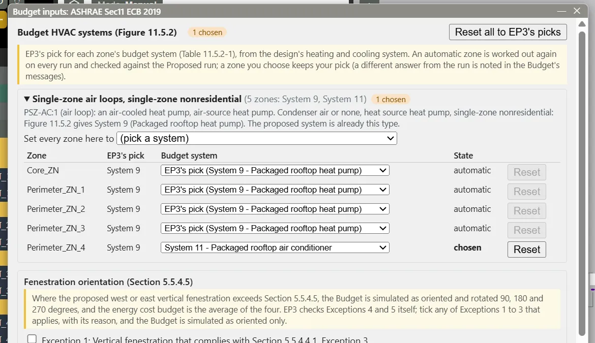
Fenestration orientation (Section 5.5.4.5). See §9.6.
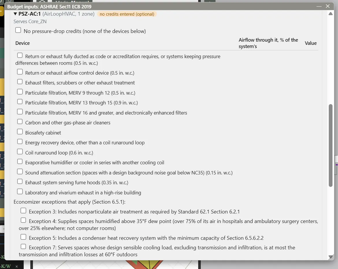
Fan credits and exceptions, per air system. For each air loop and each zone unit with a fan, tick:
- the pressure-drop devices of Table 6.5.3.1-2 the system has, as in §3.2: they raise the Budget’s fan power limit (the A term of Section 6.5.3.1.1). They are optional: a system with none counts none, and the system shows no credits entered (optional).
- the economizer exceptions of Section 6.5.1 that apply (Exceptions 3, 4, 5, 7, 8, 9, 11 and 12; not asked in climate zones 0A, 0B, 1A and 1B, where Table 6.5.1-1 requires no economizer).
- the exhaust air energy recovery exceptions of Section 6.5.6.1 (6.5.6.1.2 in 2019 and 2022) that apply (Exceptions 1, 3, 6, 7 and 8, and 9 from 2019).
The wording of each exception follows the edition you chose. EP3 works out the exceptions that follow from the unit size, the climate zone and the Budget’s efficiencies (economizer Exceptions 1, 2, 6 and 10; energy recovery Exceptions 2, 4 and 5), so they are not asked. Where the model shows evidence (laboratory spaces, supermarket spaces, humidistats, 70% outdoor air), the question starts ticked as EP3’s guess.
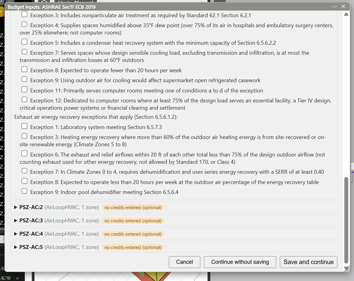
Save and continue saves every answer with the model and goes on; Continue without saving goes on with the answers saved before. The answers appear again under Documentation Inputs (§7.5), where you can change them and make the Budget again with the new answers.
9.4 How EP3 picks the heat source
Figure 11.5.2 asks whether the Proposed system’s heat source is electric resistance, a heat pump or fossil fuel. For each Proposed system, EP3 decides in this order:
- A central heating coil in the air system decides, whatever the reheat is.
- With no central coil but terminal reheat: all electric reheat is electric resistance; hot water reheat follows the boilers on its loop (electric boilers give electric resistance; a fuel boiler, purchased heat, or no boiler found give fossil fuel); mixed reheat is fossil fuel when any coil is.
- No heating at all: fossil fuel, as Table 11.5.1 item 10 requires.
The system’s own heating decides, even where there is gas elsewhere in the building. A VAV loop with hot water reheat and a gas boiler is System 2 (System 4 if packaged); the same loop with electric reheat and no central coil is System 1 (System 3 if packaged). The reason in the Budget inputs says which rule applied, and you override it with the dropdown.
9.5 What a run does
The progress dialog (§3.5) lists the Proposed steps, then the Budget steps: creating the Budget EEM; the envelope, lighting and service water heating (Table 11.5.1 items 5, 6 and 11); determining the budget HVAC systems (Figure 11.5.2); the library systems with their plants; the Budget sizing run, with minimum efficiencies, economizers, energy recovery, VAV controls and plants; fan power; the Budget run; the unmet load hours; the rotations when Section 5.5.4.5 requires them; and saving the messages. A 90.1-2022 run adds the renewable energy runs of §7.3 to the Proposed’s steps.
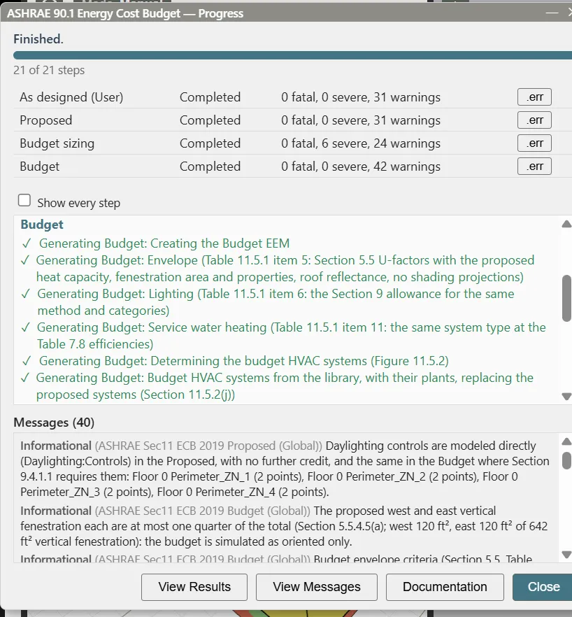
The run list names the Budget’s runs “Budget sizing” and “Budget” (and “Budget rotated N” for each rotation). A sizing-only run can log a few warm-up convergence severe errors; they do not appear in the annual runs.
The run files are in ASHRAE_901_PRM, named as in §3.5: the as-designed run (User), the Proposed, the Budget’s sizing run (Sizing) and the Budget. The Budget has no ideal-loads run. A re-run keeps the model’s size, as in §3.4, and keeps each zone’s pick and your ticked exceptions and credits.
9.6 Rotations
Appendix G rotates the Baseline unless the orientation is dictated by the site. The ECB rotates the Budget only when the Proposed’s west or east vertical fenestration exceeds Section 5.5.4.5: the west and the east fenestration must each be at most a quarter of the total vertical fenestration (Section 5.5.4.5(a)), unless one of the exceptions the section allows applies.
- When the test passes (or does not apply), the Budget is simulated as oriented, and the energy cost budget is its cost. The Messages say so, with the areas: “the proposed west and east vertical fenestration each are at most one quarter of the total (Section 5.5.4.5(a); west 120 ft², east 120 ft² of 642 ft² vertical fenestration)”.
- When it fails, the Budget is simulated at 0, 90, 180 and 270 degrees, the three rotated EEMs together, and the energy cost budget is the average of the four (Table 11.5.1 item 5(c)). The rotated EEMs inherit everything else from the Budget.
- Exceptions. EP3 checks Exceptions 4 and 5 of Section 5.5.4.5 itself. The Fenestration orientation (Section 5.5.4.5) box in the Budget inputs has a checkbox and a reason for each of Exceptions 1 to 3: Exception 1 (vertical fenestration that complies with Section 5.5.4.4.1, Exception 3), Exception 2 (75% of the east and west fenestration shaded by permanent projections, existing buildings, infrastructure or topography at 9 a.m. and 3 p.m. on the summer solstice), and Exception 3 (alterations and additions with no increase in vertical fenestration area). A claimed exception means no rotations, and the Documentation states which one.
9.7 Unmet load hours
Section 11.5.2(i) (12.5.2(i) in 2022) sets two limits on occupied hours with setpoints not met:
- 300 hours or fewer in each model: the Proposed and the Budget (each rotation of the Budget too).
- The Proposed no more than the Budget. With rotations, the Proposed is compared with the average of the rotated Budgets. A Proposed equal to the Budget complies.
How EP3 handles them:
-
The starting model is checked first (§3.3), and the Proposed after its own run.
-
Warm-up schedule fixes (the changes of §5.10: the occupied setpoint and fans starting 1 or 2 hours earlier, or a smaller setback) are tried when the Budget is over 300 hours. They go into both models, because Table 11.5.1 item 4 requires identical schedules; a change that puts the Proposed over 300 is taken out again. A rotation over 300 hours gets the same loop. Your starting model and Global are never changed.
-
Sizing factors are never raised. Section 11 has no provision for it, so the Budget keeps the Proposed’s sizing factors and the Appendix G passes that raise factors by 0.25 do not run. A Budget still over 300 hours gets an action item that says so. It suggests resolving the hours in the design model, which carries over to both, or giving the building official the justification Section 11.5.2(i) asks for.
-
Proposed above the Budget. An action item on both EEMs gives the Proposed’s hours and the Budget’s, lists the zones with more hours in the Proposed (largest difference first, at most ten, each with its main cause), and offers two buttons:
- Show the unmet hours opens the Proposed run’s Unmet Hours tab, which sorts the hours into warm-up, capacity and control (Viewing and Interpreting Results).
- Ask Atlas for help asks the AI assistant, in the Proposed EEM, for the likely causes and fixes (The EP3 AI Assistant).
EP3 never changes your design to bring the Proposed under the Budget. The offer is an action item rather than a question during the run, because once the Budget has been simulated nothing is left for the run to decide.
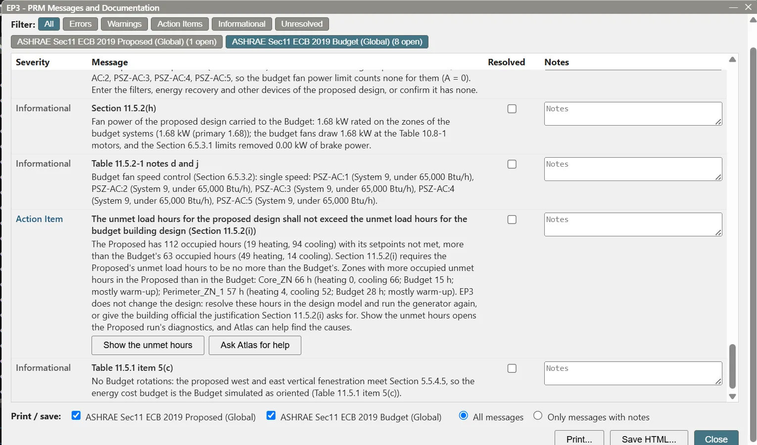
The Documentation’s Table 17 shows each Budget run, the Proposed, and a row Proposed no more than the Budget (Yes or No), with the warm-up notes and the action items after it.
9.8 90.1-2022: energy credits, required photovoltaics, and the envelope check
Section 12 changes the pass test and adds three requirements.
- Energy credits. The Proposed must come in below the budget by a margin set by the energy credits of Table 11.5.1-1: design energy cost ≤ energy cost budget x (1 − ECreq ÷ 1000 x Aadj). ECreq is the credit requirement for the building use types and climate zone, area-weighted over the Building Segments (unconditioned, semiheated and parking areas take 50% of “Other”). Aadj is 1.0 for a new building and, for additions and alterations, the share of the gross floor area that is added or altered. A building with an ECreq of 50 must cost 5% less than its budget.
- Required on-site renewable energy. Section 10.5.1.1 requires on-site renewable capacity, and the budget includes it (Table 12.5.1 item 15): the same type as the Proposed’s, scaled to the required capacity, or the reference photovoltaic system when the Proposed has none. EP3 simulates it as in §7.3 (the Renewables Off and Renewables at Required Capacity EEMs), and the energy cost budget is the Budget’s cost less the value of that required system (PRE). The Proposed’s renewable credit beyond the required system is limited to 5% of the energy cost budget. In 2016 and 2019 the whole credit is limited to 5%.
- Roof area, RAnet. Where the roof cannot take the Table 11.5.1-2 photovoltaic system, Equation 11.5.1 lowers the credits required: ECadj = ECreq − PVadj x (1 − RAnet ÷ (gross floor area x 0.1 W/ft² x 0.20)), with the bracket held at 0 or more. Enter 90.1-2022 Energy Cost Budget: horizontal projection of the available roof area, RAnet (ft2) in the Documentation Inputs (§7.5). Left blank, it means no adjustment. Ticking a Section 10.5.1.1 exception there, with its reason, subtracts the whole PVadj.
- Envelope backstop (Section 12.2(d)). A new building must also meet the Section 5.5 prescriptive envelope, or the Section 5.6 envelope trade-off with the proposed envelope performance factor no more than 15% (multifamily, hotel and motel, dormitory) or 7% (all other types) above the base. The energy model cannot show it. The Documentation lists it in the envelope section’s checklist for you to answer, and the compliance form has its own tables for it (§9.10).
The Documentation’s table shows ECreq, PVadj and the share applied when the roof adjustment changed the credits.
9.9 The pass test and the report
The building complies when:
- The cost test, 2016 and 2019: design energy cost ≤ energy cost budget. In 2022: design energy cost ≤ energy cost budget x (1 − ECreq ÷ 1000 x Aadj), and the envelope backstop is met.
- The unmet-hours test (Section 11.5.2(i), §9.7): 300 hours or fewer in each model, and the Proposed no more than the Budget.
Both must hold. EP3’s verdict is the two together.
The design energy cost is the Proposed’s cost less the on-site renewable credit (at most 5% of the energy cost budget; §9.8 for 2022). The energy cost budget is the Budget’s cost, or the average of its four orientations (§9.6). Both use the same weather and the same energy rates (§7.2), as Section 11.4.3.2 requires. There is no PCI, BPF or PCIt in an ECB result.
The PRM Report button works as in §6 and §7. The Messages tab has a tab for the Proposed and one for the Budget, with citations such as Table 11.5.1 item 6(b) or Section 11.5.2(h). The Documentation tab (its selector reads Budget EEM) has the section Energy Cost Budget Method, Section 11.2(b) (12.2(b) in 2022) in Performance Outputs, with the Proposed’s cost, the renewable credit, the design energy cost, the Budget’s cost, the energy cost budget, and the unmet-hours result, and whether the building complies. Table 17 holds the unmet hours of §9.7.
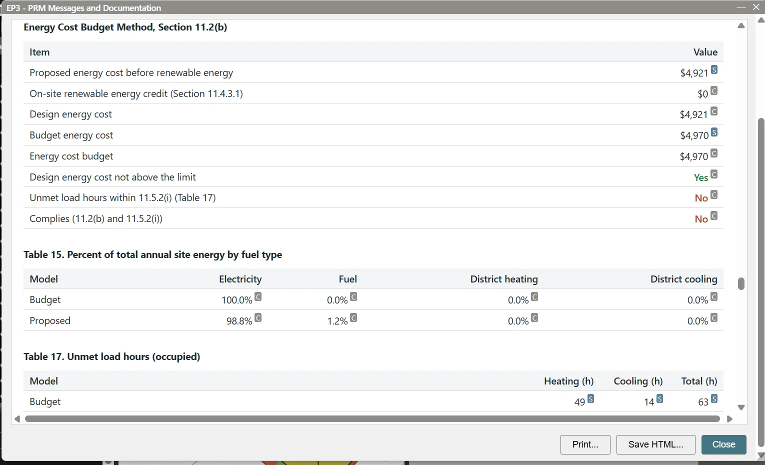
The table has a row for the cost test, a row for the unmet hours (Table 17), and Complies (11.2(b) and 11.5.2(i)), which is Yes only when both hold. The Summary shows the design energy cost against the energy cost budget, with no PCI, and Table 17 agrees with the verdict. In the example above the cost test passes ($4,921 against $4,970), but the Proposed has 112 occupied unmet hours against the Budget’s 63, so the verdict is Does not comply until the action item is resolved.
9.10 The compliance form for Section 11 and 12
The Compliance Form tab of the PRM Report, and Save Excel form…, fill the ASHRAE 90.1 Performance-based Compliance Form (V5.0) for the path you ran (§7.5 describes the entries you supply under Compliance Form: <sheet>). The same workbook serves Appendix G and the Energy Cost Budget Method.
For an ECB run EP3 sets the form’s compliance path to ASHRAE 90.1-2019: Section 11 (Section 12 for 2022), and fills these beside the common sheets:
- Budget HVAC ECB, in place of Baseline HVAC PRM: the Budget’s systems (Table 1a), capacities, fan systems, controls, chillers, boilers and loops. The budget system types, minimum efficiencies, fan power limits and controls are the form’s own formulas; EP3 enters the names, capacities, airflow and plants of the Budget run.
- Envelope Areas: the Section 5.5.4.5 fenestration orientation table, and for 2022 the Section 12.2(d) envelope backstop tables.
- Service Water Heating Table 2: the Budget’s water heaters at their Table 7.8 efficiencies.
- Results from EnergyPlus: the Budget’s run in the “Baseline 0°” block, and the 90, 180 and 270 degree blocks only when Section 5.5.4.5 requires the rotations. The form averages the non-zero blocks.
The form’s Compliance Calculations sheet then computes the design energy cost, the energy cost budget and the verdict in Table 7.
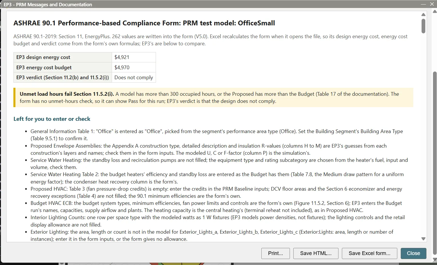
Save Excel form… first lists the entries the form marks required that are still empty, and asks whether to save anyway (Excel shows them in red).
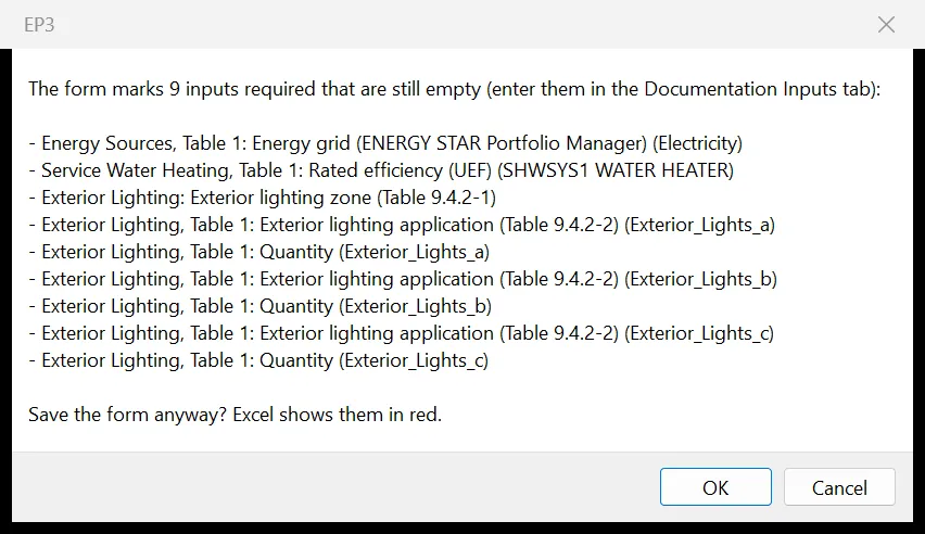
Open the saved file in Excel 2019 or later and enable macros; the form recalculates when it opens, and Excel computes the verdict itself from the values EP3 wrote.
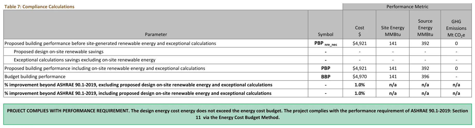

EP3’s own totals were checked against the form’s on a small office and a small hotel. The design energy cost and the energy cost budget matched to the cent, and in 2022 within a few cents (the form values the required photovoltaic production at whole kWh). The form has no unmet-hours check. It tests the cost only, so its Pass can disagree with EP3: on the example above Excel says Pass while EP3 says Does not comply. The tab shows EP3’s design energy cost, energy cost budget (and, in 2022, the credit-adjusted limit) and verdict, with a warning when the unmet hours fail, and the Documentation’s Table 17 holds the hours (§9.7). Rely on EP3’s verdict, and resolve the unmet hours before submitting the form.
Where EP3 and the form differ, EP3 follows the standard. For example, EP3 applies the 9,000 Btu/h capacity rule for residential Systems 8 and 10 that the form applies to System 6 only, and the Messages list the difference.
9.11 What the modeler still enters
Besides the inputs of §8, an ECB run raises these as action items:
- the Exterior Lighting Zone (Table 9.4.2-1), without which exterior lighting stays as proposed;
- the semiexterior envelope, surfaces between conditioned and semiheated spaces, which EP3 does not give budget constructions;
- required skylights (Section 5.5.4.2.3), which EP3 does not add;
- alterations: altered assemblies take the Section 5.1.3 criteria (5.1.4 in 2022), but EP3 models new construction at Section 5.5 and keeps assemblies marked existing;
- the draw pattern of a service water heater rated by a uniform energy factor (EP3 uses the Medium draw pattern), combined space and water heating boilers (Table 11.5.1 item 11, Exception 2), and condenser heat recovery for 24-hour facilities;
- lighting that is a complete system, or not designed, which the Budget keeps as proposed, and the lighting controls beyond Section 9.4.1 that the Proposed has as schedules or daylighting controls and you turn off in the Budget;
- the energy recovery of zone units (Systems 5 to 8 and 10);
- anything the Messages log as an error.
10. Where to Look Next
- Energy Efficiency Measures (EEMs) — how the Proposed, Baseline, and rotated EEMs inherit, and deleting them.
- Generators — photovoltaic generators and load centers, for the Proposed’s own renewable systems.
- EnergyPlus Versions — the model’s EnergyPlus version (PRM needs 23.2 or later).
- Internal Loads, Space Types, and Zone Types — the ASHRAE Space Types tab and the ZoneType’s Building Segment.
- Infiltration, Natural Ventilation and Airflow Networks — the leakage conversion.
- Running Simulations and Viewing and Interpreting Results — the runs and their results.
- Utility Costs — tariffs that price the PRM runs.
- Model Troubleshooting and Quality Assurance — unmet hours and simulation errors.
- Viewing and Interpreting Results — the Unmet Hours tab behind the check in §3.3.
- The EP3 AI Assistant
This handbook is also built into EP3 (Help), where its EnergyPlus links open the EnergyPlus Reference. Technical specifications · Book a demo