Service Hot Water and Solar Water Heating
1. Overview
This chapter covers the service (domestic) hot water side of a model: the water the occupants use, the WaterUse:Connections object that draws it from a plant loop, and the water heaters that heat it. It covers:
- how a service hot water system is assembled, and how the library system arrives as its own EEM (§2);
- the water use itself,
WaterUse:Equipment(§3), andWaterUse:Connections(§4); - storage water heaters,
WaterHeater:MixedandWaterHeater:Stratified(§5), and their sizing object (§6); - heat pump water heaters,
WaterHeater:HeatPump:PumpedCondenserandWaterHeater:HeatPump:WrappedCondenser(§7); - solar water heating and thermal storage, which EP3 does not model (§8);
- the checks that catch a service hot water system that is not doing what you intended (§9).
A service hot water system is a plant loop like any other. Central Plant Equipment and Plant Loops covers plant loops, their branches, pumps, and setpoint managers, and The HVAC Outliner and Creating HVAC Systems covers adding components and connecting them with Draw Branch Connections. This chapter covers what is particular to service hot water.
2. How a service hot water system is put together
A plant-connected service hot water system has four parts:
WaterUse:Equipmentdescribes the fixtures: a peak flow, a schedule, and the temperature delivered at the tap. In EP3 it usually belongs to aZoneType(Internal Loads, Space Types, and Zone Types).WaterUse:ConnectionsgroupsWaterUse:Equipmentobjects and connects them to a plant loop’s demand side. It takes hot water from the loop and returns make-up water from the mains.- A plant loop (a
PlantLoopof the Heating type) with a pump and a setpoint manager. - A water heater on the loop’s supply side: a
WaterHeater:Mixed, aWaterHeater:Stratified, or a heat pump water heater.
A water heater can also serve a draw of its own with no plant loop at all (a stand-alone tank, §5.2).
2.1 The library system
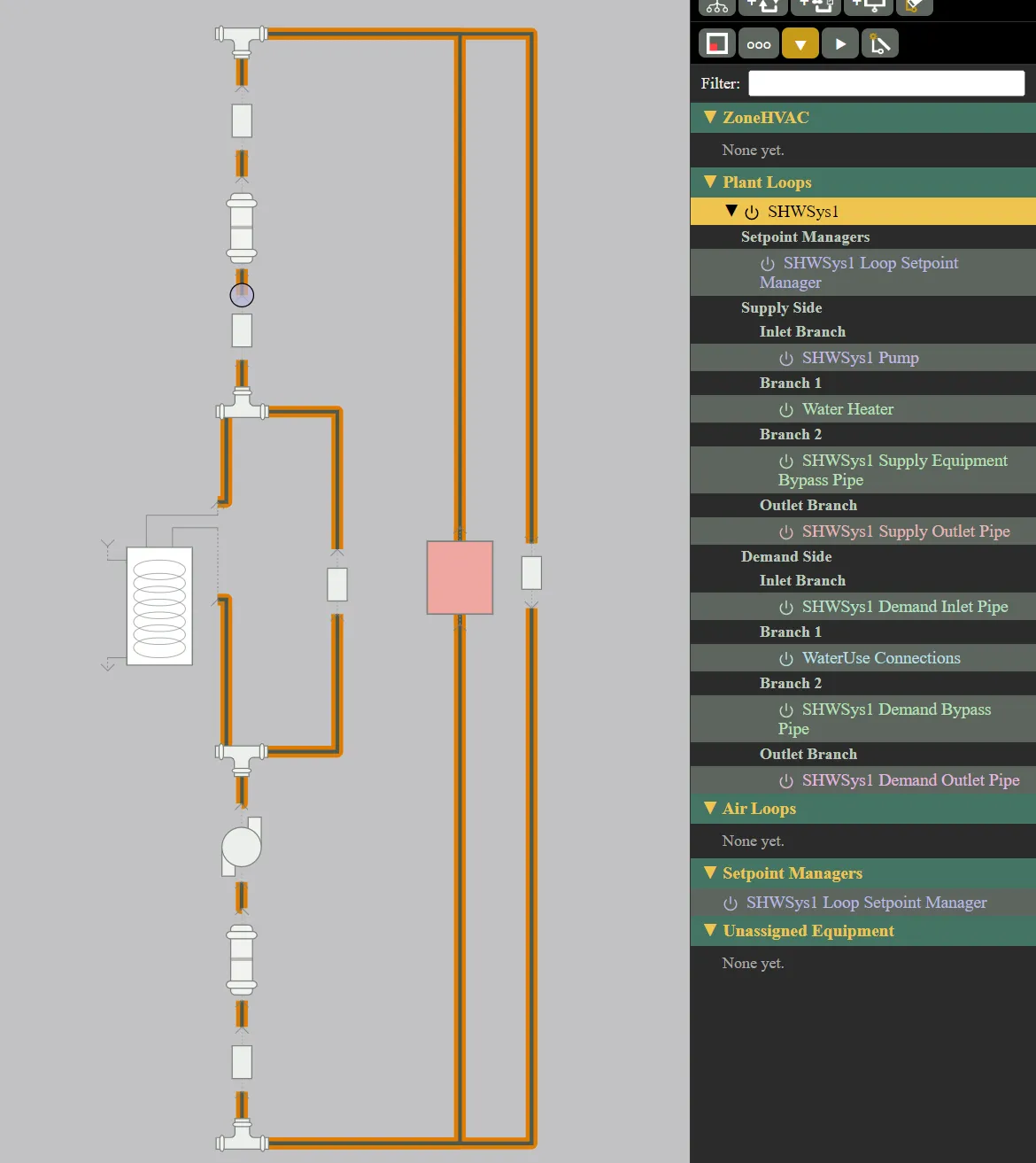
The Model Wizard’s Service Hot Water tab, and the Import dialog’s Library templates tab, offer one complete system from the EP3 Library: WaterHeater with Detailed Connections, an EEM of the HVAC and SWH Systems file under Systems (The Model Wizard). It brings in:
| Object | Name | Settings |
|---|---|---|
PlantLoop with Sizing:Plant |
SHWSys1 | Heating loop; Design Loop Exit Temperature 56°C (132.8°F), Loop Design Temperature Difference 5 K (9°F) |
SetpointManager:Scheduled |
SHWSys1 Loop Setpoint Manager | Holds the supply outlet at the constant 56°C (132.8°F) of SHWSys1-Loop-Temp-Schedule |
Pump:ConstantSpeed |
SHWSys1 Pump | Supply inlet branch; Design Pump Head 179,352 Pa (60 ft of water), Pump Control Type Intermittent |
WaterHeater:Mixed |
Water Heater | Supply side, use side connected; Tank Volume and Heater Maximum Capacity Autosize; DHW Setpoint Schedule at 60°C (140°F); Deadband Temperature Difference 5 K (9°F); electric, Heater Thermal Efficiency 0.95; ambient by schedule at 21°C (69.8°F); Loss Coefficient Input Method LossCoefficientPerVolume at 0.008 W/K per litre (§5.5) |
WaterHeater:Sizing |
(owned by Water Heater) | Design Mode PeakDraw; Time Storage Can Meet Peak Draw 0.538503 hr; Time for Tank Recovery 0.25 hr |
WaterUse:Connections |
WaterUse Connections | Demand side; empty equipment list, so it serves every WaterUse:Equipment in the model (§4.3) |
Site:WaterMainsTemperature |
(unnamed) | Calculation Method CorrelationFromWeatherFile; added only when the model has none |
Because its WaterUse:Connections lists no equipment, the system serves the water use that the Internal Loads templates bring in, with no assignment to make.
The mains temperature is the cold water the heater starts from. Without a Site:WaterMainsTemperature, EnergyPlus holds it at 10°C (50°F) all year. With CorrelationFromWeatherFile it follows the season, from the weather file’s annual average outdoor temperature and the spread of its monthly averages (the correlation of Hendron et al., NREL, which the DOE prototype buildings also use), and lags the outdoor air as buried pipes do. Importing a service hot water system from the library adds one when the model has none; a model’s own Site:WaterMainsTemperature is kept. It is under Location and Climate in the main object dialog.
2.2 Service hot water EEMs
Each service hot water system imported from the library becomes its own Energy Efficiency Measure, named for the template and tagged with the Alternative Category SWH System, with Global as its parent. Its objects are stored in Global, and its EEM is the alternative that switches them on. An SWH EEM starts with Available for Simulation off, because it is a building block: each HVAC system imported afterward chains onto it, so every HVAC alternative carries the water heating system with it (The HVAC Outliner and Creating HVAC Systems). In one Wizard run, service hot water imports before HVAC, so the HVAC EEMs find the SWH EEM selected in the same run. When the model has several SWH EEMs, a new HVAC EEM chains onto the one the existing HVAC EEMs use most.
Each HVAC EEM chains onto one SWH EEM, its parent. Energy Efficiency Measures (EEMs) covers system alternatives, changing an EEM’s parent, and combining EEMs.
2.3 Saving your own service hot water template
A service hot water system you have built is saved the way an HVAC system is, as an .ep3 file in one of your Library Locations (The HVAC Outliner and Creating HVAC Systems). Build it with an EEM active whose Alternative Category is SWH System, so the file offers it on the Service Hot Water tab and it imports as an SWH EEM. Equipment on at Global in no such EEM is offered as one system named Global, on the Service Hot Water tab when it is service hot water equipment.
Leave the template’s WaterUse:Connections list empty, as the library system does, so that the system serves whatever water use the model it is imported into has.
3. Water use: WaterUse:Equipment
3.1 Where it comes from and how it is written
The Internal Loads templates give each ZoneType one WaterUse:Equipment for each hot water fixture its occupants use (§3.2). Internal Loads, Space Types, and Zone Types covers its fields.
EP3 adds a Design Level Calculation Method to WaterUse:Equipment: FlowRate (the default) uses Peak Flow Rate; FlowRatePerPerson uses Peak Flow Rate per Person (m³/s-person, gal/min-person in IP); FlowRatePerArea uses Peak Flow Rate per Area (m³/s-m², gal/min-ft²). The dialog shows only the field the chosen method uses.
At export, EP3 writes one WaterUse:Equipment per zone, named <zone> <name>, each with its own Peak Flow Rate:
- A
ZoneType’sWaterUse:Equipmentis written once for each zone of that type. Any otherWaterUse:Equipmentis written once per zone when its Zone Name is aZoneList, and once when it is aZone. - FlowRate: on a
ZoneList, the figure is the total, shared among the zones by floor area, each zone counted with its multiplier (Floor × Zone), so the multiplied zones together use the total (equally per zone copy, when no zone has floor area). - FlowRatePerPerson: the rate times the zone’s people, from every
Peopleobject in the EEM that covers the zone’s spaces. - FlowRatePerArea: the rate times the zone’s floor area.
A per-person or per-area rate set for one zone, in the ZoneType’s column for that zone, applies to that zone’s copy (Internal Loads, Space Types, and Zone Types). Each figure is for that zone alone; EnergyPlus applies the zone multiplier. A copy whose flow works out to zero (a per-person method in a zone with no people, for example) is written with a zero flow, which can stop EnergyPlus.
3.2 How the library templates set water use
The library templates describe water use the way LEED’s Indoor Water Use Reduction calculation does, so that a water use reduction measure in a LEED submittal and in the energy model start from the same numbers. LEED counts each fixture’s uses per occupant per day, how long each use lasts, and the fixture’s flow rate (LEED v4 BD+C Reference Guide, WE Prerequisite Indoor Water Use Reduction, default fixture uses; LEED v4.1 BD+C keeps the v4 method). The templates take the LEED baseline fixtures (WE Prerequisite Indoor Water Use Reduction, Table 1): 0.5 gal/min (1.9 L/min) public lavatory faucets, 2.2 gal/min (8.3 L/min) private lavatory and kitchen faucets, and 2.5 gal/min (9.5 L/min) showerheads. Toilets and urinals use no hot water and are left out.
Each template has one WaterUse:Equipment per hot water fixture, with End-Use Subcategory Lavatory Faucets, Kitchen Sinks or Showers:
| Occupant (LEED) | Fixture | Uses per day | Duration | Flow | Water at the tap per person per day |
|---|---|---|---|---|---|
| Employee (full-time equivalent) | Lavatory faucet (public) | 3 | 30 s | 0.5 gal/min | 0.75 gal (2.84 L) |
| Kitchen sink | 1 | 15 s | 2.2 gal/min | 0.55 gal (2.08 L) | |
| Shower | 0.1 | 300 s | 2.5 gal/min | 1.25 gal (4.73 L) | |
| Resident | Lavatory faucet (private) | 5 | 60 s | 2.2 gal/min | 11.0 gal (41.6 L) |
| Kitchen sink | 4 | 60 s | 2.2 gal/min | 8.8 gal (33.3 L) | |
| Shower | 1 | 480 s | 2.5 gal/min | 20.0 gal (75.7 L) | |
| Visitor | Lavatory faucet (public) | 0.5 | 30 s | 0.5 gal/min | 0.125 gal (0.47 L) |
| Retail customer | Lavatory faucet (public) | 0.2 | 30 s | 0.5 gal/min | 0.05 gal (0.19 L) |
| Student | Lavatory faucet (public) | 3 | 30 s | 0.5 gal/min | 0.75 gal (2.84 L) |
The uses and durations are LEED’s default fixture uses (USGBC, Water Use Reduction Additional Guidance for LEED 2009, Tables 1 and 2). The LEED v4 Reference Guide keeps them, except that a public lavatory use lasts 30 s where LEED 2009 had 15 s. The shower uses, 0.1 a day of 300 s for an employee and 1 a day of 480 s for a resident, are the LEED 2009 figures. The office templates include showers, which are about half of an office’s water at the tap; delete the Showers equipment for a building without them.
The templates count their People as one of these occupants: employees in Office Building - General, the Space-by-Space Office - Open Plan and Office - Enclosed Space, Light Manufacturing, Warehouse and Health Institutional; residents in Residential Apartments and Hotel (LEED counts hotel guests as residents); visitors in Assembly and Restaurant; retail customers in Retail; students in School and Elementary School. Office - Break and Office - Reception have no water use, since the people counted there are the employees already counted at their desks, or visitors.
Process water. A restaurant’s dishwashing and a hotel’s laundry are process water, which LEED’s fixture calculation does not cover. The Whole Building Restaurant and Hotel templates each have one more WaterUse:Equipment for it, set per floor area and named apart from the fixtures:
| Equipment | End-Use Subcategory | Water per day | Peak Flow Rate per Floor Area |
|---|---|---|---|
| Restaurant Dishwashing | Dishwashing | 4.58 L/m² (0.112 gal/ft²) | 1.6104 × 10⁻⁷ m³/s-m² |
| Hotel Laundry | Laundry | 0.928 L/m² (0.0228 gal/ft²) | 2.7719 × 10⁻⁸ m³/s-m² |
Both come from the U.S. Department of Energy’s ASHRAE Standard 90.1-2019 prototype buildings, as supplied with EnergyPlus: the sit-down restaurant’s dishwasher booster heater draw and the small hotel’s laundry water, each divided by the building’s floor area. The daily volume is spread over the template’s service hot water schedule in the same way as the fixture uses. It is drawn as hot water from the system, with no Target Temperature, since the prototypes supply it at 60°C (140°F), the tank temperature. A dishwasher’s booster heater, which raises the final rinse to about 82°C (180°F), is not included; add one where the kitchen has it. These figures are estimates from one building each: set the dishwashing from the kitchen equipment schedule, and delete the laundry for a hotel that sends its laundry out. A full-service hotel can use several times more laundry water (the large hotel prototype uses 4.6 times as much per floor area).
Water at the tap. Each figure is the water that leaves the tap, hot and cold together. Every fixture has a Target Temperature Schedule Name, the temperature of the water at the tap, and EnergyPlus mixes hot water from the system with mains water to reach it, so the hot share follows the mains temperature through the year. The tap temperatures are 40.6°C (105°F) for hand washing at lavatories (Faucet Target Temperature) and 43.3°C (110°F) for showers (ASHRAE Handbook, HVAC Applications, chapter 51, Service Water Heating, Table 19, Representative Hot-Water Temperatures), and 43.3°C (110°F) for kitchen sinks (Shower and Sink Target Temperature; the sink temperature of the Building America House Simulation Protocols, NREL, Table 9).
Peak flow per person. The daily figure is spread over the full-load hours of the fixture’s schedule on its busiest day: Peak Flow Rate per Person = litres per day ÷ (full-load hours × 3,600 s/hr) ÷ 1,000. LEED’s daily uses are for a day the building operates, and the busiest day of each schedule stands for that day.
A water use reduction measure changes the flow rate of one fixture type, so it changes that fixture’s Peak Flow Rate per Person in the same proportion: a 0.35 gal/min lavatory faucet in place of the 0.5 gal/min baseline is 0.35 ÷ 0.5 = 0.7 times the Lavatory Faucets rate. Set it in the measure’s EEM (Energy Efficiency Measures (EEMs)). A change in the number of uses or their duration scales the rate the same way. ASHRAE Standard 90.1 Appendix G lets the Proposed design show lower service water heating from measures that reduce the volume of water used, such as low-flow showerheads, and from a lower hot water fraction (Table G3.1, item 11, Baseline, exceptions to (h)).
3.3 Worked example: peak flow and heating rate
Office Building - General’s People object allows 25.6 m² (275.6 ft²) per person, the whole-building office density of the ASHRAE Standard 90.1 User’s Manual (Table G-D), and its fixtures use the Office Service Hot Water schedule, 5.38 full-load hours on a weekday. Take an office of 1,500 m² (16,146 ft²) built from this template, with a 60°C (140°F) tank and a mains temperature of 10°C (50°F).
Occupants. 1,500 m² ÷ 25.6 m²/person = 58.59 people. In IP: 16,146 ft² ÷ 275.6 ft²/person = 58.59.
Peak flow per person. Lavatory faucets: 2.839 L ÷ (5.38 hr × 3,600 s/hr) = 1.4659 × 10⁻⁷ m³/s-person (0.002323 gal/min-person). Kitchen sinks: 2.082 L gives 1.0750 × 10⁻⁷ m³/s-person (0.001704 gal/min-person). Showers: 4.732 L gives 2.4431 × 10⁻⁷ m³/s-person (0.003872 gal/min-person).
Peak flow. 58.59 × (1.4659 + 1.0750 + 2.4431) × 10⁻⁷ m³/s = 2.9203 × 10⁻⁵ m³/s (0.0292 L/s). In IP: 58.59 × 0.007899 gal/min = 0.4629 gal/min. Check: 2.9203 × 10⁻⁵ m³/s × 15,850 = 0.4629 gal/min.
Daily use. On a weekday each person draws 9.65 L (2.55 gal) at the tap, 565.6 L (149.4 gal) for the building.
Hot water share. Hot water at 60°C mixed with mains water at 10°C reaches 40.6°C with a hot fraction of (40.6 − 10) ÷ (60 − 10) = 0.611, and 43.3°C with 0.667. At this mains temperature each person draws 6.28 L (1.66 gal) of hot water on a weekday. A warmer mains temperature lowers the hot share.
Heating rate at peak flow. The heat added is each fixture’s flow times the rise from the mains to its tap temperature:
Q = ρ · cp · Σ V̇ · (Ttap − Tcold) = 1,000 kg/m³ × 4,180 J/kg·K × (8.5893 × 10⁻⁶ × 30.56 + 6.2988 × 10⁻⁶ × 33.33 + 1.4315 × 10⁻⁵ × 33.33) m³·K/s = 3,969 W ≈ 3.97 kW
In IP, with Q [Btu/h] = 500 × gal/min × ΔT [°F]: 500 × (0.1361 × 55 + 0.0998 × 60 + 0.2269 × 60) = 13,544 Btu/h = 3.97 kW. The same heat, worked from the hot water alone: 1.8992 × 10⁻⁵ m³/s of hot water × 4,180 × 1,000 × (60 − 10) = 3,969 W.
The Office Service Hot Water schedule peaks at 0.57 of this flow on weekdays, so the largest scheduled draw is 0.57 × 3.97 kW = 2.26 kW (7,720 Btu/h) before tank and piping losses and the water heater’s efficiency.
A WaterUse:Equipment without a Target Temperature Schedule Name draws hot water only (or, when stand-alone with no hot water supply temperature, cold water only). A published figure given as hot water rather than water at the tap belongs on equipment without a target temperature.
3.4 Water use with no water heater
WaterUse:Equipment that no WaterUse:Connections lists is simulated stand-alone. It heats water only when it has a Hot Water Supply Temperature Schedule Name; when that field is blank, hot water follows the cold water temperature and the equipment uses cold water only. Stand-alone equipment that does heat water reports that heat as purchased heating, with no water heater, losses, or efficiency. The library templates leave the hot water supply temperature blank, so a model with no water heating system reports water volume under Water Systems and no water heating energy (The Model Wizard).
4. WaterUse:Connections
4.1 Adding and connecting
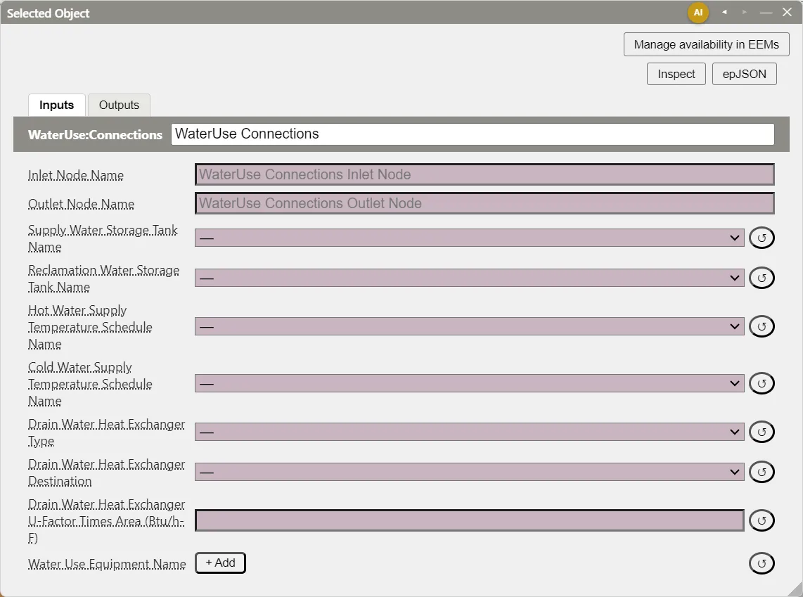
WaterUse:Connections is under Plant Equipment in EP3 - HVAC Components (The HVAC Outliner and Creating HVAC Systems). It has one node pair, Inlet Node Name and Outlet Node Name, and connects only to the demand side of a Heating, Cooling, Condenser, or Steam loop. With Draw Branch Connections, connect it to a demand splitter or mixer port to give it a branch of its own (The HVAC Outliner and Creating HVAC Systems). It is drawn with the generic equipment symbol.
The inlet takes hot water from the loop; the outlet returns make-up water at the mains temperature, replacing the water that went down the drain. While it is on a plant loop, the loop’s water temperature at its inlet replaces the hot water supply temperature of every piece of equipment it lists.
4.2 Fields
| Field | Purpose |
|---|---|
| Supply Water Storage Tank Name, Reclamation Water Storage Tank Name | WaterUse:Storage tanks for cold water supply and graywater. EP3 has no WaterUse:Storage object, so leave these blank: cold water comes from the mains and graywater is not reclaimed. |
| Hot Water Supply Temperature Schedule Name | Used only when the connection is on no plant loop. |
| Cold Water Supply Temperature Schedule Name | The mains temperature for every listed piece of equipment; from Site:WaterMainsTemperature when blank. |
| Drain Water Heat Exchanger Type | None (default), Ideal, CounterFlow, or CrossFlow: drainwater heat recovery. |
| Drain Water Heat Exchanger Destination | Plant (default), Equipment, or PlantAndEquipment: where the recovered heat goes. |
| Drain Water Heat Exchanger U-Factor Times Area | The heat exchanger’s UA, for CounterFlow and CrossFlow. |
| Water Use Equipment Name | The list of WaterUse:Equipment this connection serves; + Add adds a row. |
List the WaterUse:Equipment objects as they appear in the model, not their per-zone copies: at export, each listed object becomes one entry per zone copy. An object that is off in the EEM is left off the list. To give some zones’ copies to one connection and the rest to another, use the Water Use Connections dialog (§4.4).
4.3 Automatic equipment assignment
When a WaterUse:Connections lists no equipment, EP3 assigns it every WaterUse:Equipment copy in the EEM that no other WaterUse:Connections lists. EnergyPlus has no such rule; EP3 fills in the list at export. A model with one service hot water system therefore needs no assignment.
With two or more systems, assignment has to be explicit. When more than one WaterUse:Connections has an empty list, EP3 cannot tell which system an unlisted piece of equipment belongs to, so only the first of them by name takes the unlisted equipment. Each of the others is exported with no equipment, and the export reports an error naming the connection that took it. Equipment listed by two connections is written to both, and its water is counted twice. To divide the water use between systems, list each system’s equipment in its Water Use Equipment Name rows, or assign the copies in the Water Use Connections dialog (§4.4).
4.4 Assigning copies by zone
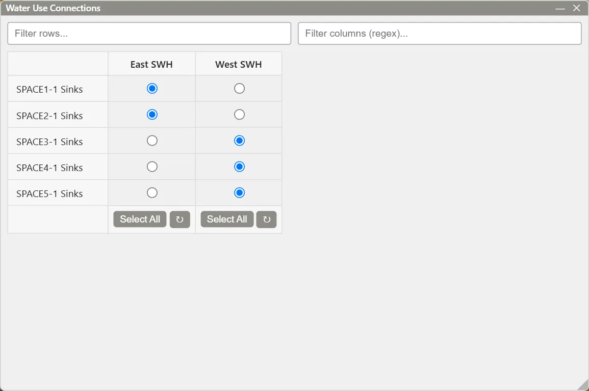
A WaterUse:Equipment owned by a ZoneType, or assigned to a ZoneList, is written once per zone. Its copies can be drawn by different connections, such as one ZoneType’s restroom sinks on the plant loop of each floor. Assign water use by zone… on a WaterUse:Connections dialog, or Assign to WaterUse:Connections by zone… on a WaterUse:Equipment, opens the Water Use Connections dialog for the active EEM:
- one row per copy, named as the export names it (
<zone> <equipment>), and one column perWaterUse:Connectionson in the EEM; - a radio button in each cell: pick one to put that copy on that connection and take it off the others;
- Filter rows… and Filter columns (regex)… narrow the grid, and each column’s Select All puts every row shown on that connection, while ↻ puts back the rows shown that were on it when the dialog opened. The row and column names stay in view as the grid scrolls;
- a copy that no connection lists is marked adopted on the connection that takes it (§4.3), and a column whose list is empty says adopts unlisted. A copy listed by two connections says so beside its name.
A connection that ends up with every copy of an equipment lists the equipment whole, as before; one with some of them keeps them as equipment-and-zone pairs, which the export expands to exactly those copies. The Combine dialog keeps each zone’s copy on the connection that drew it when it combines water use into a ZoneType (Internal Loads, Space Types, and Zone Types).
5. Water heaters: WaterHeater:Mixed and WaterHeater:Stratified
5.1 The two tank models
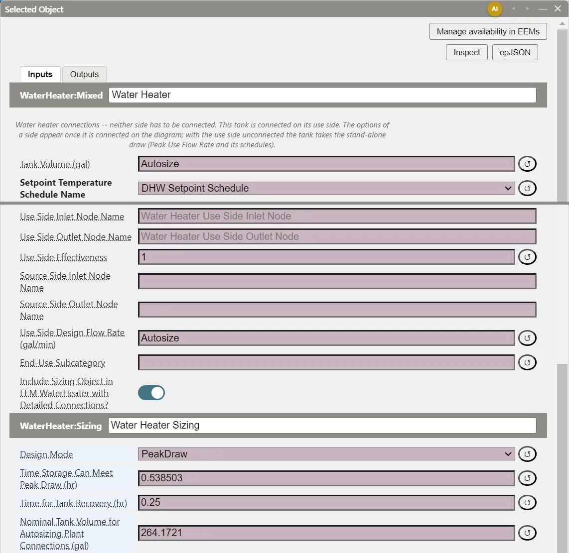
WaterHeater:Mixed models the tank as one well-mixed volume at a single temperature, with one heater controlled by Setpoint Temperature Schedule Name, Deadband Temperature Difference, and Heater Control Type (Cycle or Modulate).
WaterHeater:Stratified divides the tank into a vertical stack of nodes (Number of Nodes, up to 12, each with its Node N Additional Loss Coefficient), with two heaters at set heights. Each heater has its setpoint schedule, deadband, capacity, and height, and Heater Priority Control chooses MasterSlave (the default: heater 2 runs only while heater 1 is off) or Simultaneous. Its geometry fields are Tank Height, Tank Shape, and Tank Perimeter, which is shown only for Tank Shape Other.
,
Both are under Service Hot Water in EP3 - HVAC Components. A new tank starts with Heater Fuel Type Electricity, Heater Thermal Efficiency 0.95, Ambient Temperature Indicator Zone, and its standby loss given per litre of tank (§5.5). EP3 creates no setpoint schedule for it: choose or create one for Setpoint Temperature Schedule Name (or the two heater setpoint schedules of a stratified tank), or the Validation dialog’s Required Fields tab reports the tank. A new WaterHeater:Mixed has a Tank Volume of 0, EnergyPlus’s default, which models an instantaneous heater; enter a volume or Autosize it.
The tank is drawn with the water heater symbol: the use side’s two nodes on its right and the source side’s two nodes on its left.
5.2 Use side and source side
A water heater has two node pairs, and neither has to be connected:
- the use side (Use Side Inlet Node Name, Use Side Outlet Node Name) delivers hot water to whatever draws it;
- the source side (Source Side Inlet Node Name, Source Side Outlet Node Name) takes heat into the tank from another loop, in addition to or in place of its heater.
Each pair connects to a Heating loop, on its supply or its demand side. A tank is plant equipment of a loop, listed in the loop’s equipment list, only through a pair on that loop’s supply side. The usual arrangements are:
| Arrangement | Use side | Source side |
|---|---|---|
| Direct-fired or electric tank serving a hot water loop (the library system) | Supply side of the service hot water loop | Not connected |
| Indirect tank heated by a boiler loop | Supply side of the service hot water loop | Demand side of the boiler’s hot water loop |
| Stand-alone tank | Not connected | Not connected |
A stand-alone tank sits under Unassigned Equipment in the HVAC Outliner and is exported with blank node fields. It serves the draw described by its Peak Use Flow Rate, Use Flow Rate Fraction Schedule Name, and Cold Water Supply Temperature Schedule Name; no WaterUse:Equipment can draw from it.
5.3 Options that follow the connections
The tank’s dialog opens with a note naming the sides that are connected, and shows the fields those connections use:
| Connections | Fields shown |
|---|---|
| Use side connected | Use Side Effectiveness, Use Side Design Flow Rate; on a stratified tank, Use Side Inlet Height and Use Side Outlet Height |
| Use side not connected | Peak Use Flow Rate, Use Flow Rate Fraction Schedule Name, Cold Water Supply Temperature Schedule Name |
| Source side connected | Source Side Effectiveness, Source Side Design Flow Rate, Indirect Water Heating Recovery Time, Source Side Flow Control Mode; Indirect Alternate Setpoint Temperature Schedule Name while the mode is IndirectHeatAlternateSetpoint; on a stratified tank, Source Side Inlet Height and Source Side Outlet Height |
| Either side connected (stratified tank) | Inlet Mode |
Connections can differ by EEM (Air Loops, Branches, and Nodes), and the dialog follows the connections of the active EEM. A hidden field keeps its value, and the value is still exported, so connecting a side again brings back what was entered for it.
5.4 Ambient temperature
Ambient Temperature Indicator sets the temperature the tank loses heat to, and the dialog shows only the field it uses:
- Zone — Ambient Temperature Zone Name. The tank’s skin losses, in the fractions set by Off Cycle Loss Fraction to Zone and On Cycle Loss Fraction to Zone (Skin Loss Fraction to Zone and Off Cycle Flue Loss Fraction to Zone on a stratified tank), are added to that zone as a heat gain.
- Schedule — Ambient Temperature Schedule Name. The library system uses a constant 21°C (69.8°F) schedule.
- Outdoors — no field to fill in. EP3 writes
<tank> OA Nodeinto the tank’s outdoor air node field and declares that node in anOutdoorAir:NodeList.
5.5 Standby loss
A tank loses heat through its skin to its surroundings, at a rate set by its loss coefficient (W/K) times the difference between the tank and ambient temperatures. EnergyPlus has no default loss coefficient: a tank left without one has no standby loss.
A tank’s loss grows with its size, and an autosized tank’s size is known only once EnergyPlus has run, so EP3 adds a Loss Coefficient Input Method:
- LossCoefficient (the default for a tank from a file): the tank’s own Off Cycle Loss Coefficient to Ambient Temperature and On Cycle Loss Coefficient to Ambient Temperature (on a stratified tank, Uniform Skin Loss Coefficient per Unit Area to Ambient Temperature).
- LossCoefficientPerVolume (a new tank, and the library system): Loss Coefficient per Tank Volume, in W/K per litre (Btu/h-°F per gallon in IP). The dialog hides the EnergyPlus loss coefficient fields, and the export writes them as this figure times the tank’s volume: the Tank Volume, or for an autosized tank the volume its
WaterHeater:Sizinggives (§6.2). A stratified tank’s skin loss coefficient is that loss over the tank’s surface, from its volume, shape and height (for an autosized height, the sizing object’s Height Aspect Ratio).
The default, 0.008 W/K per litre (0.0575 Btu/h-°F per gallon), is the 40 gal (151 L) electric storage water heater of the DOE/PNNL ASHRAE 90.1-2019 Small Office prototype: 1.206 W/K, from the federal minimum Energy Factor of 0.97 − 0.00132 × gallons. A gas-fired tank loses more through its flue: the prototypes’ gas tanks have 0.007 to 0.027 W/K per litre. When a sized tank’s volume cannot be worked out (sizing per solar collector area, or a use side that is not on a plant loop’s supply side), the export warns and writes no loss coefficient.
Worked example. The library system serving the office of §3.3 sizes a 56.61 L (14.96 gal) tank (§6.3). Its loss coefficient is 0.008 W/K per L × 56.61 L = 0.453 W/K (0.860 Btu/h-°F). Held at 60°C in its 21°C ambient, it loses 0.453 × (60 − 21) = 17.7 W (60.3 Btu/h), about 155 kWh (529 kBtu) a year.
6. Sizing the tank: WaterHeater:Sizing
A tank whose Tank Volume or Heater Maximum Capacity (or a stratified tank’s Tank Height) is Autosize needs a WaterHeater:Sizing object that tells EnergyPlus how to size it.
6.1 Including the sizing object in an EEM
The last row of a tank’s dialog is Include Sizing Object in EEM <name>?, a switch, where <name> is the active EEM. Turning it on the first time creates the tank’s WaterHeater:Sizing and shows its fields below the tank’s. The sizing object belongs to the tank: it has no outliner row, its WaterHeater Name is filled in by EP3 (and follows a rename), and it is copied and deleted with the tank.
The switch is stored per EEM, so one EEM can autosize a tank while another gives it fixed values. Turning it off leaves the sizing object and its values in place, and the sizing object is written only in the EEMs that include it. An imported file’s WaterHeater:Sizing is attached to the tank it names and renamed <tank name> Sizing, with the switch on for the import, which is how the library system’s tank arrives with its sizing object included.
6.2 Design modes
| Design Mode | Fields used | Tank volume | Heater capacity |
|---|---|---|---|
PeakDraw |
Time Storage Can Meet Peak Draw, Time for Tank Recovery, Nominal Tank Volume for Autosizing Plant Connections | Peak draw flow × storage time | The volume heated from 14.4°C to 57.2°C (58°F to 135°F) in the recovery time |
PerPerson |
Storage Capacity per Person, Recovery Capacity per Person | Rate × the people in the whole model | Recovery rate × people, heated 14.4°C to 57.2°C |
PerFloorArea |
Storage Capacity per Floor Area, Recovery Capacity per Floor Area | Rate × the floor area of the whole model | Recovery rate × floor area, heated 14.4°C to 57.2°C |
PerUnit |
Number of Units, Storage Capacity per Unit, Recovery Capacity PerUnit | Rate × number of units | Recovery rate × units, heated 14.4°C to 57.2°C |
ResidentialHUD-FHAMinimum |
Number of Bedrooms, Number of Bathrooms | From the HUD-FHA minimum table | From the same table |
PerSolarCollectorArea |
Storage Capacity per Collector Area | Rate × the area of the model’s solar collectors | Zero |
Height Aspect Ratio sizes the height of a stratified, vertical-cylinder tank from its volume. The sizing object’s dialog shows every field whatever the design mode; fill in the ones the mode uses. PerPerson and PerFloorArea size every tank for the whole building, so in a model with more than one water heater each one is sized for the total. PerSolarCollectorArea needs a solar collector, which EP3 does not model (§8).
6.3 Worked example: PeakDraw
For a tank on the supply side of a plant loop, the peak draw is the tank’s Use Side Design Flow Rate, which autosizes to the design flow of the loop’s demand side. For the library system serving the office of §3.3, that is the fixtures’ peak flow, 2.9203 × 10⁻⁵ m³/s (0.4629 gal/min). The library’s WaterHeater:Sizing has Time Storage Can Meet Peak Draw 0.538503 hr and Time for Tank Recovery 0.25 hr.
Tank volume = draw × time: 2.9203 × 10⁻⁵ m³/s × 0.538503 hr × 3,600 s/hr = 0.05661 m³ (56.61 L). In IP: 0.4629 gal/min × 0.538503 hr × 60 min/hr = 14.96 gal. Check: 0.05661 m³ × 264.17 gal/m³ = 14.96 gal.
Heater capacity = the energy to heat that volume from 14.4°C to 57.2°C, delivered in the recovery time:
q = V · ρ · cp · (57.2 − 14.4) ÷ trecovery = 0.05661 m³ × 1,000 kg/m³ × 4,180 J/kg·K × 42.8 K ÷ (0.25 hr × 3,600 s/hr) = 11,254 W ≈ 11.3 kW
In IP, the rise is 77.04°F: 14.96 gal × 8.34 lb/gal × 1 Btu/lb·°F × 77.04°F ÷ 0.25 hr = 38,437 Btu/h = 11.3 kW, which agrees within the rounding of the water properties.
The 15-minute recovery time is what makes the heater large: recovering the same tank in one hour would need a quarter of the capacity, 2.81 kW (9,600 Btu/h). EnergyPlus evaluates water’s density and specific heat at reference temperatures of its choosing, so the sized values it reports in the .eio file and the component sizing summary differ slightly from these.
6.4 Worked example: PerPerson
A design guide calls for 0.75 gal/person of storage and 0.25 gal/hr-person of recovery, entered as Storage Capacity per Person and Recovery Capacity per Person. In SI these are 0.002839 m³/person (2.839 L) and 0.0009464 m³/hr-person (0.9464 L/hr). The office of §3.3 has 58.59 people.
Tank volume: 58.59 × 0.75 gal = 43.95 gal. In SI: 58.59 × 2.839 L = 166.3 L = 43.95 gal.
Heater capacity: the recovery rate is 58.59 × 0.25 = 14.65 gal/hr, heated 77.04°F: 14.65 × 8.34 × 77.04 = 9,412 Btu/h = 2.76 kW. In SI: 58.59 × 0.0009464 m³/hr × 1,000 kg/m³ × 4,180 J/kg·K × 42.8 K ÷ 3,600 s/hr = 2,756 W.
7. Heat pump water heaters
7.1 Pumped and Wrapped
A heat pump water heater is a composite: a parent object that owns a tank, a DX water heating coil, and a fan, the same arrangement as the composite zone units in Zone-Level HVAC Equipment and Zone Sizing. Both types are under Service Hot Water in EP3 - HVAC Components.
| Slot | WaterHeater:HeatPump:PumpedCondenser |
WaterHeater:HeatPump:WrappedCondenser |
|---|---|---|
| Water Heater Tank | WaterHeater:Mixed (default) or WaterHeater:Stratified |
WaterHeater:Stratified |
| DX Coil | Coil:WaterHeating:AirToWaterHeatPump:Pumped (default) or Coil:WaterHeating:AirToWaterHeatPump:VariableSpeed |
Coil:WaterHeating:AirToWaterHeatPump:Wrapped |
| Fan | Fan:OnOff (default) or Fan:SystemModel |
Fan:OnOff (default) or Fan:SystemModel |
In the Pumped type, a pump circulates tank water through the coil’s condenser: EP3 joins the coil’s condenser water nodes to the tank’s source side inside the unit, and that loop is never on a plant loop. In the Wrapped type, the condenser is wrapped around the tank and heats it through the tank wall, so there are no condenser water nodes and the tank’s source side is blank.
A new coil starts with the performance curves and rated capacity of the EnergyPlus example files. These coils cannot be autosized, so replace the example’s rated capacity with the equipment’s. A new tank starts as a stand-alone tank does (§5.1).
7.2 The unit’s dialog
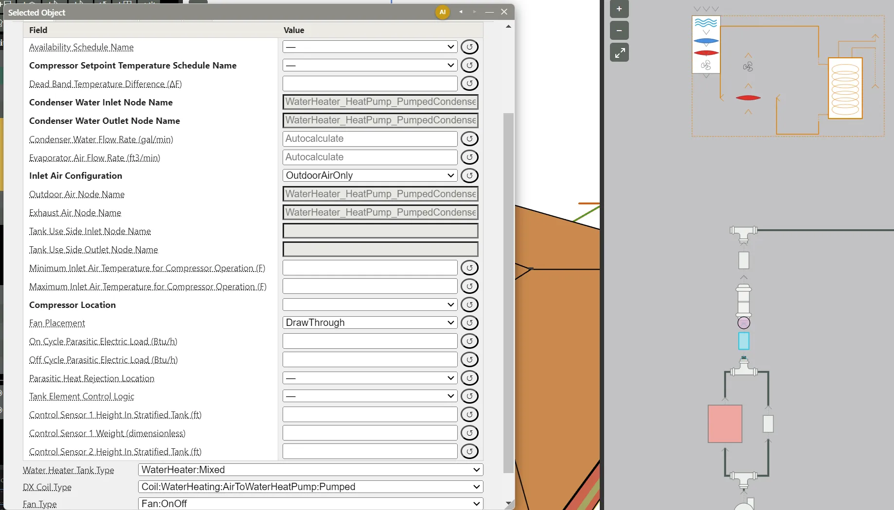
The dialog has a Unit tab, then Water Heater Tank, DX Coil, and Fan tabs. The Unit tab holds the parent’s fields and the Water Heater Tank Type, DX Coil Type, and Fan Type rows that choose each slot’s class, per EEM (Zone-Level HVAC Equipment and Zone Sizing). The Water Heater Tank tab ends with the tank’s Include Sizing Object in EEM <name>? switch; turning it on adds a Water Heater Tank Sizing tab with the tank’s WaterHeater:Sizing (§6.1).
The compressor’s controls are on the Unit tab:
- Compressor Setpoint Temperature Schedule Name and Dead Band Temperature Difference (default 5 K, 9°F) set the band the compressor cycles in. Set the compressor setpoint above the tank’s heater setpoint, so the heat pump runs first and the tank’s element serves as backup.
- Minimum Inlet Air Temperature for Compressor Operation and Maximum Inlet Air Temperature for Compressor Operation (defaults 10°C and 48.9°C, 50°F and 120°F) lock the compressor out when the inlet air is outside that range.
- Tank Element Control Logic chooses
Simultaneous(the default: the element and the compressor can run together) orMutuallyExclusive(the element runs only while the compressor is off). - Compressor Location (
Schedule,Zone, orOutdoors) sets the temperature around the compressor; Compressor Ambient Temperature Schedule Name is shown only forSchedule. Parasitic Heat Rejection Location (ZoneorOutdoors) sets where the parasitic loads’ heat goes.Zonefor either requires a configuration that takes zone air (§7.3). - With a stratified tank, Control Sensor 1 Height In Stratified Tank and Control Sensor 2 Height In Stratified Tank, with their weights, set where the heat pump reads the tank temperature.
7.3 Inlet air configuration and fan placement
Inlet Air Configuration decides where the evaporator’s air comes from and goes, and Fan Placement (DrawThrough, the default, or BlowThrough) puts the fan after or before the coil. EP3 wires the unit’s air nodes for the combination and hides the node and schedule fields the combination does not use:
| Inlet Air Configuration | Air path | Fields it uses |
|---|---|---|
OutdoorAirOnly (the default) |
Outdoor air node to exhaust air node | — |
Schedule |
Air inlet node to air outlet node, at scheduled conditions | Inlet Air Temperature Schedule Name, Inlet Air Humidity Schedule Name |
ZoneAirOnly |
From a zone exhaust node back to a zone inlet node | The zone it serves (§7.4) |
ZoneAndOutdoorAir |
A mix of zone and outdoor air, through an inlet air mixer and an outlet air splitter | Inlet Air Mixer Schedule Name (0 = all zone air, 1 = all outdoor air) |
The outdoor air nodes are declared in an OutdoorAir:NodeList at export.
7.4 Heat pump water heaters that use zone air
While Inlet Air Configuration is ZoneAirOnly or ZoneAndOutdoorAir, the unit is zone equipment. It appears as a chip in EP3 - Select Zone Conditioning Equipment, and is assigned to zones there like any other zone unit (Zone-Level HVAC Equipment and Zone Sizing). EP3 writes one copy per zone that lists it: the parent, tank, coil, and fan each named <zone> <name>, with Inlet Air Zone Name set to that zone, and the unit’s air nodes in the zone’s inlet and exhaust node lists. A zone served this way needs no thermostat for the unit.
The plant branch the unit sits on is copied per zone too, so the loop gets one parallel branch per copy, and the unit must be alone on its branch (Zone-Level HVAC Equipment and Zone Sizing). A zone-air unit that no zone lists is not exported.
With the other configurations the unit is not zone equipment: it is written once, whether or not it is on a loop, and any zone assignments it had are kept for when the configuration changes back. The configuration can differ by EEM.
7.5 The plant connection
The unit’s only plant connection is its tank’s use side, through the parent’s Tank Use Side Inlet Node Name and Tank Use Side Outlet Node Name. It connects to the supply side of a Heating loop and is optional: a unit on no loop serves its tank’s stand-alone draw (Peak Use Flow Rate on the Water Heater Tank tab). On a loop, the branch and the loop’s equipment list name the heat pump water heater, not its tank.
7.6 Integrated heat pump
A Pumped heat pump water heater can be part of an integrated heat pump (CoilSystem:IntegratedHeatPump:AirSource): one air-source heat pump that heats water for the tank and also heats and cools a space through an air loop’s unitary system. Use Integrated Heat Pump on the Unit tab can be set to Yes only while:
- the unit is the Pumped type;
- its DX Coil Type is
Coil:WaterHeating:AirToWaterHeatPump:VariableSpeed; - its Inlet Air Configuration is
OutdoorAirOnlyorSchedule.
Yes adds Space Cooling Coil and Space Heating Coil, which list the Coil:Cooling:DX:VariableSpeed and Coil:Heating:DX:VariableSpeed coils of the model’s AirLoopHVAC:UnitarySystem and AirLoopHVAC:UnitaryHeatPump:AirToAir objects. When the chosen coil’s air loop is replicated, a Space Cooling Coil Replicate or Space Heating Coil Replicate row picks the replicate. EP3 creates the integrated heat pump object and the five additional coils it needs, with the EnergyPlus example curves, and at export the unitary system names the integrated heat pump as its heating and cooling coil. Setting the choice back to No keeps those objects for later. The choice is stored per EEM, so an EEM can test the integrated heat pump against a separate water heater and space heat pump.
8. Solar water heating and thermal storage
EP3 does not model solar water heating. It has no SolarCollector:* object types, and a file imported with solar collectors does not bring them in (Importing EnergyPlus Files). The PerSolarCollectorArea sizing mode (§6.2) therefore has no use in an EP3 model. For collector models, see the EnergyPlus documentation.
EP3 also has no thermal storage tanks (ThermalStorage:ChilledWater:*, ThermalStorage:HotWater:Stratified, ThermalStorage:Ice:*). An imported file’s storage tank is not imported, and the plant loop that holds it is not imported either; the Import Report lists both.
9. Checking a service hot water system
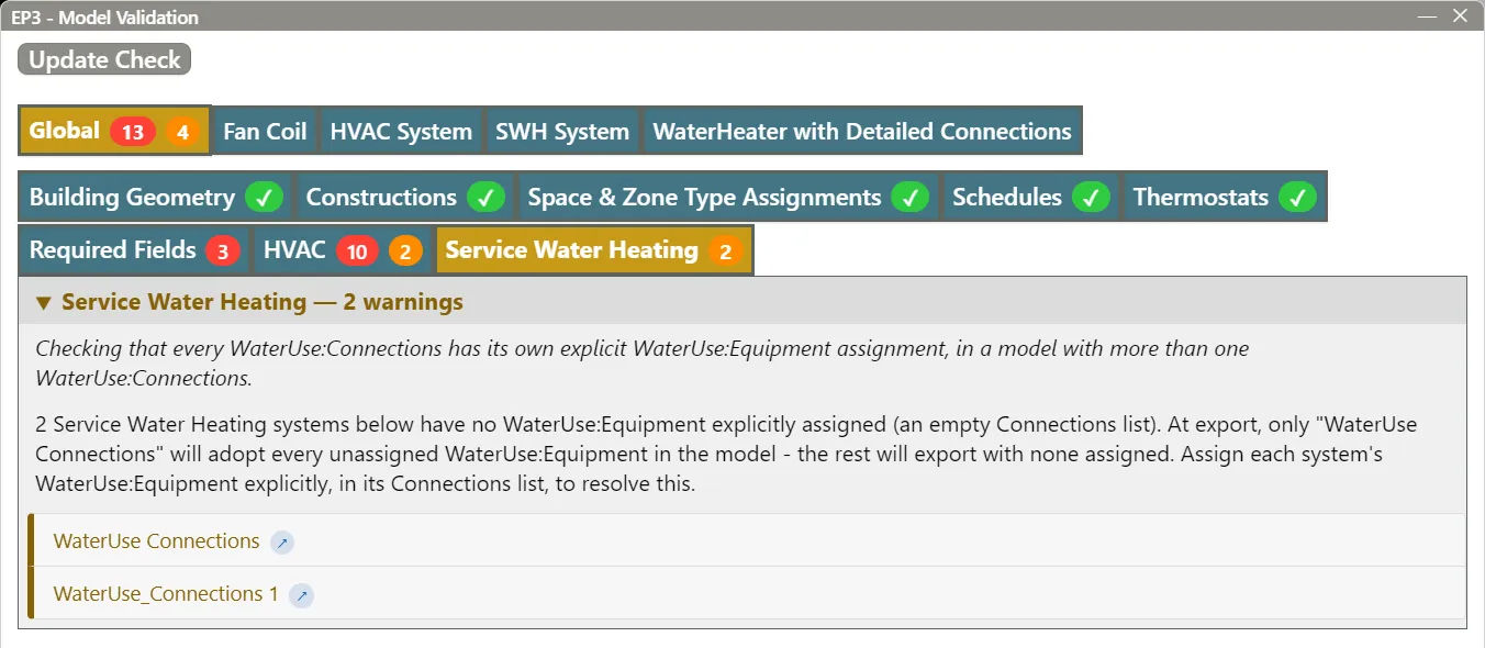
The Validate button runs these service hot water checks, on the Service Water Heating tab of the Validation dialog (Model Troubleshooting and Quality Assurance):
- WaterUse:Equipment — appears when the EEM has no
WaterUse:Equipment, with a warning that the building’s service water heating load is not being simulated. - Site:WaterMainsTemperature — a warning when the EEM has
WaterUse:Equipmentbut noSite:WaterMainsTemperature, so EnergyPlus would use a constant 10°C (50°F) mains temperature (§2.1). - Service Water Heating — appears when the EEM has two or more
WaterUse:Connectionsand at least two of them list no equipment. It names the connection that will take the unlisted equipment at export (§4.3) and lists each empty connection with a link that opens it. Listing each system’s equipment clears it. - WaterHeater:Mixed Tank Volume — a warning for each
WaterHeater:Mixedwhose Tank Volume is 0 or blank in the EEM; EnergyPlus models such a tank as an instantaneous heater.
The Required Fields tab lists a tank with no setpoint schedule, and a heat pump water heater with no compressor setpoint schedule.
When the model is exported, in the EP3 - Simulate / Export dialog or with File > Export epJSON…, a WaterUse:Connections left with no equipment because another empty connection took it is reported as an error (Running Simulations).
After a simulation, water heating energy appears under the heater’s fuel in the Water Systems end use. A water heater on the loop’s supply side that cannot hold its setpoint shows as cool water at the taps; the loop and tank temperatures are available as output variables (Viewing and Interpreting Results).
The ASHRAE 90.1 PRM generator builds the baseline’s service water heating system (ASHRAE 90.1 Performance Rating Method).
10. Where to go next
- Internal Loads, Space Types, and Zone Types — the
ZoneType’sWaterUse:Equipmentand its fields. - The Model Wizard — the Service Hot Water tab and importing templates into an existing model.
- The HVAC Outliner and Creating HVAC Systems — adding components, Draw Branch Connections, and saving templates.
- Central Plant Equipment and Plant Loops — plant loops, pumps,
Sizing:Plant, and plant setpoint managers. - Zone-Level HVAC Equipment and Zone Sizing — composites and zone assignment, for heat pump water heaters that use zone air.
- Energy Efficiency Measures (EEMs) — SWH and HVAC system alternatives and how they combine.
- Model Troubleshooting and Quality Assurance — the Validation dialog.
This handbook is also built into EP3 (Help), where its EnergyPlus links open the EnergyPlus Reference. Technical specifications · Book a demo