Fans and Fan Power
1. Overview
This chapter covers the fans in an EP3 model: which fan objects EP3 offers and where each can be placed, the inputs that set a fan’s power, what decides when a fan runs, and how to turn the fan power on an equipment schedule or in a specification into EnergyPlus inputs.
A fan’s behavior depends as much on where it sits as on its object type:
- A standalone fan on an
AirLoopHVACbranch runs when its availability schedule (or an availability manager) allows it and the loop calls for air (§3.1, §5.2). - A fan inside a composite unit, such as a fan coil, a packaged terminal unit, or an
AirLoopHVAC:UnitarySystem, is run by the unit: the unit’s Supply Air Fan Operating Mode Schedule Name decides whether it cycles with the coils or runs continuously (§3.3, §5.3).
Building the systems that hold these fans is covered in The HVAC Outliner and Creating HVAC Systems, Zone-Level HVAC Equipment and Zone Sizing, and Air Loops, Branches, and Nodes.
2. Fan types in EP3
| Object | What it models | Where EP3 offers it |
|---|---|---|
Fan:ConstantVolume |
Fixed airflow whenever it runs. | Air loop branches; the fan slot of most composite units. |
Fan:VariableVolume |
Airflow that modulates, with fan power following a fourth-order part-load polynomial (§4.2). | Air loop branches; the fan slot of the fan coil, unit heater, unit ventilator, AirLoopHVAC:UnitarySystem, and the variable-speed-fan VAV terminal. |
Fan:OnOff |
A constant-volume fan that cycles on and off with the coils it serves. | The fan slot of most composite units. It can be placed on an air loop branch, but EnergyPlus does not accept it there (§3.1). |
Fan:SystemModel |
One fan object for constant-volume, cycling, multi-speed, and variable-speed operation, with three ways to size its power (§4.3). | Air loop branches; the fan slot of every composite unit. |
Fan:ComponentModel |
A detailed model of fan, belt, motor, and drive. | Only as the exhaust fan of an AirLoopHVAC:ExhaustSystem. |
Fan:ZoneExhaust |
A fan that exhausts air from one zone. | Zone equipment (§3.4). |
The first four are in the EP3 - HVAC Components dialog (Add HVAC Component in the HVAC Outliner’s toolbar) under Air Loop Equipment, and Fan:ZoneExhaust is under ZoneHVAC (The HVAC Outliner and Creating HVAC Systems). EnergyPlus recommends Fan:SystemModel for new models; the older objects may be deprecated in a future version.
3. Where a fan sits
3.1 On an air loop’s supply branch
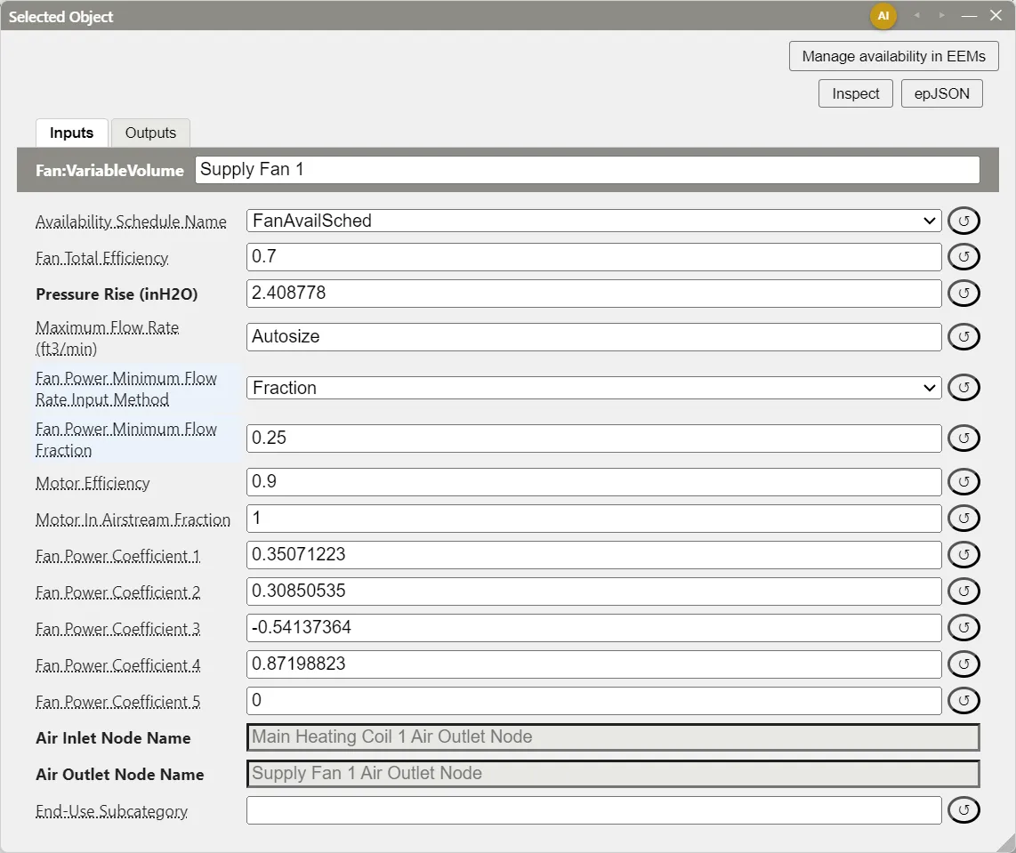
Add AirLoopHVAC builds a supply branch with an outdoor air mixer, a heating coil, a cooling coil, and a Fan:VariableVolume with a Pressure Rise of 600 Pa (2.41 in. w.c.), in that order (Air Loops, Branches, and Nodes). A fan you add from the HVAC Components dialog starts with the same 600 Pa pressure rise. Connect it to a node on the branch with Draw Branch Connections: it is inserted at that node, and the components downstream move to make room (Air Loops, Branches, and Nodes).
The fan’s position on the branch sets its arrangement:
- Draw-through: the fan follows the coils and pulls air through them. This is the default loop’s arrangement. The fan’s heat is added after the cooling coil, so the coil must leave the air colder than the supply setpoint; the default loop’s
SetpointManager:MixedAirlowers the coil outlet setpoints by the fan’s temperature rise (Air Loops, Branches, and Nodes). - Blow-through: the fan precedes the coils and pushes air through them. To build one from the default loop, select the fan and press Delete (the cooling coil and the supply outlet then meet at a shared node), and connect a new fan at the node between the mixer and the heating coil. The coil outlets are then downstream of the fan, so give them the supply air setpoint directly, for example by adding them to the loop’s
SetpointManager:Scheduled, and keepSetpointManager:MixedAiron the mixed air node. - Return fan: a second fan connected ahead of the outdoor air mixer, at the start of the branch, moves return air from the zones before it mixes with outdoor air.
A typical draw-through VAV branch with a return fan reads:
Return fan → outdoor air mixer → heating coil → cooling coil → supply fan
Choose the fan class to match the system: Fan:ConstantVolume for a constant-volume system, and Fan:VariableVolume or a continuous-speed Fan:SystemModel for a VAV system, so that fan power falls as the flow falls.
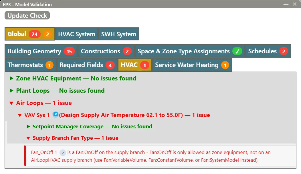
Fan:OnOff is listed with the air loop equipment, and the diagram lets you connect it to a supply branch, but EnergyPlus allows it only inside zone or unitary equipment. The Validation dialog’s Supply Branch Fan Type check fails a Fan:OnOff on an air loop’s supply branch (§7).
3.2 On the outdoor air and relief streams
Each OutdoorAir:Mixer on a loop has an Outdoor Air Stream branch and a Relief Stream branch (Air Loops, Branches, and Nodes). An outdoor air fan goes on the outdoor air stream, and a relief fan on the relief stream. Use Fan:ConstantVolume, Fan:VariableVolume, or Fan:SystemModel there: EnergyPlus’s outdoor air system does not accept Fan:OnOff.
The outdoor air mixer inside a zone unit, such as a fan coil’s, has no streams of its own, so it holds no fan.
3.3 Inside a composite unit
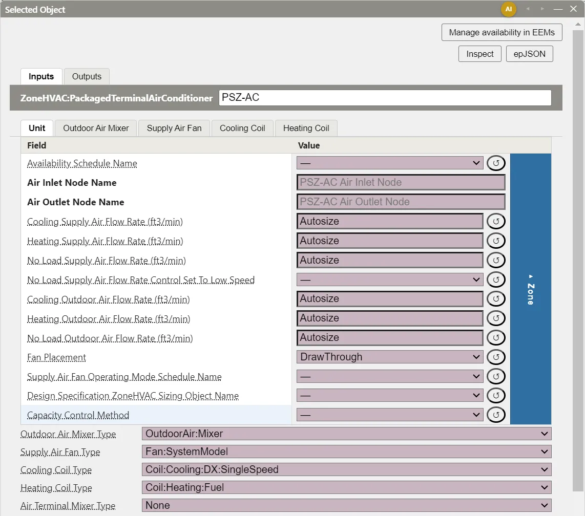
A composite unit owns its fan as a sub-component (Zone-Level HVAC Equipment and Zone Sizing). The unit’s dialog has a tab for the fan, named Supply Air Fan on most units (Fan on the powered induction units; Exhaust Air Fan, Regeneration Air Fan, or Exhaust Fan for a fan on another stream), and the Unit tab has a Type row for the fan slot, such as Supply Air Fan Type, that chooses its class (Zone-Level HVAC Equipment and Zone Sizing). The fan is named <unit name> Fan. A fan created with a composite starts with a pressure rise of 300 Pa (1.20 in. w.c.) on most units and a maximum flow of Autosize.
The Type row offers only the classes EnergyPlus accepts in that unit:
| Unit | Fan classes offered | New unit’s fan |
|---|---|---|
ZoneHVAC:FourPipeFanCoil, ZoneHVAC:UnitHeater, ZoneHVAC:UnitVentilator |
Fan:OnOff, Fan:ConstantVolume, Fan:VariableVolume, Fan:SystemModel |
Fan:OnOff (fan coil), Fan:ConstantVolume (unit heater, unit ventilator) |
AirLoopHVAC:UnitarySystem |
Fan:OnOff, Fan:ConstantVolume, Fan:VariableVolume, Fan:SystemModel, or None |
Fan:OnOff |
ZoneHVAC:PackagedTerminalAirConditioner, ZoneHVAC:PackagedTerminalHeatPump, ZoneHVAC:WindowAirConditioner, ZoneHVAC:TerminalUnit:VariableRefrigerantFlow |
Fan:OnOff, Fan:ConstantVolume, Fan:SystemModel |
Fan:OnOff |
AirLoopHVAC:TerminalUnit:VariableRefrigerantFlow |
Fan:OnOff, Fan:ConstantVolume, Fan:SystemModel, or None |
Fan:OnOff |
ZoneHVAC:WaterToAirHeatPump |
Fan:OnOff, Fan:SystemModel |
Fan:OnOff |
AirLoopHVAC:UnitaryHeatOnly, AirLoopHVAC:UnitaryHeatCool, AirLoopHVAC:Unitary:Furnace:HeatOnly, AirLoopHVAC:Unitary:Furnace:HeatCool, AirLoopHVAC:UnitaryHeatPump:AirToAir, AirLoopHVAC:UnitaryHeatPump:AirToAir:MultiSpeed |
Fan:OnOff, Fan:ConstantVolume |
Fan:OnOff |
AirLoopHVAC:UnitaryHeatPump:WaterToAir |
Fan:OnOff |
Fan:OnOff |
AirTerminal:SingleDuct:SeriesPIU:Reheat, AirTerminal:SingleDuct:ParallelPIU:Reheat |
Fan:ConstantVolume, Fan:SystemModel |
Fan:ConstantVolume |
AirTerminal:SingleDuct:VAV:Reheat:VariableSpeedFan |
Fan:SystemModel, Fan:VariableVolume |
Fan:SystemModel |
ZoneHVAC:EnergyRecoveryVentilator (supply and exhaust fans) |
Fan:OnOff, Fan:SystemModel |
Fan:OnOff |
Dehumidifier:Desiccant:System (regeneration fan) |
Fan:ConstantVolume, Fan:OnOff, Fan:SystemModel |
Fan:SystemModel |
AirLoopHVAC:ExhaustSystem |
Fan:SystemModel, Fan:ComponentModel |
Fan:SystemModel |
A heat pump water heater’s fan is covered in Service Hot Water and Solar Water Heating. The fan class is stored per EEM, so an efficiency measure can swap a unit’s fan, and switching back restores the previous fan’s inputs (Zone-Level HVAC Equipment and Zone Sizing).
Fan placement. Units whose EnergyPlus class lets the fan sit before or after the coils have a placement field on the Unit tab: Fan Placement on the packaged terminal units, the window air conditioner, the water-to-air heat pumps, and the air loop unitary systems, and Supply Air Fan Placement on the VRF terminals and the multi-speed air-to-air heat pump. BlowThrough puts the fan ahead of the coils, and DrawThrough after them; the unit’s symbol in the diagram and its exported nodes follow the choice. A new PTAC, PTHP, window air conditioner, or zone water-to-air heat pump starts at DrawThrough; a new air loop unitary system or VRF terminal starts at BlowThrough. In a draw-through PTHP or water-to-air heat pump, the fan sits between the heat pump coils and the supplemental heating coil. The fan coil, unit heater, and unit ventilator have a fixed order with the fan ahead of the coils.
3.4 Zone exhaust fans
Fan:ZoneExhaust is zone equipment: add it from the ZoneHVAC heading of the HVAC Components dialog and assign it to zones in EP3 - Select Zone Conditioning Equipment, like any zone unit (Zone-Level HVAC Equipment and Zone Sizing). EP3 writes one copy per zone. A new exhaust fan has no pressure rise: enter Pressure Rise and Maximum Flow Rate (EnergyPlus does not autosize a zone exhaust fan’s flow). Flow Fraction Schedule Name varies the flow over time, and System Availability Manager Coupling Mode (Coupled by default) ties the fan to the availability managers of the air loop serving the zone. A blank Availability Schedule Name takes the zone’s or ZoneType’s default (§5.4).
Exhausted air must be made up. When a Fan:ZoneExhaust is added while the model has no ZoneAirMassFlowConservation, the HVAC Components dialog shows a notice at its top, EP3 - Fan:ZoneExhaust Make-Up Air, with two choices. Automatically balance with infiltration (recommended) adds a model-wide ZoneAirMassFlowConservation, on in every EEM, under which EnergyPlus makes up exhausted air by raising infiltration (Adjust Zone Mixing and Return For Air Mass Flow Balance AdjustReturnOnly, Infiltration Balancing Method AddInfiltrationFlow, Infiltration Balancing Zones AllZones). EnergyPlus adjusts infiltration only in zones that have an infiltration object, so the export adds a zero-flow one for the zones that need it (Infiltration, Natural Ventilation and Airflow Networks). I’ll model this manually dismisses the notice; the fan is placed either way. The Validation dialog checks make-up air afterwards (§7), and Infiltration, Natural Ventilation and Airflow Networks covers the make-up air options in depth.
4. Fan inputs
Open a standalone fan by double-clicking it in the HVAC diagram or the HVAC Outliner; open a composite’s fan from its tab in the unit’s dialog. Pressure fields show in Pa or in. w.c. and flow fields in m³/s or cfm, following the SI/IP setting; EP3 stores SI values and converts them for display.
4.1 The core fields
Fan:ConstantVolume, Fan:VariableVolume, and Fan:OnOff share these fields:
| Field | Default | Notes |
|---|---|---|
| Availability Schedule Name | Blank (always available) | §5.1. |
| Fan Total Efficiency | 0.7 (Fan:OnOff 0.6) |
Air power delivered divided by electric power: the product of the motor and impeller efficiencies. |
| Pressure Rise | Required; EP3 enters 600 Pa for a fan added to an air loop and 300 Pa for most composite fans | Total pressure rise at full flow. |
| Maximum Flow Rate | Autosize on a composite’s fan; blank on a standalone fan | Set a standalone fan’s to Autosize or a design value. EnergyPlus reads a blank as 0, and then leaves the fan out of the simulation with a warning. |
| Motor Efficiency | 0.9 (Fan:OnOff 0.8) |
Shaft power divided by electric power. |
| Motor In Airstream Fraction | 1.0 | The share of motor losses added to the air. |
| End-Use Subcategory | General |
Groups the fan’s energy in the results’ end-use tables. |
Fan:OnOff adds two optional curves for multi-speed operation inside a parent that sets several fan speeds: Fan Power Ratio Function of Speed Ratio Curve Name and Fan Efficiency Ratio Function of Speed Ratio Curve Name. Performance Curves: Part-Load and Efficiency Behavior covers curve objects and how to edit them.
The fan’s electric power at full flow is Maximum Flow Rate × Pressure Rise ÷ Fan Total Efficiency, and that power heats the air (Air-Side System Fundamentals works the temperature rise). §6 works from this relationship.
4.2 Part-load power of Fan:VariableVolume
A Fan:VariableVolume scales its full-flow power by a part-load factor:
fpl = C1 + C2·f + C3·f² + C4·f³ + C5·f⁴
where f is the flow fraction (current flow ÷ maximum flow) and C1 to C5 are Fan Power Coefficient 1 to 5. Below the minimum set by Fan Power Minimum Flow Rate Input Method, the polynomial is evaluated at that minimum: Fraction (the default) uses Fan Power Minimum Flow Fraction (0.25 by default), and FixedFlowRate uses Fan Power Minimum Air Flow Rate. The dialog shows only the field the chosen method uses (The EP3 Interface and Model Settings). The minimum applies to the power calculation only; it does not limit the airflow.
The coefficients have no EnergyPlus defaults, and EnergyPlus reads a blank coefficient as 0: a fan whose five coefficients are all blank or zero uses no power. A Fan:VariableVolume created in EP3 (from the HVAC Components dialog, with Draw Branch Connections, by Add AirLoopHVAC, or in a composite’s fan slot) starts with the inlet vane damper coefficients below. An imported fan keeps the file’s values. To model a different fan, enter another set. EnergyPlus lists commonly used values:
| Flow control | C1 | C2 | C3 | C4 | C5 |
|---|---|---|---|---|---|
| Inlet vane dampers | 0.35071223 | 0.30850535 | −0.54137364 | 0.87198823 | 0 |
| Discharge dampers | 0.37073425 | 0.97250253 | −0.34240761 | 0 | 0 |
| Variable speed motor | 0.0015302446 | 0.0052080574 | 1.1086242 | −0.11635563 | 0 |
Worked example: VAV fan power at half flow. A Fan:VariableVolume moves a design flow of 2.0 m³/s (4,238 cfm) at a pressure rise of 600 Pa (2.41 in. w.c.) with a Fan Total Efficiency of 0.7: the default loop’s fan, sized to 2.0 m³/s. At full flow it draws
P = V̇ × ΔP ÷ η = 2.0 × 600 ÷ 0.7 = 1,714 W
In IP units, one cfm moved against one in. w.c. is 0.1176 W of air power (0.000472 m³/s × 249.1 Pa), so P = 0.1176 × 4,238 × 2.41 ÷ 0.7 = 1,714 W, or 0.40 W/cfm.
At half flow (f = 0.5, above the 0.25 minimum):
- Inlet vane dampers: fpl = 0.35071 + 0.30851(0.5) − 0.54137(0.25) + 0.87199(0.125) = 0.479, so P = 0.479 × 1,714 = 820 W.
- Variable speed motor: fpl = 0.00153 + 0.00521(0.5) + 1.10862(0.25) − 0.11636(0.125) = 0.267, so P = 0.267 × 1,714 = 457 W.
At the same flow, the variable speed drive uses 44% less power than the inlet vanes, so in a VAV model the coefficients matter as much as the design power.
4.3 Fan:SystemModel: power sizing and speed control
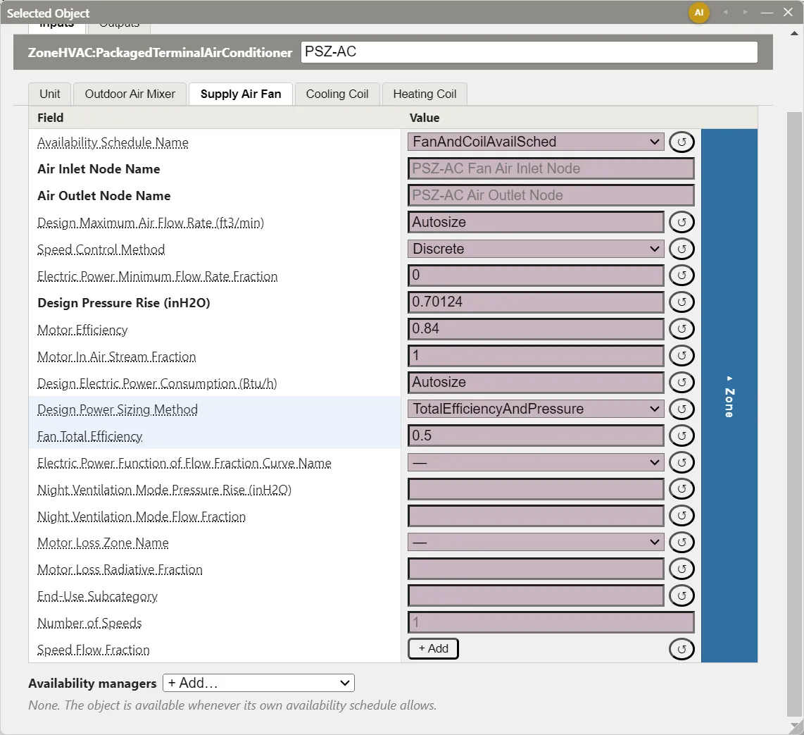
Fan:SystemModel takes a Design Maximum Air Flow Rate (Autosize by default), a Design Pressure Rise (required), and a Design Electric Power Consumption (Autosize by default). An autosized design power is calculated by Design Power Sizing Method, and the dialog shows only the input that method uses:
| Design Power Sizing Method | Field shown | Design power |
|---|---|---|
PowerPerFlowPerPressure (the default) |
Electric Power Per Unit Flow Rate Per Unit Pressure, 1.66667 W/((m³/s)·Pa) by default | flow × pressure rise × the value |
PowerPerFlow |
Electric Power Per Unit Flow Rate, in W/(m³/s) or W/cfm | flow × the value |
TotalEfficiencyAndPressure |
Fan Total Efficiency, 0.7 by default | flow × pressure rise ÷ the efficiency |
The default 1.66667 W/((m³/s)·Pa) is equivalent to a total efficiency of 1 ÷ 1.66667 = 0.60. Electric Power Per Unit Flow Rate Per Unit Pressure has no IP conversion and is entered in SI in both unit systems. With PowerPerFlow, the pressure rise does not affect the power, but EnergyPlus still uses it for the heat the fan adds to the air.
Speed Control Method is Discrete by default. A constant-volume or cycling fan uses Discrete with one speed; a VAV fan uses Continuous, which requires an Electric Power Function of Flow Fraction Curve Name, a curve of power fraction against flow fraction (Performance Curves: Part-Load and Efficiency Behavior). A Curve:Quartic with the coefficients of §4.2 reproduces a Fan:VariableVolume. For a multi-speed fan, enter one row per speed in the Speed Flow Fraction table (a flow fraction and an electric power fraction, in increasing order); Number of Speeds is read-only and counts the rows. Electric Power Minimum Flow Rate Fraction (0.2 by default) sets the lowest flow fraction used for power under Continuous control.
4.4 Values that differ by zone or replicate, and simplified view
A composite’s fan is copied for each zone the unit serves, and an air loop’s fan for each replicate of the loop. A value that should differ for one copy, such as one zone’s fan flow or one floor’s pressure rise, goes in that zone’s or replicate’s column of the blue drawer bar on the fan’s tab (Zone-Level HVAC Equipment and Zone Sizing, Air Loops, Branches, and Nodes).
Simplified view shows a fan’s flow, pressure rise, efficiencies, and end-use subcategory, plus Fan:VariableVolume’s minimum flow fraction and Fan:SystemModel’s design power sizing method. The availability schedule, the part-load coefficients, the speed table, and the curves appear in complex view (The EP3 Interface and Model Settings).
5. When a fan runs
5.1 Availability Schedule Name
Every fan has an Availability Schedule Name. While its value is 0 the fan is off, whatever the thermostat, the loop, or the parent unit asks for; a blank field means always available. An availability manager can override it, turning the fan on or off (Controllers and Availability Managers).
Coils, composite units, and most other equipment have an availability schedule too, and the same rule applies to each. An occupancy schedule placed in an availability field turns the equipment fully off in unoccupied hours: no heating, no cooling, and no ventilation, even when the zone drifts far past its setback setpoints. Unmet hours outside occupied periods often trace back to this. Use an availability schedule for periods when the equipment cannot run (a seasonal shutdown, equipment not yet installed), leave it blank or Always On otherwise, and set occupied-hours behavior with the mechanisms in §5.2 and §5.3.
5.2 Air loop fans: availability managers and Night Cycle Control
A standalone fan on an air loop has no operating mode field. It runs when its availability schedule allows and the loop has air to move; a VAV fan’s flow follows its terminals. The usual pattern for an air handler is an availability schedule that is on in occupied hours and off at night, plus a night cycle that brings the fans back on when a zone drifts past its setback setpoint:
- Night Cycle Control
Yes, in the loop’s dialog, gives the loop anAvailabilityManager:NightCyclewhose fan schedule is always the availability schedule of the loop’s supply fan, the first fan on the supply branch (Air Loops, Branches, and Nodes). - A fan’s Availability Schedule Name can be Follow ZoneHVAC Fan Operating Mode Schedules, which runs the loop whenever any zone it serves has its supply air fan operating mode schedule on; the loop’s night cycle and optimum start use the supply fan’s schedule as their Fan Schedule Name automatically (Controllers and Availability Managers).
- Other availability managers, such as
AvailabilityManager:OptimumStart, go in the loop’s Availability managers list (Air Loops, Branches, and Nodes, Controllers and Availability Managers).
5.3 Zone equipment: Supply Air Fan Operating Mode Schedule
A composite zone unit controls its fan through its Supply Air Fan Operating Mode Schedule Name, on the Unit tab:
- A value of 0 cycles the fan with the coils: it runs only while the unit heats or cools.
- A value above 0 (usually 1) runs the fan continuously while the unit is available, and the coils cycle. Outdoor air the unit supplies is delivered throughout those hours.
- Left blank, the fan cycles on most zone units. Set the schedule explicitly when continuous operation is intended.
A schedule of 1 in occupied hours and 0 otherwise gives continuous fan operation, and continuous ventilation, while occupied, and cycling operation at night. A unit that supplies no outdoor air, such as a unit heater, can cycle at all hours, which saves fan energy.
The schedule interacts with the fan class and the unit’s controls:
Fan:ConstantVolumeworks only with continuous operation (schedule values never 0). With a schedule that cycles, useFan:OnOfforFan:SystemModel.- On
ZoneHVAC:FourPipeFanCoil, EnergyPlus uses the schedule only with theMultiSpeedFanCapacity Control Method; the other methods set fan operation themselves. The EP3 Library’s Fan Coil system usesMultiSpeedFan. - A unit whose fan modulates its flow while running continuously, such as a fan coil with a variable-flow capacity control method, delivers less than its design outdoor air at part load. Check that the outdoor air delivered at those flows meets the requirement.
5.4 Defaults from the Zone and ZoneType
A zone unit’s availability schedule and fan operating mode schedule can be left blank and filled per zone. When the equipment leaves Availability Schedule Name (a VRF terminal’s Terminal Unit Availability Schedule) or Supply Air Fan Operating Mode Schedule Name blank, each zone’s copy takes the value from its Zone, and if the Zone has none, from its ZoneType:
- The
ZoneType’s Zone Properties tab has ZoneHVAC Availability Schedule Name and ZoneHVAC Supply Air Fan Operating Mode Schedule Name. - The
Zone’s dialog has ZoneHVAC Availability Schedule Name and Zone Supply Air Fan Operating Mode Schedule, for a zone that departs from itsZoneType. - A value on the equipment, shared or in one zone’s column, always wins.
The fan operating mode default also fills a four-pipe fan coil’s Outdoor Air Schedule Name. The defaults apply to ZoneHVAC:* units, AirTerminal:* terminals, and Fan:ZoneExhaust; they do not reach fans on an air loop or the unitary systems on its branch. Set the schedules once per ZoneType when a group of zones runs on the same hours, and keep per-zone or per-unit values for exceptions. In the unit’s Zone columns, each blank field shows the schedule that zone’s copy inherits, on the rose inherited background. Internal Loads, Space Types, and Zone Types lists the ZoneType fields, and Zone-Level HVAC Equipment and Zone Sizing shows them in a unit’s dialog.
5.5 Unitary systems on an air loop
An AirLoopHVAC:Unitary* system on a supply branch also has a Supply Air Fan Operating Mode Schedule Name, with the same meaning for 0 and values above 0, and it is not filled from the ZoneType. EnergyPlus restricts it by fan class and control type:
- With
Fan:ConstantVolume, or withFan:VariableVolumein anAirLoopHVAC:UnitarySystem, the fan must run continuously: use a schedule whose values are all above 0, such as a constant 1. A schedule with zeros stops the simulation with a severe error. - An
AirLoopHVAC:UnitarySystemwith Control TypeSetPointalso needs values above 0; with the field blank, its fan runs continuously. WithLoadcontrol and the field blank, EnergyPlus requiresFan:OnOfforFan:SystemModel.
For a VAV unitary system, set the operating mode schedule to a constant 1, and control when the system runs with the fan’s availability schedule and Night Cycle Control (§5.2). The EP3 Library’s packaged VAV systems use SetPoint control with the field blank, so their fans run continuously whenever they are available.
6. Translating fan power data into EP3 inputs
6.1 The relationship
The simple fan objects relate electric power to airflow and pressure rise through one efficiency:
Electric power [W] = Airflow [m³/s] × Pressure rise [Pa] ÷ Fan Total Efficiency
EP3 converts IP entries to SI, so units need no hand conversion. The quantity does: specifications and energy standards often give fan power as a power density (W/cfm or W/(L/s)), and submittals give brake horsepower and static pressure, while Fan:ConstantVolume, Fan:VariableVolume, and Fan:OnOff take a pressure rise and an efficiency. The examples below convert each. The airflow cancels, so the result holds at whatever flow the fan is sized to.
For reference, the fans EP3 creates come out at:
| Fan | Pressure rise | Efficiency | Power density |
|---|---|---|---|
Fan:VariableVolume or Fan:ConstantVolume added to an air loop |
600 Pa (2.41 in. w.c.) | 0.7 | 857 W/(m³/s) = 0.40 W/cfm |
Fan:OnOff in a new composite |
300 Pa (1.20 in. w.c.) | 0.6 | 500 W/(m³/s) = 0.24 W/cfm |
The EP3 Library’s PSZ-AC fan (Fan:SystemModel, TotalEfficiencyAndPressure) |
174.7 Pa (0.70 in. w.c.) | 0.5 | 349 W/(m³/s) = 0.16 W/cfm |
(1 W/(m³/s) = 0.000472 W/cfm.) These are starting values; review them against the design.
6.2 From a power allowance in W/cfm (IP)
A specification sets a fan power allowance of 0.75 W/cfm, and the selected fan is expected to reach a Fan Total Efficiency of 0.65.
The IP fan law gives air horsepower from flow and pressure:
Air power [hp] = Airflow [cfm] × Pressure [in. w.c.] ÷ 6,356
The constant converts cfm × in. w.c. to ft·lbf/min and then to horsepower: 1 in. w.c. = 5.192 lbf/ft², and 1 hp = 33,000 ft·lbf/min, so 33,000 ÷ 5.192 = 6,356. With 1 hp = 745.7 W, the electric power is
Electric power [W] = Airflow × Pressure × 745.7 ÷ (6,356 × Fan Total Efficiency)
Setting the electric power equal to the allowance × airflow cancels the airflow:
Pressure [in. w.c.] = Allowance [W/cfm] × 6,356 × Fan Total Efficiency ÷ 745.7
Pressure = 0.75 × 6,356 × 0.65 ÷ 745.7 = 3,099 ÷ 745.7 = 4.16 in. w.c.
Enter Pressure Rise = 4.16 in. w.c. and Fan Total Efficiency = 0.65, and the fan reproduces 0.75 W/cfm at any design flow. For a 2,000 cfm fan, that is 0.75 × 2,000 = 1,500 W.
6.3 The same allowance in SI
With 1 cfm = 0.00047195 m³/s, the allowance is
0.75 W/cfm ÷ 0.00047195 m³/s per cfm = 1,589 W/(m³/s) (1.59 W/(L/s))
In SI the airflow cancels with no unit constant:
Pressure rise [Pa] = Power density [W/(m³/s)] × Fan Total Efficiency = 1,589 × 0.65 = 1,033 Pa
Converted back, 1,033 Pa ÷ 249.09 Pa per in. w.c. = 4.15 in. w.c. The 0.01 in. difference from §6.2 comes from the rounded 6,356 constant, which takes 1 in. w.c. as 248.6 Pa. Check at 2,000 cfm (0.9439 m³/s): 0.9439 × 1,033 ÷ 0.65 = 1,500 W, matching.
6.4 From a submittal’s brake horsepower and static pressure
| Submittal value | IP | SI |
|---|---|---|
| Design airflow | 2,000 cfm | 0.9439 m³/s |
| Total static pressure | 3.5 in. w.c. | 871.8 Pa |
| Fan brake horsepower | 1.35 hp | 1,006.7 W |
| Motor efficiency | 0.87 | 0.87 |
- Pressure Rise is the total static pressure: 3.5 in. w.c. × 249.09 = 872 Pa.
- Electric power is shaft power divided by motor efficiency: 1.35 hp × 745.7 W/hp ÷ 0.87 = 1,006.7 ÷ 0.87 = 1,157 W.
- Solve the relationship for the efficiency: Fan Total Efficiency = 872 Pa × 0.9439 m³/s ÷ 1,157 W = 823 ÷ 1,157 = 0.71.
- Enter Motor Efficiency = 0.87. It does not change the fan’s power; it sets how much of the motor’s loss reaches the air when Motor In Airstream Fraction is below 1.
Check in IP units: air horsepower is 2,000 × 3.5 ÷ 6,356 = 1.10 hp, so the impeller efficiency is 1.10 ÷ 1.35 = 0.82, and 0.82 × 0.87 = 0.71, matching step 3.
6.5 Entering the result in Fan:SystemModel
The same fan goes into Fan:SystemModel by any of its sizing methods (§4.3), with Design Pressure Rise = 872 Pa (3.5 in. w.c.) in each case:
TotalEfficiencyAndPressure: Fan Total Efficiency = 0.71.PowerPerFlowPerPressure: Electric Power Per Unit Flow Rate Per Unit Pressure = 1 ÷ 0.711 = 1.41 W/((m³/s)·Pa).PowerPerFlow: Electric Power Per Unit Flow Rate = 1,157 W ÷ 0.9439 m³/s = 1,226 W/(m³/s); in IP mode, enter 1,157 ÷ 2,000 = 0.579 W/cfm.
Each gives 1,157 W at the 2,000 cfm design flow. PowerPerFlow is the direct route from a W/cfm allowance: enter the allowance itself.
6.6 Checking the inputs
A derived Fan Total Efficiency between about 0.5 and 0.8 is typical of a well-selected fan and motor. A value near or above 0.9, or below 0.3, usually means that the pressure, the horsepower, and the flow were taken from different operating points. All three should describe one operating point before they go into the model.
Energy codes and rating methods set their own fan power limits. The ASHRAE 90.1 PRM generator applies the Appendix G limits to the baseline (ASHRAE 90.1 Performance Rating Method).
7. Checking fans
The Validation dialog (Validate in the top toolbar) checks fans in its HVAC section (Model Troubleshooting and Quality Assurance):
- Supply Branch Fan Type, in each air loop’s card, fails each
Fan:OnOffon the loop’s supply branch: “Fan:OnOff is only allowed as zone equipment, not on an AirLoopHVAC supply branch (use Fan:VariableVolume, Fan:ConstantVolume, or Fan:SystemModel instead).” The check appears only on a loop that has one. - Setpoint Manager Coverage shows, for a
SetpointManager:MixedAir, the fan whose temperature rise it subtracts, and fails one whose fan inlet and outlet nodes belong to two different fans or to none (Air Loops, Branches, and Nodes). - Fan:VariableVolume Power Coefficients fails each
Fan:VariableVolumewhose Fan Power Coefficient 1 to 5 are all blank in the checked EEM, since EnergyPlus then calculates zero fan power at every flow. A coefficient of 0 counts as entered. The check appears only when a fan fails it, usually an imported fan or one whose coefficients were cleared (§4.2). - Exhaust Fan Make-Up Air appears when the model has a
Fan:ZoneExhaust. It fails when the model has noZoneAirMassFlowConservation, with a Fix This button, and warns when one exists but does not balance every zone with infiltration, with a Switch to Automatic Infiltration Backstop button. Both buttons apply the settings of Automatically balance with infiltration (recommended) (§3.4) (Model Troubleshooting and Quality Assurance).
After a run, each fan reports Fan Electricity Rate and Fan Electricity Energy, and the sized flows and powers appear in the Component Sizing Summary (Viewing and Interpreting Results). A fan that reports no energy while its loop runs usually has blank Fan:VariableVolume coefficients or a blank maximum flow rate (§4.1, §4.2).
8. Where to Look Next
- The HVAC Outliner and Creating HVAC Systems — adding components and drawing branch connections.
- Zone-Level HVAC Equipment and Zone Sizing — composite units, their sub-component tabs, zone columns, and Zone and ZoneType defaults.
- Air Loops, Branches, and Nodes — the supply branch, outdoor air streams,
SetpointManager:MixedAir, Night Cycle Control, and replicates. - Performance Curves: Part-Load and Efficiency Behavior — the curves behind
Fan:SystemModeland multi-speedFan:OnOff. - Controllers and Availability Managers — each availability manager type and how its status overrides a fan’s schedule.
- Infiltration, Natural Ventilation and Airflow Networks — make-up air for zone exhaust fans.
- Model Troubleshooting and Quality Assurance — the Validation dialog and diagnosing unmet hours.
This handbook is also built into EP3 (Help), where its EnergyPlus links open the EnergyPlus Reference. Technical specifications · Book a demo