Zone-Level HVAC Equipment and Zone Sizing
1. Overview
Zone equipment conditions one zone at a time: a fan coil, a packaged terminal air conditioner, a baseboard, an ideal loads system, an exhaust fan. This chapter covers how such equipment is built in EP3, how it is assigned to zones, and how Sizing:Zone sets the design loads and airflows the equipment autosizes to:
- the zone equipment types EP3 offers, and the difference between composite units and plain objects (§2);
- adding and editing equipment, including values that differ by zone and the defaults a zone’s
ZoneTypesupplies (§3, §4); - the EP3 - Select Zone Conditioning Equipment dialog, which decides which equipment serves each zone, in what order, and how the load is shared (§5);
Sizing:Zoneand its fields, with a worked airflow example (§6);- zone multipliers, and the checks that catch zone-level problems (§7, §8).
Air terminals (VAV and constant-volume boxes, powered induction units) are zone equipment too, and are assigned to zones with the same dialog, but they sit on an air loop’s demand side; Air Loops, Branches, and Nodes covers them. Choosing between zone equipment and an air loop system is covered in The HVAC Outliner and Creating HVAC Systems.
2. Zone equipment in EP3
2.1 One object, one copy per zone
A piece of zone equipment is one object in the model, drawn once in the HVAC diagram and listed once in the HVAC Outliner’s ZoneHVAC section, however many zones it serves. The Fan Coil template assigned to ten zones is one ZoneHVAC:FourPipeFanCoil named Fan Coil.
At export, EP3 writes one copy of the object for each zone that uses it. When the object serves more than one zone, each copy is named with its zone in front of the object’s name (<zone> Fan Coil), and its sub-components and nodes follow the same pattern (<zone> Fan Coil CC). Equipment that serves one zone keeps its name; ZoneHVAC:IdealLoadsAirSystem always takes the zone prefix. Each zone also gets the ZoneHVAC:EquipmentList and ZoneHVAC:EquipmentConnections EnergyPlus requires, built from the zone’s assignment (§5).
The copies reach the plant the same way. A fan coil’s cooling coil is connected once, to one demand branch of the chilled water loop; at export that branch becomes one parallel branch per zone, each holding that zone’s copy of the coil. A component replicated this way must be alone on its branch.
Because every copy starts from the same object, a change to the object changes every zone’s unit. A value that should differ for one zone is entered in that zone’s column (§4.2); a second object is not needed.
2.2 Composite units
Most packaged and fan-driven zone units are composites: a parent object (the EnergyPlus class itself, such as ZoneHVAC:PackagedTerminalAirConditioner) that owns its sub-components, such as an outdoor air mixer, a supply fan, and one or more coils. Each sub-component fills a slot. The parent’s dialog chooses which class fills each slot, from the classes EnergyPlus accepts there (§4.1), and EP3 wires the nodes between them. Sub-components are drawn inside the unit’s symbol and edited from its dialog; they have no outliner rows.
Two composites can hold the same coil and fan classes and behave differently, because the parent’s controls (capacity control method, fan operating mode, outdoor air control) decide how the package runs. The Input Output Reference documents each parent’s fields.
2.3 Plain zone objects
Baseboards, low-temperature radiant systems, the ideal loads system, and Fan:ZoneExhaust are plain objects: one object with its fields and no sub-components. A water baseboard or a hydronic radiant system connects to a plant loop by its water nodes.
Radiant objects have an EP3 field, Radiant Surface Source: Floor (the default), Ceiling (ceilings and roofs), All Surfaces, or Custom. For the first three, EP3 builds the surface list at export from each zone’s surfaces, each surface’s fraction being its share of the area, so the list follows the geometry as it changes. Custom uses a surface list you enter. A low-temperature radiant system can use only surfaces whose construction has an internal heat source.
2.4 The zone equipment types
| Type | Kind | Capacity comes from |
|---|---|---|
ZoneHVAC:FourPipeFanCoil |
Composite: outdoor air mixer, supply fan, water cooling coil, water or electric heating coil, optional air terminal mixer | Chilled and hot water loops; an electric heating coil needs no hot water loop |
ZoneHVAC:PackagedTerminalAirConditioner |
Composite: outdoor air mixer, fan, DX cooling coil, fuel, electric, water, or steam heating coil, optional air terminal mixer | Self-contained DX cooling; a water or steam heating coil needs a plant loop |
ZoneHVAC:PackagedTerminalHeatPump |
Composite: as the PTAC, with a DX heating coil and a supplemental heating coil | Self-contained; a water or steam supplemental coil needs a plant loop |
ZoneHVAC:WaterToAirHeatPump |
Composite: as the PTHP, with water-to-air coils | A condenser, cooling, or heating water loop |
ZoneHVAC:WindowAirConditioner |
Composite: outdoor air mixer, fan, DX cooling coil | Self-contained; cooling only |
ZoneHVAC:TerminalUnit:VariableRefrigerantFlow |
Composite: optional outdoor air mixer, fan, VRF cooling and heating coils, optional supplemental heating coil | A VRF outdoor unit, connected with the unit’s Assign to VRF outdoor units… button (The HVAC Outliner and Creating HVAC Systems) |
ZoneHVAC:UnitHeater |
Composite: fan, heating coil | A fuel or electric coil, or a hot water or steam loop |
ZoneHVAC:UnitVentilator |
Composite: fan, optional cooling and heating coils, optional air terminal mixer, with a built-in outdoor air mixer | Water coils on plant loops, or fuel or electric heating |
ZoneHVAC:EnergyRecoveryVentilator |
Composite: heat exchanger, supply fan, exhaust fan, optional controller | Ventilation only (Outdoor Air, Ventilation, and Energy Recovery) |
AirLoopHVAC:ExhaustSystem |
Composite: central exhaust fan and a ZoneHVAC:ExhaustControl |
Exhaust only; assigned to zones like zone equipment, but not listed in their equipment lists |
ZoneHVAC:Baseboard:Convective:Water, ZoneHVAC:Baseboard:RadiantConvective:Water |
Plain | A hot water loop |
ZoneHVAC:Baseboard:Convective:Electric, ZoneHVAC:Baseboard:RadiantConvective:Electric |
Plain | Electric resistance |
ZoneHVAC:LowTemperatureRadiant:VariableFlow, ZoneHVAC:LowTemperatureRadiant:ConstantFlow |
Plain | Hot and chilled water loops |
ZoneHVAC:LowTemperatureRadiant:Electric |
Plain | Electric resistance |
ZoneHVAC:IdealLoadsAirSystem |
Plain | None: EnergyPlus supplies whatever heating and cooling the zone needs |
Fan:ZoneExhaust |
Plain | Exhaust only (Infiltration, Natural Ventilation, and Airflow Networks) |
Central Plant Equipment and Plant Loops covers the loops the plant-connected types draw from. A heat pump water heater that takes its air from the zone is also zone equipment, and appears in the assignment dialog while it is configured that way (Service Hot Water and Solar Water Heating).
ZoneHVAC:IdealLoadsAirSystem has no fan or coil. EnergyPlus supplies the airflow, temperature, and (optionally) humidity needed to hold the zone at its setpoints, with outdoor air, economizer, and heat recovery available as fields on the object. It gives a runnable model before any system is designed, which makes it useful for comparing envelope and load decisions alone. It needs a thermostat and a Sizing:Zone like any other zone equipment.
3. Adding zone equipment
Most zone equipment arrives with an HVAC system template, from the Model Wizard’s HVAC Systems tab or the Import dialog’s Library templates tab, and the Wizard assigns each system’s zone equipment to the ZoneTypes it imported (The Model Wizard).
To add one piece of equipment, click Add HVAC Component in the HVAC Outliner’s toolbar. The EP3 - HVAC Components dialog lists the types that can be added, by category; the ZoneHVAC category holds the equipment of §2.4 and the air terminals. Click a type to place it in the HVAC diagram. A composite is placed with a default class in each required slot, its sub-components named after the unit (<unit> Fan, <unit> CC, <unit> HC). A new DX coil gets EnergyPlus’s example performance curves, with its rated capacity and flow set to Autosize.
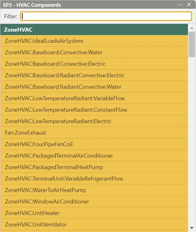
New equipment serves no zone until it is assigned (§5). Equipment with a water side must also be connected to a plant loop’s demand side with Draw Branch Connections (The HVAC Outliner and Creating HVAC Systems); until it is, the export warns that its water side is not on a branch.
4. Editing zone equipment
Double-click a unit in the HVAC Outliner or the HVAC diagram to open it in the Selected Object dialog. Its epJSON button works as for any object (The EP3 Interface and Model Settings); for zone equipment, epJSON shows every zone’s copy in the active EEM. The Outputs tab has a sub-tab for the unit and one for each sub-component with variables, such as its fan and coils.
4.1 The Unit tab and sub-component tabs
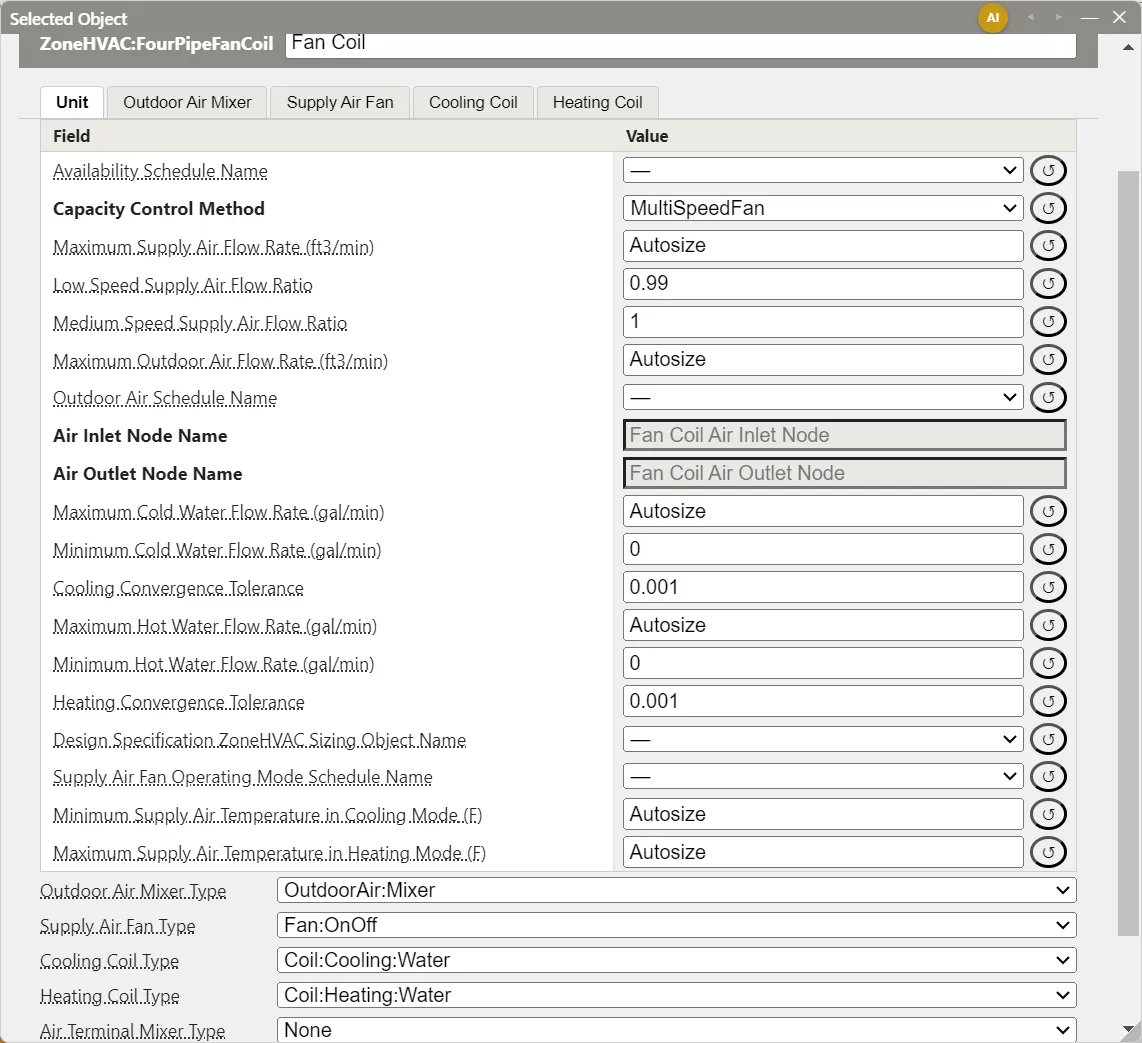
A composite’s dialog has a Unit tab, then one tab per sub-component present in the active EEM, in airflow order: for a fan coil, Outdoor Air Mixer, Supply Air Fan, Cooling Coil, and Heating Coil.
The Unit tab holds the parent’s fields and, below them, one Type row per slot: Outdoor Air Mixer Type, Supply Air Fan Type, Cooling Coil Type, Heating Coil Type, and Air Terminal Mixer Type on a fan coil. The Type row chooses the sub-component’s class, and sets an optional slot to None. EP3 fills in the parent’s fields that name its sub-components and nodes, so they are not shown as rows.
Type rows are stored per EEM, so an EEM can swap a fan or a coil: a fan coil can run a Fan:OnOff in the base model and a Fan:SystemModel in an efficiency measure. Switching a slot’s class keeps the previous sub-component and its inputs, so switching back restores them. Where one sub-component rules out another, the Type row stays and its tooltip says the sub-component is not used: a fan coil with an air terminal mixer has no outdoor air mixer, because its outdoor air arrives from an air loop through the terminal mixer.
Where a field chooses a calculation method, the dialog shows only the fields that method uses (The EP3 Interface and Model Settings). On zone equipment this applies to the baseboards’ and electric radiant systems’ Heating Design Capacity Method, and to the PTAC’s and PTHP’s supply air temperature limits, which appear only for the SingleZoneVAV capacity control method. On a ZoneHVAC:LowTemperatureRadiant:VariableFlow unit, the heating or cooling capacity and flow fields of a water side that is not connected to a loop in the active EEM are shown greyed, with the note “Heating side not connected: not exported” (or Cooling); their values are kept and return to normal once the side is connected.
4.2 Values for one zone
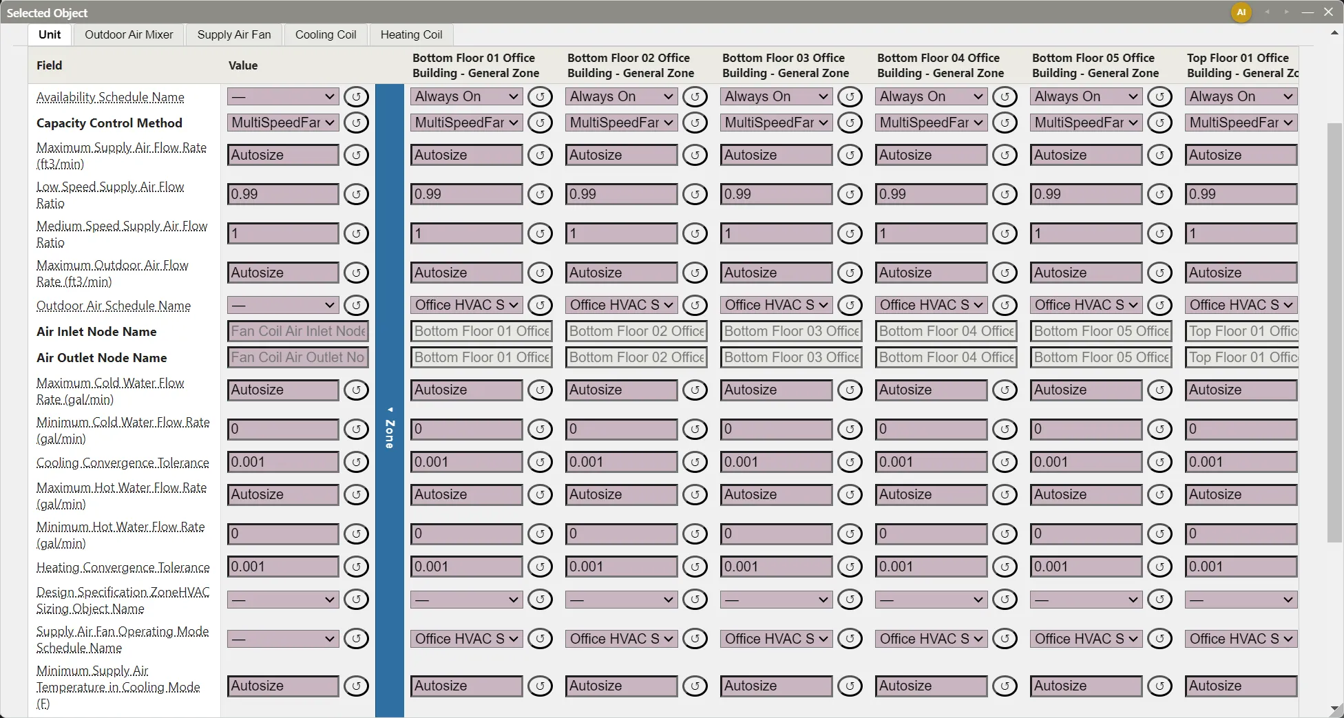
Each table in a zone unit’s dialog, on the Unit tab and every sub-component tab, has a blue Zone bar along its right edge. Click it to open one column per zone the unit serves, beside the shared Value column:
- The shared value applies to every zone’s copy.
- A value entered in a zone’s column applies to that zone’s copy and overrides the shared value. ↺ clears it.
- Node rows show each zone’s copy name and cannot be edited.
- Yes/No fields and the Type rows have no zone columns; they are shared.
A zone column is the way to give one copy a different capacity, schedule, or coil input. Like every field, these values can differ by EEM.
4.3 Defaults from the Zone and ZoneType
Four equipment fields can be left blank and filled per zone: Availability Schedule Name, Supply Air Fan Operating Mode Schedule Name, Design Specification Outdoor Air Object Name, and Design Specification ZoneHVAC Sizing Object Name. A VRF terminal’s Terminal Unit Availability Schedule and a fan coil’s Outdoor Air Schedule Name take part too. When the equipment leaves one of these fields blank, each zone’s copy takes the zone’s value, and if the zone has none, its ZoneType’s. A value on the equipment, shared or for one zone, always wins. This applies to every ZoneHVAC:* object, every AirTerminal:*, and Fan:ZoneExhaust. Of a composite’s sub-components, only an AirTerminal:SingleDuct:Mixer takes a default, its Design Specification Outdoor Air Object Name, shown in the Zone columns of its tab. Internal Loads, Space Types, and Zone Types lists the ZoneType fields and which equipment fields each fills.
In the Zone columns, a blank field shows the value that zone’s copy inherits, on the rose inherited background. The shared Value column shows only the equipment’s value, since the defaults belong to the zones. In the fancoil_office sample, the Office Building - General ZoneType sets the availability schedule to Always On and the fan operating mode schedule to Office HVAC System, so every zone’s Fan Coil copy inherits both, and its Outdoor Air Schedule Name follows the fan operating mode schedule.
An air loop whose fans are set to Follow ZoneHVAC Fan Operating Mode Schedules reads the fan operating mode schedule of each zone it serves with the ZoneType first, because air terminals have no such field (Controllers and Availability Managers).
4.4 Availability managers
A composite unit whose EnergyPlus class takes an availability manager list shows an Availability managers panel below its tabs. Their statuses combine by precedence, whatever their order: any ForceOff wins, otherwise any CycleOn. EP3 writes the AvailabilityManagerAssignmentList at export. Controllers and Availability Managers covers how statuses combine and the manager types.
5. Assigning equipment to zones
5.1 The Select Zone Conditioning Equipment dialog
Click View Zone HVAC Assignments in the HVAC Outliner’s toolbar to open EP3 - Select Zone Conditioning Equipment. It has two tabs with the same row editor:
- Assign HVAC Systems by Template — one row per
Sizing:Zoneobject. In a template model that is one row perZoneType, with the number of zones it covers. The equipment on a row is the default for every zone itsSizing:Zonecovers. - Assign HVAC Systems by Zone — one row per zone, for a zone whose equipment should differ from its template’s. Each row also reports the zone’s thermostat (§5.5).
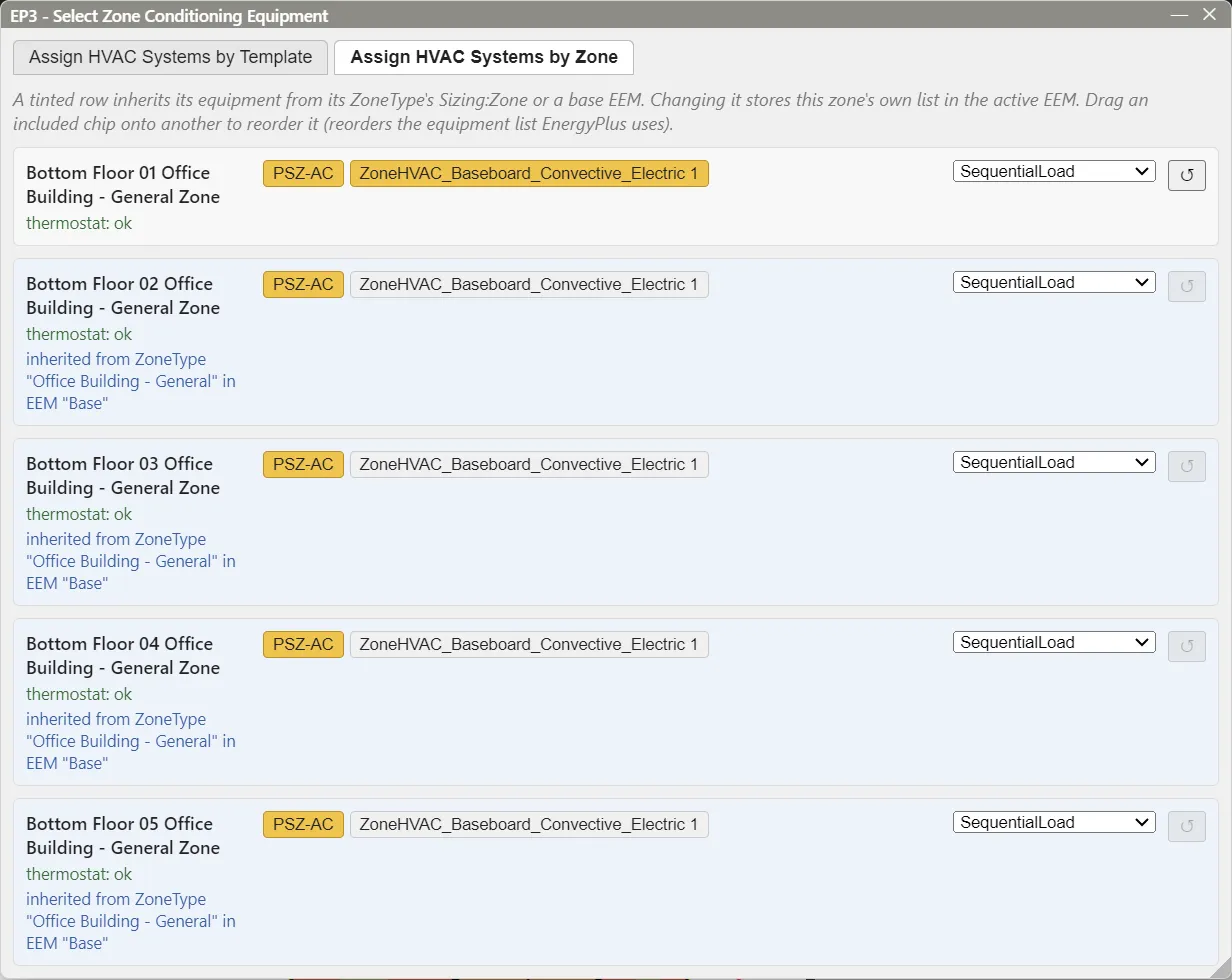
Each row shows every piece of zone equipment that is on in the active EEM as a chip. A gold chip is included and a grey chip is not; click a chip to switch it. A newly included chip goes to the end of the row’s order. The dialog assigns equipment that already exists: add the equipment first (§3), then assign it here.
5.2 Inherited rows
A zone with no list stored for it uses its template’s. On the by-Zone tab such a row is tinted, and a note under the zone’s name names the ZoneType or Sizing:Zone it inherits from, and the EEM when the list is stored in another one. Changing anything on a tinted row stores a list for that zone, which then wins over the template’s. The row’s ↺ button drops what the row stores in the active EEM, so it inherits again.
Rows are also inherited through the EEMs. A change is stored in the active EEM only, and an EEM with no list stored for a row uses its parent EEM’s; such a row is tinted too, with a note naming the EEM. A zone’s equipment comes from the first of these that has a list, each searched through the active EEM and its parents: the zone, then a Sizing:Zone pointed at the zone or a plain ZoneList, then its ZoneType’s Sizing:Zone.
A zone switched off in the active EEM shows “zone excluded from this EEM: no equipment can be assigned”, and its row cannot be edited.
5.3 Equipment order
When a zone has more than one piece of equipment, the order of its gold chips is the order of its ZoneHVAC:EquipmentList. To move an included chip, press it and release the pointer over another included chip in the same row; it takes that chip’s position. EP3 writes this order as both the cooling sequence and the heating or no-load sequence.
Under the default load distribution, EnergyPlus calls on the first piece of equipment to meet the zone’s load, then passes whatever it did not meet to the next. Order equipment from least controllable to most controllable: equipment with a fixed or limited output first, and the equipment best able to modulate last, so it meets the remainder. A dedicated outdoor air system’s terminal serving a zone with a fan coil is the usual case. The terminal delivers a roughly fixed flow of tempered outdoor air, which can add to the zone’s load as easily as reduce it. Listed first, its contribution is applied and the fan coil meets the net load that remains. Listed second, the fan coil responds to a load that leaves out the ventilation air, and the terminal is left a remainder it cannot control, which shows up as unmet hours. EnergyPlus gives the same rule: the DOAS terminal takes sequence 1, and other equipment sequence 2 or higher.
5.4 Load distribution
The Load Distribution Scheme beside each row’s chips sets how the zone’s load is shared among its equipment. It is stored and inherited with the row’s list.
| Scheme | How the load is shared |
|---|---|
SequentialLoad (the default) |
Each available piece of equipment, in order, is given the full remaining load. |
UniformLoad |
The load is divided equally among all available equipment. |
UniformPLR |
The load is divided among all available equipment at one common part-load ratio. |
SequentialUniformPLR |
EnergyPlus works out how many pieces of equipment, in order, are needed, and runs those at one common part-load ratio. |
In every scheme the equipment operates in the order of §5.3.
5.5 Thermostats and what is exported
A zone’s equipment is exported only when the zone has exactly one thermostat in that EEM, whether assigned to the zone, its ZoneList, or its ZoneType; thermostats switched off in the EEM do not count, and the by-Zone badges below count for the active EEM. Terminals and units that follow the zone’s load need a thermostat, and a Sizing:Zone to autosize: VAV, VAV reheat, powered induction, constant volume reheat and four-pipe induction terminals, fan coils, unit heaters, packaged terminal units, VRF terminals, and baseboards. Without a thermostat the zone has no setpoint, so a VAV terminal stays at minimum flow and never reheats. Only equipment that does not respond to the zone’s load is exported without one: low-temperature radiant systems (they run on their own control temperature, but one with a capacity or flow set to Autosize, which includes a blank heating capacity, needs a Sizing:Zone to be sized from; the unit is not exported without one. On a ZoneHVAC:LowTemperatureRadiant:VariableFlow unit only a water side connected to a loop counts, so a heating-only unit does not need one for its cooling fields, and an unconnected side’s capacity and flow are left out of the export), heat pump water heaters and central exhaust systems, and AirTerminal:SingleDuct:ConstantVolume:NoReheat, which passes the loop’s air into the zone without zone-level control. A zone served only by that terminal floats, with no setpoint holding its temperature. Exhaust fans beside such equipment do not change this. Each by-Zone row shows “thermostat: ok”, “no thermostat needed”, “no thermostat: this terminal does not follow zone load, so the zone floats”, “no thermostat: equipment not exported”, or the number of thermostats when there is more than one, and the export skips a zone that fails with a warning.
A zone’s thermostat usually comes from its ZoneType (Internal Loads, Space Types, and Zone Types). A ZoneType‘s thermostat, Sizing:Zone, and equipment apply to every zone it covers, including, in Selected Template mode, a zone that takes the ZoneType from its Spaces’ SpaceType (Internal Loads, Space Types, and Zone Types). The export writes the ZoneType’s ZoneList with all of those zones.
A ZoneType’s thermostat and Sizing:Zone apply in every EEM, while its equipment may be on in only some (the Model Wizard’s system EEMs over a Global with none). EnergyPlus stops on a thermostat whose zone has no equipment, and on zone sizing when no zone has equipment, so in each EEM the export:
- leaves out a thermostat on a zone with no equipment in that EEM, or on a
ZoneListof only such zones; a thermostat on aZoneListwith some equipped zones is written for those zones only (the zone, or a newZoneListnamed<list> Controlled Zones); - leaves out every
Sizing:Zonewhen no zone has equipment in that EEM.
Each is reported as an info message in the export, and those zones are unconditioned in that EEM.
The by-Template tab also warns about two Sizing:Zone conditions that will likely stop EnergyPlus:
- zones with a thermostat but no
Sizing:Zone; - zones covered by more than one
Sizing:Zone, usually through membership in twoZoneLists. For such a zone the dialog uses the first one’s equipment list: aSizing:Zonepointed at the zone or a plainZoneListcomes before one aZoneTypeowns.
5.6 Equipment in EEMs
Whether a piece of equipment exists in an EEM is set apart from its assignment: switch it on or off with its power button in the HVAC Outliner, or with Manage availability in EEMs (Energy Efficiency Measures (EEMs)). The dialog shows all zone equipment, on or off in the active EEM. A zone’s exported equipment in an EEM is what its row includes, less any equipment that is off in that EEM.
The Model Wizard sets up system alternatives this way: each HVAC system’s equipment is assigned to the ZoneTypes at Global and switched on only in that system’s EEM, so every zone lists all the systems and each EEM exports one. Assigning every candidate system at Global and switching it on or off per EEM keeps a complete view of the alternatives in the base model. Energy Efficiency Measures (EEMs) covers combining systems that serve different zones.
6. Sizing:Zone
6.1 What it does and where it comes from
Sizing:Zone holds the assumptions EnergyPlus uses to calculate each zone’s design heating and cooling loads and airflows on the design days: supply air conditions, sizing factors, outdoor air, and airflow limits. Every autosized field on the zone’s equipment, and on the air loops and plant loops behind it, is sized from those results. A conditioned zone needs a thermostat and exactly one Sizing:Zone.
A zone gets its Sizing:Zone one of two ways:
- From its
ZoneType. AZoneTypewhose Thermostat Configuration is anything butNoneowns aSizing:Zone, on its Sizing:Zone tab, exported against the template’sZoneList(Internal Loads, Space Types, and Zone Types). A field can take a different value for one zone in the tab’s Zones columns (Internal Loads, Space Types, and Zone Types). - As a loose object. In the main object dialog, select Sizing:Zone under HVAC Design Objects and click Add Object; its Zone or ZoneList Name points it at a zone or a
ZoneList. A model imported from an EnergyPlus file carries itsSizing:Zoneobjects this way.
Both kinds appear as rows on the Assign HVAC Systems by Template tab.
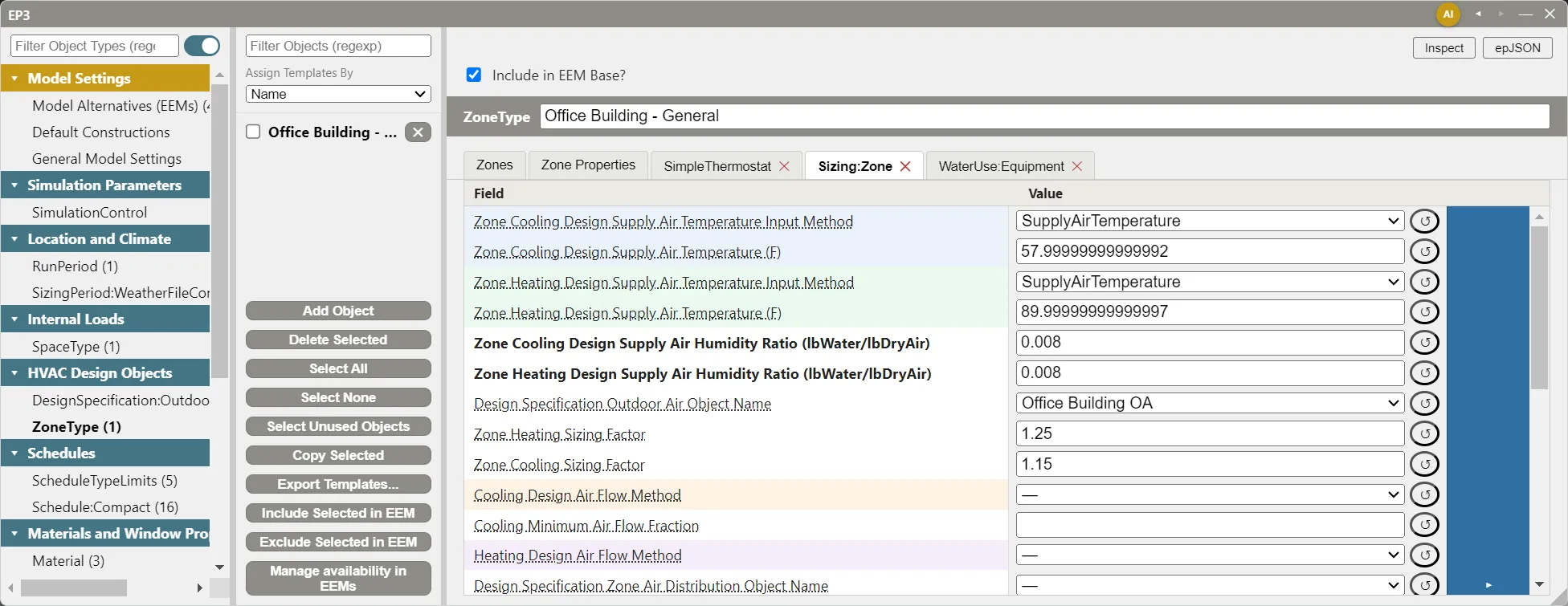
The fields below are grouped by what they control; the Input Output Reference documents each one.
6.2 Supply air conditions
Zone Cooling Design Supply Air Temperature Input Method and Zone Heating Design Supply Air Temperature Input Method choose between a fixed supply temperature (SupplyAirTemperature, the default) and a difference from the zone temperature (TemperatureDifference). The dialog shows Zone Cooling Design Supply Air Temperature or Zone Cooling Design Supply Air Temperature Difference to match, and likewise for heating. With the zone’s setpoint, the supply temperature sets the temperature difference the design airflow is calculated from (§6.7).
Zone Cooling Design Supply Air Humidity Ratio and Zone Heating Design Supply Air Humidity Ratio set the supply air’s moisture for sizing. Zone Load Sizing Method decides whether latent load enters sizing: the default, Sensible Load Only No Latent Load, sizes on sensible load and lets the zone humidity float. With Sensible Load, Latent Load, or Sensible And Latent Load, the zone humidity is controlled, and the two latent input methods show the humidity ratio or humidity ratio difference each uses.
6.3 Design air flow methods
Cooling Design Air Flow Method and Heating Design Air Flow Method set how the design airflow is found:
DesignDay(the default) uses the airflow from the design day calculation.Flow/Zoneuses the airflow entered in Cooling Design Air Flow Rate or Heating Design Air Flow Rate.DesignDayWithLimituses the design day airflow with a limit. For cooling, the larger of Cooling Minimum Air Flow per Zone Floor Area and Cooling Minimum Air Flow sets a lower limit on the design cooling airflow. For heating, Heating Maximum Air Flow per Zone Floor Area, Heating Maximum Air Flow, and Heating Maximum Air Flow Fraction set an upper limit on the design heating airflow; they never raise it.
The dialog shows the flow fields the chosen method uses. Cooling Minimum Air Flow Fraction is always shown, because EnergyPlus also uses it to size VAV terminal and fan minimum flows, whatever the method. The hidden flow fields are still exported, since EnergyPlus reads these limits during autosizing. Most zones use DesignDay; the limits matter mainly for VAV terminals (Air Loops, Branches, and Nodes).
6.4 Outdoor air and dedicated outdoor air
Design Specification Outdoor Air Object Name names the ventilation requirement the sizing calculation includes: a DesignSpecification:OutdoorAir for the whole zone, or a DesignSpecification:OutdoorAir:SpaceList that gives each of the zone’s spaces a requirement (Outdoor Air, Ventilation, and Energy Recovery). Design Specification Zone Air Distribution Object Name names the zone’s air distribution effectiveness.
Account for Dedicated Outdoor Air System (No by default) credits an ideal dedicated outdoor air system before the zone’s equipment is sized. With Yes, EnergyPlus calculates the heat the ventilation air adds or removes, from the minimum design ventilation flow and the difference between the DOAS supply temperature and the zone temperature, and includes it in the zone’s design load, so the zone equipment is sized for the net load after the DOAS air. Dedicated Outdoor Air System Control Strategy sets the assumed supply temperature, between Dedicated Outdoor Air Low Setpoint Temperature for Design and Dedicated Outdoor Air High Setpoint Temperature for Design. Both setpoints are Autosize by default, which uses EnergyPlus’s values for each strategy:
| Strategy | What the DOAS does | Setpoints when autosized |
|---|---|---|
NeutralSupplyAir (the default) |
Heats or cools outdoor air to keep it between the setpoints, adding little load either way | 21.1 °C and 23.9 °C (70 °F and 75 °F) |
NeutralDehumidifiedSupplyAir |
Cools and dehumidifies outdoor air to the low setpoint, then reheats it to the high setpoint | 14.4 °C and 22.2 °C (58 °F and 72 °F) |
ColdSupplyAir |
Delivers cool, dehumidified air that meets part of the sensible cooling load | 12.2 °C and 14.4 °C (54 °F and 58 °F) |
Set Account for Dedicated Outdoor Air System to Yes only for a zone served by a DOAS that behaves as the chosen strategy assumes (§8.2).
6.5 Sizing factors and Sizing:Parameters
Zone Heating Sizing Factor and Zone Cooling Sizing Factor multiply the zone’s design loads and airflows: a cooling factor of 1.15 sizes the zone’s cooling 15% above the design day result. When a factor is blank or zero, EnergyPlus uses the matching factor on Sizing:Parameters, a single model-wide object under HVAC Design Objects in the main object dialog.
6.6 Other fields
- Type of Space Sum to Use — for a zone of several spaces, whether the equipment is sized on the spaces’ coincident load (
Coincident, the default) or on the sum of their individual peaks (NonCoincident). EnergyPlus ignores it unless Do Space Heat Balance for Sizing is on inZoneAirHeatBalanceAlgorithm. - Heating Coil Sizing Method and Maximum Heating Capacity To Cooling Load Sizing Ratio — for heat pumps: size the heating coil on the cooling capacity, the heating capacity, or the greater of the two, with a cap on how far heating capacity may exceed the cooling load. The default,
None, leaves heat pump sizing unchanged. - Zone Humidistat Dehumidification Set Point Schedule Name and Zone Humidistat Humidification Set Point Schedule Name — the humidity setpoints used when latent sizing is on.
6.7 Worked example: design airflow from supply air temperature
EnergyPlus sizes a zone’s design cooling airflow from its sensible load and the difference between the zone temperature and the design supply air temperature: the mass flow is the load divided by the air’s specific heat times that difference. For standard air, the volume flow is:
Airflow [cfm] = Sensible Load [Btu/h] ÷ (1.08 × ΔT [°F]), or Airflow [L/s] = Sensible Load [W] ÷ (1.2 × ΔT [°C])
1.08 Btu/h per cfm·°F and 1.2 W per L/s·°C are the standard-air sensible heat factors of the ASHRAE Handbook—Fundamentals.
Take a zone with the Office Building - General template’s values: a cooling setpoint of 78.8 °F (26 °C), a Zone Cooling Design Supply Air Temperature of 58 °F (14.44 °C), and a Zone Cooling Sizing Factor of 1.15. Its design day sensible cooling load is 12,000 Btu/h.
- ΔT = 78.8 − 58 = 20.8 °F
- Airflow = 12,000 ÷ (1.08 × 20.8) = 12,000 ÷ 22.46 ≈ 534 cfm
- With the sizing factor: 534 × 1.15 ≈ 614 cfm
In SI: 12,000 Btu/h is 3,517 W, and ΔT = 26 − 14.44 = 11.56 °C. Airflow = 3,517 ÷ (1.2 × 11.56) ≈ 254 L/s, or 292 L/s with the sizing factor. 254 L/s is 537 cfm, within 1% of the IP result; the difference comes from the rounded air constants.
Lowering the supply temperature to 55 °F raises ΔT to 23.8 °F, and the design airflow falls to 12,000 ÷ (1.08 × 23.8) ≈ 467 cfm, or 537 cfm with the sizing factor. Less airflow means a smaller fan and smaller ducts, provided the coil can deliver 55 °F air at the conditions it will see. If it cannot, the zone receives less cooling than its design load at the design airflow (§8.2).
6.8 DesignSpecification:ZoneHVAC:Sizing
A DesignSpecification:ZoneHVAC:Sizing object sets how a zone unit’s supply airflows and capacities are sized, apart from the zone’s design airflow. Its airflow methods, for cooling, heating, and no-load operation, take a fixed flow, a flow per floor area, a fraction of the autosized flow, or a flow per unit of capacity; its capacity methods take a capacity, a capacity per floor area, or a fraction of the autosized capacity. Each method field shows only the field it uses. Create one under HVAC Design Objects in the main object dialog, then name it in a unit’s Design Specification ZoneHVAC Sizing Object Name, or in a ZoneType’s or zone’s Design Specification ZoneHVAC Sizing Object Name so that every unit serving those zones uses it (§4.3; Input Output Reference: DesignSpecification:ZoneHVAC:Sizing).
7. Zone multipliers
A zone’s Multiplier makes one modeled zone stand for several identical ones (Spaces and Zones). EnergyPlus multiplies the zone’s load and sends the multiplied load to the HVAC equipment that serves it, and autosizing accounts for the multiplier. The equipment needs no change: the zone keeps one copy of each unit, sized and simulated for the multiplied load.
8. Checking zone equipment and sizing
8.1 What EP3 checks
- Validate, in the top toolbar, runs these checks (Model Troubleshooting and Quality Assurance):
- Zone Thermostat Assignments: each zone has exactly one thermostat.
- Zone HVAC Equipment: each conditioned zone has a
Sizing:Zone, a thermostat, and equipment that responds to the thermostat. A zone with only some of the three fails, and a zone with none is warned as unconditioned. A zone whose conditioning equipment is all low-temperature radiant systems passes without a thermostat, and without aSizing:Zonewhen every capacity and flow is entered (an autosized one fails without aSizing:Zone), the same rule as the export (§5.5); a zone served only byAirTerminal:SingleDuct:ConstantVolume:NoReheatand without a thermostat is warned, because the zone floats. VAV, VAV reheat, powered induction, and constant volume reheat terminals need a thermostat like any other load-following equipment; another unit in the same zone brings back the three-part check. A zone whose only equipment is a heat pump water heater is warned, as the water heater does not condition the zone.Fan:ZoneExhaustand central exhaust systems do not count as equipment. AZoneType’s equipment, thermostat, andSizing:Zonecount on every zone it covers. - VRV Terminal Unit List Assignments, when the model has VRF equipment: each VRF terminal’s zone copy has an outdoor unit.
- The Assign HVAC Systems by Template tab warns about zones with no
Sizing:Zoneor more than one (§5.5). - The export reports each zone whose equipment is skipped, with the reason: no thermostat, more than one, or a zone that cannot be written.
8.2 Where sizing goes wrong
These checks catch structural problems. They do not test whether a zone’s Sizing:Zone assumptions match the equipment that serves it, and a mismatch gives a model that runs and reports unmet hours:
- A supply temperature the equipment cannot reach. A
Sizing:Zonethat assumes 55 °F supply air sizes a smaller airflow than one that assumes 58 °F (§6.7). If the coil cannot deliver 55 °F at the design entering conditions, the zone runs short of cooling at its design airflow. - A DOAS credit with no matching DOAS. With Account for Dedicated Outdoor Air System set to
Yes, the zone equipment is sized as if a DOAS conditions the ventilation air. If the zone’s outdoor air arrives untreated through the zone unit, or warmer or more humid than the strategy assumes, the equipment is undersized for the ventilation load it carries. - Equipment in the wrong order. A DOAS terminal listed after a fan coil (§5.3).
When a zone shows persistent unmet hours, check that its Sizing:Zone assumptions still match its equipment before concluding the equipment is too small. Model Troubleshooting and Quality Assurance covers diagnosing unmet hours. Air Loops, Branches, and Nodes and Central Plant Equipment and Plant Loops cover how zone sizing results carry into Sizing:System and Sizing:Plant.
This handbook is also built into EP3 (Help), where its EnergyPlus links open the EnergyPlus Reference. Technical specifications · Book a demo