Central Plant Equipment and Plant Loops
1. Overview
This chapter covers the PlantLoop and the central plant equipment on it: creating a loop, its branches, the boilers, chillers, cooling towers, pumps, and other equipment EP3 places on it, Sizing:Plant, the equipment lists and operation schemes that dispatch the equipment, and the setpoint managers that control the supply temperature.
A plant loop has a supply side, which holds the equipment that heats, cools, or rejects heat and the pump that moves the water, and a demand side, which holds the coils and other equipment that draw on the loop. The loop’s dialog also holds its Sizing:Plant, availability managers, equipment lists, and operation schemes. You place components and connect them; EP3 names every node and writes the Branch, BranchList, Connector:Splitter, Connector:Mixer, ConnectorList, PlantEquipmentList, and PlantEquipmentOperationSchemes objects at export.
The HVAC Outliner and Creating HVAC Systems covers the HVAC diagram, the HVAC Outliner, and the Draw Branch Connections and Erase Branch tools in general. Water heaters and service hot water loops are covered in Service Hot Water and Solar Water Heating, and chiller and boiler curves in Performance Curves: Part-Load and Efficiency Behavior.
The quickest way to a working central plant is a library system. The Fan Coil and DOAS with water coils templates bring a hot water loop with a boiler, a chilled water loop with a water-cooled chiller, and a condenser water loop with a cooling tower, complete with sizing, setpoint managers, and operation schemes (The HVAC Outliner and Creating HVAC Systems).
2. Creating a Plant Loop
2.1 The default plant loop
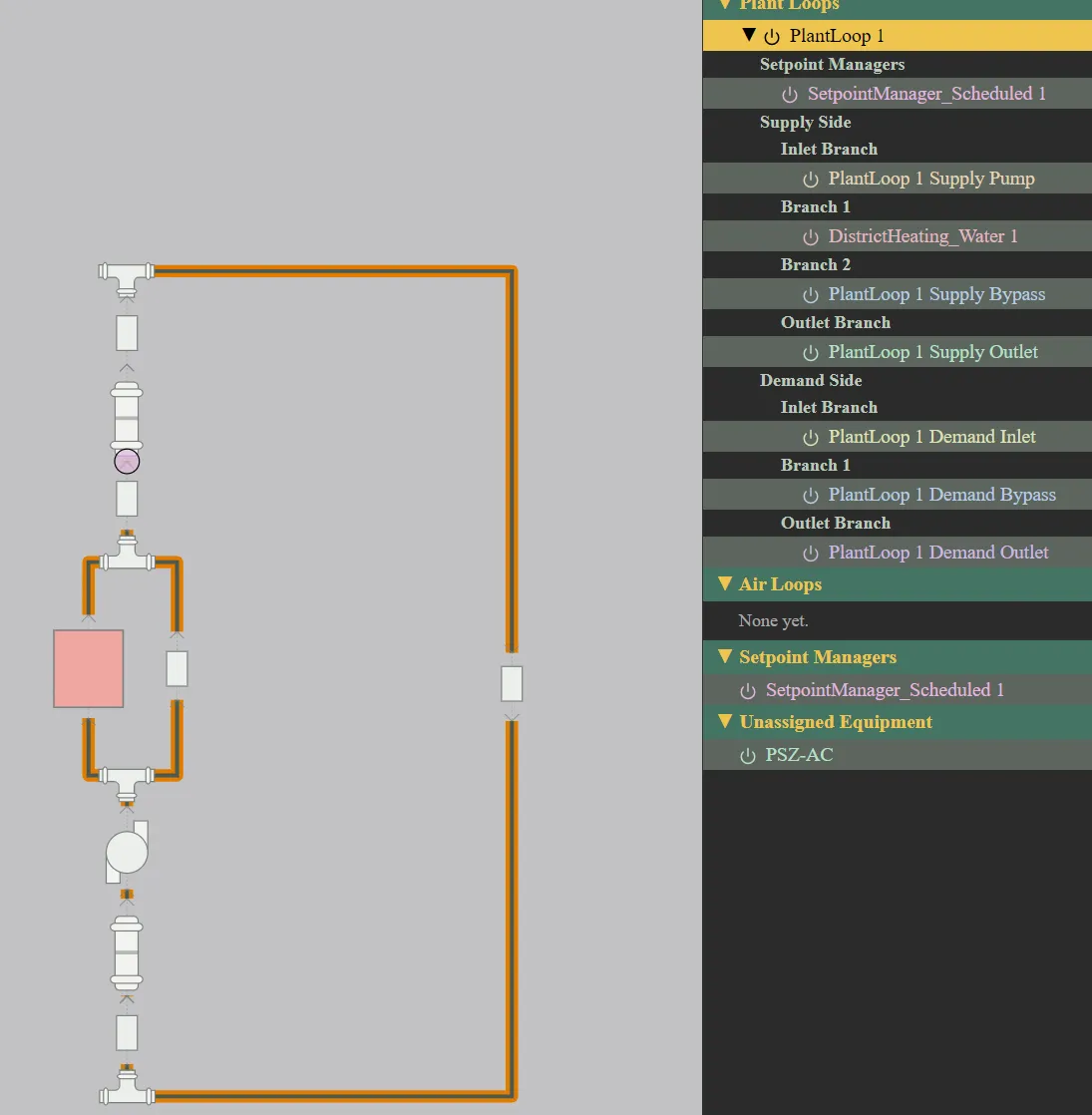
Add Plant Loop, in the HVAC Outliner’s toolbar, creates a complete heating loop in one undo step and selects it:
- The loop, named
PlantLoop 1(the next free number), with Maximum Loop Temperature 87°C (188.6°F) and Minimum Loop Temperature 66°C (150.8°F). - A
Sizing:Plantwith Loop TypeHeating, Design Loop Exit Temperature 82°C (179.6°F), and Loop Design Temperature Difference 11 K (19.8°F) (§7). - On the supply side: a
Pump:VariableSpeedon the inlet branch, aDistrictHeating:Waterand aPipe:Adiabaticbypass on two parallel branches, and aPipe:Adiabaticon the outlet branch. - On the demand side:
Pipe:Adiabaticobjects on the inlet branch, the outlet branch, and one parallel branch, the demand bypass. - A
PlantEquipmentListholding the district heating object, and aPlantEquipmentOperation:HeatingLoadthat runs that list for loads from 0 to 1,000,000,000 W on the Always On schedule (§9). - A
SetpointManager:Scheduledon the loop’s supply outlet, holding it at the Design Loop Exit Temperature through a constant schedule named<loop name> Supply Temperature(§10.1).
The pipes and the pump are named after the loop and their place on it, such as PlantLoop 1 Supply Pump and PlantLoop 1 Demand Bypass; renaming the loop renames those whose names you have not edited. Other new objects are named after their type and a number (DistrictHeating_Water 1). The two loop temperatures are calculated from Sizing:Plant when the loop is created and do not follow it afterwards (§7.3).
The default loop is a starting point. Replace the district heating object with a boiler, or turn the loop into a chilled water or condenser loop (§13). A new pump’s Design Maximum Flow Rate and Design Power Consumption start blank, and EnergyPlus reads a blank flow as zero: set both to Autosize, or enter values (§8). The district heating object’s Nominal Capacity also starts blank.
The diagram draws the loop as one vertical rail. The supply side sits in the middle, with water flowing up from the pump through the parallel branches to the supply outlet, bracketed by the plant inlet and plant outlet markers. The demand splitter sits at the top of the rail and the demand mixer at the bottom, with the demand branches to the right. The color swatch beside the loop’s name in its dialog sets the color of its lines, splitters, mixers, and markers.
2.2 The plant loop dialog
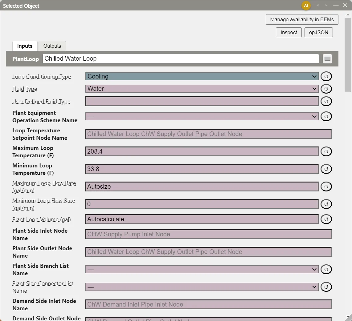
Double-click the loop’s row in the HVAC Outliner to open its dialog in the Selected Object dialog. From the top:
- Name and the color swatch.
- Loop Conditioning Type (§2.3).
- The
PlantLoopfields: Fluid Type (Waterby default), the two loop temperatures, Maximum Loop Flow Rate (Autosize), Minimum Loop Flow Rate (0), Plant Loop Volume (Autocalculate), Load Distribution Scheme (SequentialLoad), Plant Loop Demand Calculation Scheme (SingleSetpoint), and Common Pipe Simulation (None). EP3 fills in the node, branch list, connector list, and operation scheme names at export; the Loop Temperature Setpoint Node Name is the supply outlet node. - Availability managers (§11).
- The loop’s
Sizing:Plantfields (§7). - Equipment Lists and Operation Schemes (§9).
Load Distribution Scheme sets how EnergyPlus divides the load among the equipment an operation scheme turns on: SequentialLoad, the default, loads each piece of equipment to capacity, in the order of the equipment list, before starting the next. In simplified view, the plant equipment dialogs show only their main fields (The EP3 Interface and Model Settings).
2.3 Loop type and Loop Conditioning Type
Two fields describe what a loop does:
- Loop Type, in
Sizing:Plant:Heating,Cooling,Condenser, orSteam. It tells EnergyPlus how to size the loop and its equipment (§7). - Loop Conditioning Type, an EP3 field on the loop:
All,Heating,Cooling, orCondenser, plusSteamwhen the loop’s Fluid Type isSteam. It sets which equipment Draw Branch Connections offers to connect to the loop. It is not written to EnergyPlus.
Left blank, Loop Conditioning Type takes the Sizing:Plant Loop Type, and the dialog shows that value on a shaded background. Set it only to override the Loop Type: All lets any water component connect, on whichever side the component allows. Changing either field does not disconnect equipment already on the loop.
The main connections Draw Branch Connections offers, by Loop Conditioning Type:
| Loop | Supply side | Demand side |
|---|---|---|
| Heating | Boiler:HotWater, DistrictHeating:Water, the heating side of a CentralHeatPumpSystem, water heaters |
Hot water coils and reheat coils, water baseboards and radiant units, a chiller’s heat recovery side, an absorption chiller’s generator |
| Cooling | A chiller’s chilled water side, DistrictCooling, the cooling side of a CentralHeatPumpSystem |
Chilled water coils |
| Condenser | Cooling towers, fluid coolers, ground heat exchangers | A water-cooled chiller’s condenser side, a water-cooled VRF outdoor unit, water-to-air heat pump coils |
| Steam | Boiler:Steam |
Steam coils, an absorption chiller’s generator |
Every water loop also takes pumps on its supply side, Pipe:Adiabatic and the other pipes on either side, PlantComponent:TemperatureSource on its supply side, LoadProfile:Plant and WaterUse:Connections on its demand side, and either side of a HeatExchanger:FluidToFluid (§6.3).
2.4 Condenser and steam loops
A condenser loop is a PlantLoop whose Sizing:Plant Loop Type is Condenser. EnergyPlus also has a CondenserLoop object; EP3 works only with PlantLoop, and the importer reads a CondenserLoop as a PlantLoop (Importing EnergyPlus Files). The condenser loop’s supply side holds the heat rejection equipment, and its demand side the condensers of water-cooled chillers and other equipment that rejects heat to it.
A steam loop has Fluid Type Steam and Loop Type Steam. Its supply side holds a Boiler:Steam, a Pump:VariableSpeed:Condensate, and Pipe:Adiabatic:Steam pipes; its demand side holds steam coils.
3. Branch Architecture: Splitters, Mixers, and Filler Objects
3.1 Inlet, parallel, and outlet branches
Each side of a plant loop has the same shape: an inlet branch, a splitter, one or more parallel branches, a mixer, and an outlet branch. Every plant loop has its two splitters and two mixers from the moment it is created.
- The supply inlet branch holds the loop pump. The other inlet and outlet branches hold a
Pipe:Adiabaticunless you place something else there. - Each supply parallel branch usually holds one piece of equipment: a boiler, a chiller’s chilled water side, a cooling tower. A branch can also hold a pump ahead of its equipment, for a pump dedicated to that equipment.
- Each demand parallel branch holds one consumer: a coil’s water side, a baseboard, a chiller’s condenser.
EnergyPlus needs at least one component on every branch, and EP3 leaves an empty branch out of the export. Keep a component on every inlet and outlet branch, and at least one populated parallel branch on each side: the Validation dialog fails a side with none (§12).
3.2 Bypass branches
A bypass is a parallel branch that holds only a Pipe:Adiabatic. It carries the flow that the equipment on the other parallel branches does not take: on the supply side, the loop flow beyond what the operating equipment requests; on the demand side, the flow beyond what the coils’ valves pass. Keep the supply and demand bypasses of the default loop. A Pipe:Adiabatic passes water without adding or removing heat; use one wherever a branch needs a component but no equipment.
3.3 Connecting equipment
Every connection on a plant loop is made with Draw Branch Connections: click a node, then the node to connect it to (The HVAC Outliner and Creating HVAC Systems). The tool marks only the nodes that can take the component, by its fluid, the side of the loop, and the loop’s conditioning type (§2.3).
- To a splitter or mixer port: the component goes on an empty parallel branch of that side, or on a new parallel branch. Use this for supply equipment and for demand-side consumers.
- To a node on a branch: the component is inserted on that branch at that point, in series with what is there.
- Shift+click a branch node to choose a component type from the Add & Connect list and create it at that point, in series, in one step.
To replace a component, connect the new one to the old one’s inlet node, which places it beside the old one on the same branch, then select the old one and press Delete. Erase Branch moves the components of the branches you click to Unassigned Equipment (The HVAC Outliner and Creating HVAC Systems). Deleting a loop’s splitter, mixer, or boundary marker deletes the whole loop with its branches, Sizing:Plant, equipment lists, and operation schemes; its components move to Unassigned Equipment.
A component with several water connections, such as a chiller, sits on one branch for each. Connect each pair of nodes separately: a chiller’s chilled water inlet to the chilled water loop’s supply splitter port, then its condenser inlet to the condenser loop’s demand splitter port.
3.4 Demand branches for zone equipment and replicated air loops
A water coil of an air loop sits on its own demand branch (Air Loops, Branches, and Nodes). So does each water coil of zone equipment, such as a ZoneHVAC:FourPipeFanCoil or a ZoneHVAC:Baseboard:Convective:Water, which you connect once although it serves many zones (Zone-Level HVAC Equipment and Zone Sizing).
At export, a branch holding such a component is written once per copy of the component: once per zone the zone equipment serves, once per replicate of a replicated air loop (Air Loops, Branches, and Nodes), and once per copy of a replicated VRF outdoor unit. A fan coil assigned to 10 zones puts 10 parallel branches on the chilled water loop’s demand side and 10 on the hot water loop’s, named <zone name> <loop name> Demand Branch <n>. Because each copy takes the whole branch, Draw Branch Connections does not place such a component on a branch that holds anything else, or anything else on its branch. A branch whose component serves no zone yet is left out of the export, with a warning.
3.5 Branches in an EEM
Branch connections can differ by EEM, as on an air loop: a connection drawn or erased while an EEM other than Global is active is written to that EEM (Air Loops, Branches, and Nodes). Equipment that is off in an EEM is left off every branch in that EEM’s export. Several systems can therefore share one central plant: the Fan Coil and DOAS with water coils templates use the same three loops, and each system’s EEM writes the loops with only its own coils on the demand side (The HVAC Outliner and Creating HVAC Systems). A loop that is off in an EEM is not written at all.
Nodes are named after the component they leave, as on an air loop (Air Loops, Branches, and Nodes), and branches <loop name> Supply Branch <n> and <loop name> Demand Branch <n>, numbered in flow order.
4. Boilers and District Heating and Cooling
4.1 Boiler:HotWater
A Boiler:HotWater sits on a supply parallel branch of a heating loop. Add it from the Plant Equipment heading of the HVAC Components dialog and connect it to the loop’s supply splitter port. Its main fields:
| Field | Default | Notes |
|---|---|---|
| Fuel Type | NaturalGas |
Or electricity, fuel oil, propane, and other fuels. |
| Nominal Capacity | Autosize | |
| Nominal Thermal Efficiency | Required | Based on the fuel’s higher heating value. The Fan Coil template’s boiler uses 0.80. |
| Efficiency Curve Temperature Evaluation Variable, Normalized Boiler Efficiency Curve Name | Blank | A curve of part-load ratio, and optionally water temperature, that multiplies the efficiency (Performance Curves). |
| Design Water Flow Rate | Autosize | |
| Boiler Flow Mode | NotModulated |
ConstantFlow, LeavingSetpointModulated, or NotModulated. |
| Sizing Factor | 1 |
EnergyPlus autosizes every boiler on a loop to the loop’s full design load, multiplied by the boiler’s Sizing Factor. Two identical boilers that share the load need a Sizing Factor of 0.5 each; a lead and a standby boiler, each sized for the full load, keep 1. The operation scheme decides which runs when (§9).
4.2 DistrictHeating:Water and DistrictCooling
DistrictHeating:Water, on a heating loop’s supply side, and DistrictCooling, on a cooling loop’s supply side, model purchased hot or chilled water: they meet any load up to their Nominal Capacity, and their energy is reported as district heating or district cooling. They have no efficiency. Use them for a building served by a campus plant, or as placeholder equipment while the rest of a model is built.
5. Chillers
5.1 Chiller types
EP3 supports eight chiller types, listed under Plant Equipment in the HVAC Components dialog: Chiller:Electric:EIR, the usual electric chiller, with curves of the leaving chilled water temperature, the entering condenser temperature, and the part-load ratio; Chiller:Electric:ReformulatedEIR, with curves of the leaving condenser water temperature, for variable condenser flow; Chiller:Electric; Chiller:ConstantCOP, a fixed COP with no curves; the absorption chillers Chiller:Absorption and Chiller:Absorption:Indirect; and the fuel-driven Chiller:EngineDriven and Chiller:CombustionTurbine. Chiller:Electric:ASHRAE205 and the ChillerHeater:Absorption:* types are not available.
5.2 Chiller connections
A chiller has up to three water connections, each on its own branch, and usually each on its own loop:
| Connection | Goes on | Present when |
|---|---|---|
| Chilled Water | The supply side of a cooling loop | Always |
| Condenser | The demand side of a condenser loop | Condenser Type is WaterCooled (Chiller:Electric:ReformulatedEIR and the absorption chillers are always water cooled) |
| Heat Recovery | The demand side of a heating loop | Heat Recovery is Yes (the electric and fuel-driven chillers other than Chiller:ConstantCOP) |
| Generator | The demand side of a heating or steam loop | Absorption chillers |
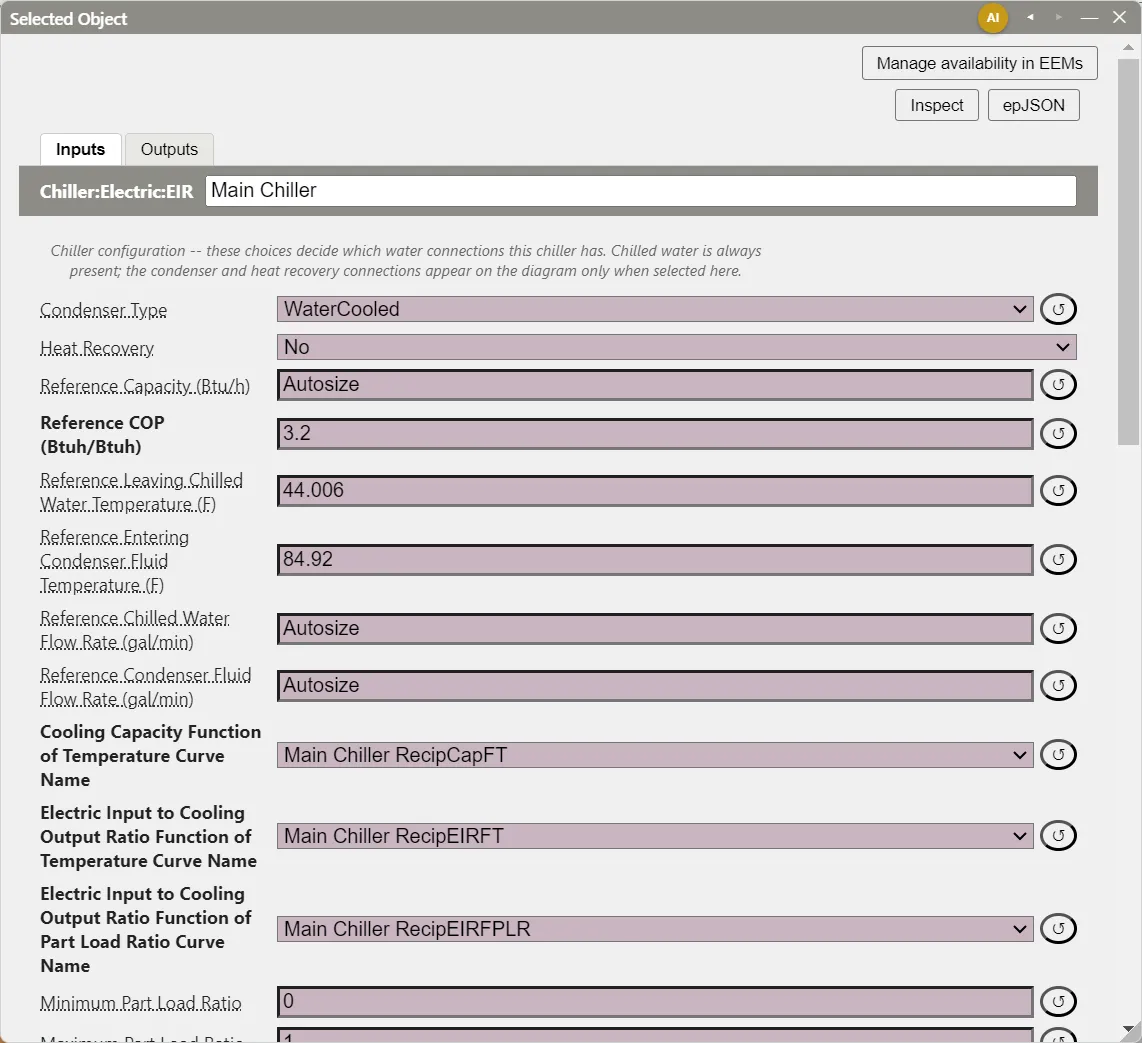
The chiller’s dialog leads with a Chiller configuration block holding the choices that decide these connections:
- Condenser Type —
WaterCooledshows the condenser connections;AirCooledandEvaporativelyCooledreject heat to outdoor air and have no condenser connection. The default depends on the type:WaterCooledforChiller:Electric:EIR;AirCooledforChiller:Electric,Chiller:ConstantCOP, and the fuel-driven chillers. - Heat Recovery —
Yessets Design Heat Recovery Water Flow Rate to Autosize and shows the heat recovery connections;Nosets the flow to 0.Chiller:Electric:EIRandChiller:Electricallow heat recovery only with aWaterCooledcondenser. - Generator Heat Source Type (absorption chillers) —
HotWaterconnects the generator to a heating loop,Steam(the default) to a steam loop.
A connection that a configuration choice switches off is hidden from the diagram and left out of the export, and the chiller keeps the branch it was on: switching an air-cooled chiller back to WaterCooled restores its condenser connection. A chiller is equipment on its chilled water loop only; its condenser and heat recovery sides do not appear in the other loops’ equipment lists.
5.3 Chiller:Electric:EIR fields
| Field | Default | Notes |
|---|---|---|
| Reference Capacity | Autosize | |
| Reference COP | Required | The Fan Coil template’s chiller uses 3.2. |
| Reference Leaving Chilled Water Temperature | 6.67°C (44.0°F) | |
| Reference Entering Condenser Fluid Temperature | 29.4°C (84.9°F) | |
| Reference Chilled Water Flow Rate, Reference Condenser Fluid Flow Rate | Blank | Set to Autosize. |
| Cooling Capacity Function of Temperature Curve Name, Electric Input to Cooling Output Ratio Function of Temperature Curve Name, Electric Input to Cooling Output Ratio Function of Part Load Ratio Curve Name | Required | The three performance curves. |
| Chiller Flow Mode | NotModulated |
LeavingSetpointModulated varies the chilled water flow to hold the leaving setpoint, for a variable-flow loop. |
| Sizing Factor | 1 |
A chiller added from the HVAC Components dialog has no curves: assign them, or start from a library system whose chiller has them (Performance Curves). Performance Curves works the chiller’s part-load curve. Every chiller on a loop autosizes to the loop’s full design load times its Sizing Factor, as boilers do.
Chiller:ConstantCOP needs only a Nominal Capacity, a Nominal COP, its flow rates, and its condenser type.
6. Heat Rejection and Other Plant Equipment
6.1 Cooling towers and fluid coolers
CoolingTower:SingleSpeed, CoolingTower:TwoSpeed, and CoolingTower:VariableSpeed sit on the supply side of a condenser loop. A cooling tower cools the condenser water by evaporation into the outdoor air, so its performance follows the outdoor wet-bulb temperature. Two terms describe a tower’s design:
- Range — the drop in water temperature across the tower: the condenser loop’s design temperature difference.
- Approach — how far the leaving water stays above the entering air’s wet-bulb temperature. A smaller approach needs a larger tower.
The main fields of CoolingTower:SingleSpeed:
| Field | Default | Notes |
|---|---|---|
| Design Water Flow Rate, Design U-Factor Times Area Value | Blank | Set to Autosize. |
| Design Air Flow Rate, Design Fan Power | Autosize | |
| Performance Input Method | UFactorTimesAreaAndDesignWaterFlowRate |
Or NominalCapacity, with Nominal Capacity. |
| Design Inlet Air Dry-Bulb Temperature, Design Inlet Air Wet-Bulb Temperature | 35°C (95°F), 25.6°C (78.1°F) | |
| Design Approach Temperature, Design Range Temperature | Autosize | |
| Capacity Control | FanCycling |
Or FluidBypass. |
FluidCooler:SingleSpeed and :TwoSpeed (dry, closed-circuit coolers) and EvaporativeFluidCooler:SingleSpeed and :TwoSpeed (closed-circuit coolers with spray water) also sit on a condenser loop’s supply side.
6.2 Ground heat exchangers and central heat pumps
GroundHeatExchanger:System— a vertical borefield on a condenser loop’s supply side, for water-source heat pump systems. ItsGroundHeatExchanger:Vertical:Sizing:Rectangleis created with it and edited in its dialog. Its site-specific values, such as the design flow, the ground properties, and the field dimensions, start blank and must be entered.GroundHeatExchanger:Pond,:Surface,:HorizontalTrench, and:Slinkyare also available.CentralHeatPumpSystem— a bank of chiller-heaters with three connections: a cooling side on a chilled water loop’s supply side, a heating side on a hot water loop’s supply side, and a source side on the demand side of a condenser loop.
6.3 HeatExchanger:FluidToFluid
A HeatExchanger:FluidToFluid moves heat between two loops. It is listed with the chillers and connects like one:
- Loop Supply Side — on the supply side of the loop it serves. To that loop it is equipment, like a chiller or a boiler.
- Loop Demand Side — on the demand side of the loop it draws from. To that loop it is a load, like a coil.
Use it for a secondary loop served from a primary loop, or for waterside economizing, with the condenser water loop cooling the chilled water loop directly. Its Control Type (UncontrolledOn by default) sets when it runs: the CoolingSetpoint*, HeatingSetpoint*, and DualDeadbandSetpoint* types hold the setpoint on its supply-side outlet node, which EP3 writes as the Heat Exchanger Setpoint Node Name; CoolingDifferentialOnOff runs it while the demand-side water is colder than the supply-side water. Heat Transfer Metering End Use Type (LoopToLoop by default) sets the end use its heat transfer is reported under, such as FreeCooling.
Water-to-water heat pumps (HeatPump:PlantLoop:EIR:*, HeatPump:WaterToWater:*) and headered pumps are not available in the HVAC Components dialog.
7. Sizing:Plant
7.1 Fields
Every plant loop owns one Sizing:Plant, created with the loop. Its fields are in the loop’s dialog, below the availability managers; it is not a separate object to select. Its Plant or Condenser Loop Name is filled in at export.
| Field | Default | Notes |
|---|---|---|
| Loop Type | Required | Heating, Cooling, Condenser, or Steam. A new loop starts at Heating. |
| Design Loop Exit Temperature | Required | The supply water temperature the loop is designed to deliver. A new loop starts at 82°C (179.6°F). |
| Loop Design Temperature Difference | Required | The design temperature change across the loop: the drop across a heating loop’s demand side, the rise across a cooling or condenser loop’s. A new loop starts at 11 K (19.8°F). |
| Sizing Option | NonCoincident |
Coincident sizes the loop flow from the loop’s coincident peak in a sizing simulation, and needs Do HVAC Sizing Simulation for Sizing Periods set to Yes in SimulationControl. |
| Zone Timesteps in Averaging Window, Coincident Sizing Factor Mode | 1, blank | Used by Coincident sizing. |
The Fan Coil template’s loops use these values:
| Loop | Loop Type | Design Loop Exit Temperature | Loop Design Temperature Difference |
|---|---|---|---|
| Hot Water Loop | Heating |
82°C (179.6°F) | 11 K (19.8°F) |
| Chilled Water Loop | Cooling |
7.22°C (45.0°F) | 6.67 K (12.0°F) |
| Condenser Water Loop | Condenser |
29.4°C (84.9°F) | 5.6 K (10.1°F) |
7.2 How a plant loop is sized
EnergyPlus sizes a plant loop from its demand side:
- Each coil’s capacity comes from the air side:
Sizing:ZoneandSizing:System(Air Loops, Branches, and Nodes). - Each coil’s design water flow is its capacity divided by ρ·cp·ΔT, where ΔT is the loop’s Loop Design Temperature Difference, unless the coil sets its own Design Water Temperature Difference.
- The loop’s design flow is the sum of the design flows of everything on its demand side. The pumps take this flow.
- Each piece of supply equipment is sized to deliver the loop’s design flow across the loop’s design temperature difference, times its Sizing Factor.
A larger design temperature difference gives less water flow for the same coil capacity, and so smaller pumps; it does not change the capacities. The equipment’s rated temperatures are not checked against Sizing:Plant: a chiller’s Reference Leaving Chilled Water Temperature (6.67°C by default) and a Coil:Heating:Water’s Rated Inlet Water Temperature (82.2°C) are separate fields to keep consistent with the loop’s design.
Worked example: chilled water flow. A chilled water loop’s coils add up to 351.7 kW (1,200,000 Btu/h, 100 tons), with the Fan Coil template’s Loop Design Temperature Difference of 6.67 K (12°F). With ρ = 1,000 kg/m³ and cp = 4,180 J/kg·K:
V = Q / (ρ · cp · ΔT) = 351,700 / (1,000 × 4,180 × 6.67) = 0.01261 m³/s = 12.6 L/s
In IP units, water carries 500 Btu/h per gpm per °F (8.33 lb/gal × 60 min/h × 1 Btu/lb·°F), so
gpm = Btu/h / (500 × ΔT) = 1,200,000 / (500 × 12) = 200 gpm
and 12.6 L/s × 15.85 gpm per L/s = 200 gpm. The chiller then autosizes to 1,000 × 4,180 × 6.67 × 0.01261 = 351.6 kW, the coils’ total. EnergyPlus evaluates the water properties at its own reference temperatures, so its sized values differ from these by about 1%. With a 16°F (8.9 K) temperature difference, the same coils need 1,200,000 / (500 × 16) = 150 gpm.
Worked example: condenser water flow. A water-cooled chiller rejects its cooling load plus its compressor power to the condenser loop: Qcond = Q × (1 + 1/COP). For the 351.7 kW chiller, with the template’s Reference COP of 3.2 and condenser loop temperature difference of 5.6 K:
Qcond = 351,700 × (1 + 1/3.2) = 461,600 W, and V = 461,600 / (1,000 × 4,180 × 5.6) = 0.0197 m³/s = 19.7 L/s
In IP units: 1,200,000 × 1.3125 = 1,575,000 Btu/h, and 1,575,000 / (500 × 10.08) = 312.5 gpm, which matches 19.7 × 15.85 = 312 gpm. The condenser loop carries about 1.56 times the chilled water flow, because its temperature difference is smaller and it also carries the compressor’s heat.
7.3 Loop temperature limits
Maximum Loop Temperature and Minimum Loop Temperature, on the loop itself, are the limits EnergyPlus allows the loop’s water to reach. A new loop sets them once from Sizing:Plant (§2.1); for a loop you turn into a cooling or condenser loop, set them again. EP3’s rule for a cooling or condenser loop is 5 K above the exit temperature plus the temperature difference, and 5 K below the exit temperature. For the chilled water loop above, that is 7.22 + 6.67 + 5 = 18.9°C (66.0°F) and 7.22 − 5 = 2.2°C (36.0°F).
8. Pumps
8.1 Fields, and two different kinds of curve
A plant loop needs a pump on its supply side; the Validation dialog fails a loop without one (§12). The loop pump sits on the supply inlet branch, where Add Plant Loop places a Pump:VariableSpeed. EP3 also has Pump:ConstantSpeed and, for steam loops, Pump:VariableSpeed:Condensate. To change the pump’s type, connect the new pump to the old pump’s inlet node and delete the old pump (§3.3).
The main fields of Pump:VariableSpeed:
| Field | Default | Notes |
|---|---|---|
| Design Maximum Flow Rate | Blank | Set to Autosize to take the loop’s design flow. EnergyPlus reads a blank value as zero. |
| Design Pump Head | 179,352 Pa (60 ft) | |
| Design Power Consumption | Blank | Set to Autosize to calculate it by the Design Power Sizing Method. |
| Motor Efficiency | 0.9 | |
| Coefficient 1 to Coefficient 4 of the Part Load Performance Curve | 0, 1, 0, 0 | The power fraction as a cubic in the flow fraction. |
| Pump Control Type | Continuous |
Intermittent runs the pump only while the loop has a load. |
| Design Power Sizing Method | PowerPerFlowPerPressure |
Or PowerPerFlow. |
| Design Electric Power per Unit Flow Rate | 348,701.1 W/(m³/s) (22 W/gpm) | Used by PowerPerFlow. |
| Design Shaft Power per Unit Flow Rate per Unit Head | 1.282051282 W/((m³/s)·Pa) | Used by PowerPerFlowPerPressure; the inverse of a 0.78 impeller efficiency. |
The pump’s part-load behavior is described two ways. The four Part Load Performance Curve coefficients are typed on the pump: the default 0, 1, 0, 0 makes power proportional to flow, and a cubic with a larger cubic term models a pump on a variable-speed drive (Performance Curves). Pump Curve Name refers to a curve object instead, the pump’s head against flow, used when the loop’s Pressure Simulation Type models pressure. Pump:ConstantSpeed has no part-load coefficients.
8.2 Worked example: pump power
With PowerPerFlowPerPressure, EnergyPlus calculates the pump’s design power as:
P = V × H × S / ηmotor
where V is the design flow, H the design head, and S the Design Shaft Power per Unit Flow Rate per Unit Head. For the 0.01261 m³/s (200 gpm) chilled water loop of §7.2, with the default head, S, and motor efficiency:
P = 0.01261 × 179,352 × 1.282051282 / 0.9 = 2,900 W / 0.9 = 3,222 W
That is 16.1 W/gpm. In IP units, the brake horsepower of a pump with impeller efficiency ηpump = 1 / 1.282 = 0.78 is
bhp = gpm × head (ft) / (3,960 × ηpump) = 200 × 60 / (3,960 × 0.78) = 3.885 hp
and the electric power is 3.885 / 0.9 = 4.317 hp × 745.7 W/hp = 3,219 W, the same within rounding. With PowerPerFlow and its default 22 W/gpm, the same pump would be sized at 0.01261 × 348,701 = 4,397 W. The 16°F loop of §7.2, at 150 gpm and the same head, needs 3,222 × 150 / 200 = 2,417 W.
9. Equipment Lists and Operation Schemes
9.1 Equipment lists
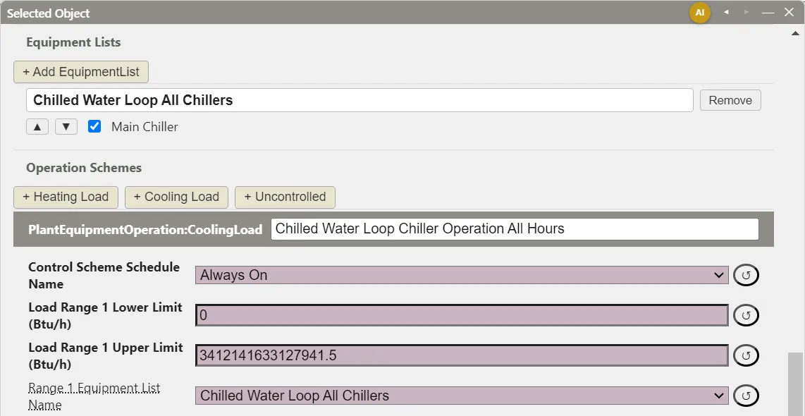
A PlantEquipmentList names the supply equipment an operation scheme may run, in order. A loop’s lists are in its dialog under Equipment Lists:
- + Add EquipmentList adds a list holding every piece of equipment on the loop’s supply parallel branches.
- Each list has a name field and a Remove button. Each piece of equipment has a checkbox: checked equipment is on the list, in the order shown, and ▲ and ▼ move it. Unchecked equipment is listed below, greyed.
- Equipment connected to the loop later joins every list, unless you uncheck it there.
The order matters for the SequentialLoad distribution scheme, which loads the first piece of equipment fully before starting the next (§2.2). A list’s membership and order can differ by EEM. An empty list is not written.
9.2 Operation schemes
An operation scheme decides which equipment list runs. Add one under Operation Schemes with + Heating Load, + Cooling Load, or + Uncontrolled:
PlantEquipmentOperation:HeatingLoadand:CoolingLoadrun a list by the size of the loop’s load: up to ten ranges, each with a Load Range Lower Limit and Load Range Upper Limit (in W) and a Range Equipment List Name. UseHeatingLoadon a heating loop, andCoolingLoadon a cooling or condenser loop.PlantEquipmentOperation:Uncontrolledruns its Equipment List Name whenever the loop has flow.
Each scheme also has a Control Scheme Schedule Name, which sets when the scheme applies, and a Remove button. EP3 writes the loop’s PlantEquipmentOperationSchemes from its schemes, in the order they were added, each with its schedule, up to ten. A scheme with no schedule, or whose list is missing or empty, is left out with an error; a loop with no scheme that can be written is left out of the export, with an error.
For example, a heating loop with a 300 kW and a 600 kW boiler can run the small boiler alone up to 300 kW, and both above that: Range 1 from 0 to 300,000 W on a list holding the small boiler, and Range 2 from 300,000 to 1,000,000,000 W on a list holding both.
The outdoor-condition, component-setpoint, and thermal-storage operation schemes are not available.
10. Setpoint Managers
10.1 The default setpoint
A plant loop’s supply equipment works to bring the loop’s supply outlet node to a setpoint. Add Plant Loop places a SetpointManager:Scheduled on the loop’s supply outlet, with Control Variable Temperature and a constant Schedule:Compact named <loop name> Supply Temperature at the Sizing:Plant Design Loop Exit Temperature: 82°C for the new heating loop. The schedule takes that value only when the loop is created. When you change the design temperature, change the schedule’s value with it (Schedules), or replace the manager; the Validation dialog warns when they differ (§12).
10.2 Adding and targeting a setpoint manager
Setpoint managers are added from the Setpoint Managers heading of the HVAC Components dialog and targeted in their Setpoints rows, as on an air loop (Air Loops, Branches, and Nodes). To target a plant loop’s supply outlet, choose the loop as the object and Plant Side Outlet as the node: the setpoint then stays on the supply outlet when the component at the end of the outlet branch changes. A setpoint manager is listed under each loop it targets in the HVAC Outliner, and drawn as a circle on each node it sets.
10.3 Types for plant loops
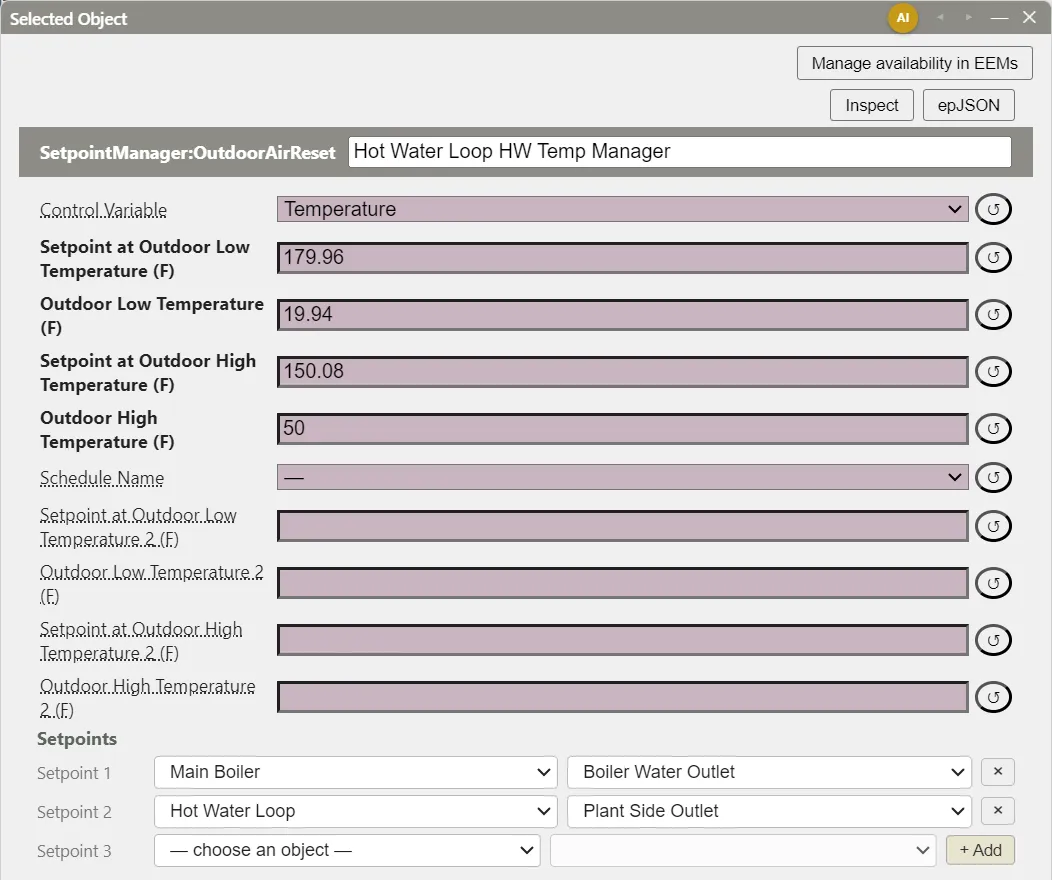
SetpointManager:Scheduled— a schedule’s value. A constant schedule holds a fixed supply temperature; the Fan Coil template’s condenser water loop is held at 29.4°C (85°F) this way.SetpointManager:OutdoorAirReset— resets the supply temperature linearly with the outdoor dry-bulb temperature. The Fan Coil template’s Hot Water Loop HW Temp Manager resets the hot water from 82.2°C (180°F) at −6.7°C (20°F) outdoors down to 65.6°C (150°F) at 10°C (50°F), on two nodes: Main Boiler’s Boiler Water Outlet and the Hot Water Loop’s Plant Side Outlet (its supply outlet). Its chilled water manager resets the chilled water from 6.7°C (44°F) at 26.7°C (80°F) outdoors up to 12.2°C (54°F) at 15.6°C (60°F).SetpointManager:FollowOutdoorAirTemperature— the outdoor wet-bulb (by default) or dry-bulb temperature plus an Offset Temperature Difference. On a condenser loop it holds the condenser water a fixed approach above the wet-bulb temperature.SetpointManager:CondenserEnteringResetand:CondenserEnteringReset:Ideal— reset the condenser water temperature to lower the combined chiller and tower energy. The ideal type searches for the optimum each time step, within a Minimum Lift (11.1 K, 20°F) and a Maximum Condenser Entering Water Temperature (32°C, 89.6°F).SetpointManager:ReturnTemperature:ChilledWaterand:HotWater— reset the supply temperature to hold a return temperature: for chilled water, 13°C (55.4°F) by default, with the supply between 5 and 10°C (41 and 50°F). Return Temperature Setpoint Input Type has no default. Target any node of the loop: EP3 fills in the loop’s supply inlet and outlet nodes at export.
SetpointManager:FollowGroundTemperature, :FollowSystemNodeTemperature, and :Scheduled:DualSetpoint also work on plant nodes.
A chilled water loop reset upward, or a hot water loop reset downward, delivers less capacity at the reset end, so check unmet hours when the reset reaches into high loads.
11. Availability Managers
A plant loop’s availability managers decide when its pumps may run, in addition to the pumps’ schedules. They are listed in the Availability managers section of the loop’s dialog: + Add… adds one, each manager has a tab, and ◀ and ▶ set the order. EnergyPlus evaluates a plant loop’s managers in order, and the first that reports anything other than NoAction decides. Typical plant managers are AvailabilityManager:LowTemperatureTurnOff and :HighTemperatureTurnOff, which lock a heating or cooling loop out by outdoor temperature, and AvailabilityManager:DifferentialThermostat, which runs a loop while one node is warmer than another. A plant loop cannot use AvailabilityManager:NightCycle or :NightVentilation. Controllers and Availability Managers covers each manager type and how their statuses combine.
12. Checking Your Work
The Validation dialog has a card for each plant loop under Plant Loops, headed with its loop type and Design Loop Exit Temperature, with four checks (Model Troubleshooting and Quality Assurance):
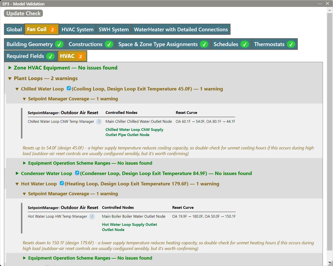
- Setpoint Manager Coverage lists the loop’s setpoint managers by family. It fails when no setpoint manager controls the loop’s supply outlet. It warns when the supply setpoint does not come within 1 K (1.8°F) of the
Sizing:PlantDesign Loop Exit Temperature, and when a reset takes a heating loop more than 3 K (5.4°F) below it, or a cooling loop more than 3 K above it. A node set by more than one manager is a warning, or a failure when aSetpointManager:Scheduledis one of them. - Branch Components fails a side with no populated parallel branch.
- Supply Side Pump fails a loop with no pump on its supply side.
- Equipment Operation Scheme Ranges fails a heating or cooling load scheme whose Range 1 is incomplete, whose ranges skip a number, or whose range is missing a limit or a list.
The fan coil office’s hot water loop, for example, shows a reset warning: its outdoor air reset reaches 65.6°C (150°F), 16.4 K (29.5°F) below its 82°C (179.6°F) design.
After a run, the Component Sizing Summary lists the autosized values of each pump, boiler, chiller, and tower, and every node a setpoint manager sets reports its temperature, so the loop’s operation can be checked against its setpoint (Viewing and Interpreting Results). A NodeReport adds output at other plant nodes (Air Loops, Branches, and Nodes).
13. Worked Example: A Chilled Water and Condenser Water Plant
This example builds the chilled water and condenser water loops of §7.2 from two default loops, for a model whose cooling coils are already in place. The Fan Coil template’s plant is a finished system of this kind.
- Add the chilled water loop. Click Add Plant Loop and rename the loop
Chilled Water Loop. - Set its sizing. In
Sizing:Plant, set Loop Type toCooling, Design Loop Exit Temperature to 7.22°C (45°F), and Loop Design Temperature Difference to 6.67 K (12°F); Loop Conditioning Type follows. Set Maximum Loop Temperature to 18.9°C (66°F) and Minimum Loop Temperature to 2.2°C (36°F) (§7.3). - Set the setpoint. Change the value of the
Chilled Water Loop Supply Temperatureschedule from 82°C to 7.22°C (45°F). - Replace the equipment. Add a
Chiller:Electric:EIRfrom the HVAC Components dialog. With Draw Branch Connections on, click its chilled water inlet node, then the inlet node ofDistrictHeating_Water 1; then delete the district heating object. Enter the chiller’s Reference COP (3.2), its three curves, and Autosize for its two reference flow rates (§5.3). The equipment list now holds the chiller. - Set the operation scheme. Click + Cooling Load, and set Control Scheme Schedule Name to Always On, Load Range 1 from 0 to 1,000,000,000 W, and Range 1 Equipment List Name to the loop’s list. Remove the heating load scheme.
- Set the pump. Set Design Maximum Flow Rate and Design Power Consumption to Autosize. With the default head, the pump sizes to about 3.2 kW at 200 gpm (§8.2).
- Add the condenser loop. Add a second loop,
Condenser Water Loop, with Loop TypeCondenser, exit temperature 29.4°C (85°F), temperature difference 5.6 K (10.1°F), loop temperatures 40°C (104°F) and 24.4°C (75.9°F), and its supply temperature schedule at 29.4°C (85°F). - Add the tower. Replace its district heating object with a
CoolingTower:SingleSpeed, as in step 4, with Design Water Flow Rate and Design U-Factor Times Area Value set to Autosize. Set its operation scheme and pump as in steps 5 and 6. - Connect the condenser. Click the chiller’s condenser inlet node, then the condenser loop’s demand splitter port. Condenser Type must be
WaterCooled, the default forChiller:Electric:EIR. - Connect the coils. Click each cooling coil’s water inlet node, then the chilled water loop’s demand splitter port (§3.4).
- Validate and simulate. Click Validate: under Plant Loops, each card shows a setpoint manager on the supply outlet at the design exit temperature, and no failures. Simulate (Running Simulations) and check the sized chilled water flow against 2 gpm per ton (0.0359 L/s per kW) (§7.2).
14. Where to Go Next
- The HVAC Outliner and Creating HVAC Systems — the HVAC diagram, the outliner, library systems, and the Draw Branch Connections and Erase Branch tools.
- Zone-Level HVAC Equipment and Zone Sizing — fan coils, baseboards, and other zone equipment on a plant loop’s demand side.
- Air Loops, Branches, and Nodes — air loop water coils,
Sizing:System, and replicated air loops. - Performance Curves: Part-Load and Efficiency Behavior — chiller and boiler curves.
- Service Hot Water and Solar Water Heating — water heaters and service hot water loops.
- Controllers and Availability Managers — plant loop availability managers.
- Energy Efficiency Measures (EEMs) — shared plants and system alternatives.
- Model Troubleshooting and Quality Assurance — the Validation dialog and unmet hours.
This handbook is also built into EP3 (Help), where its EnergyPlus links open the EnergyPlus Reference. Technical specifications · Book a demo