The HVAC Outliner and Creating HVAC Systems
1. Overview
This chapter covers the two tools on the HVAC side of the EP3 window, the HVAC diagram and the HVAC Outliner, and the ways to put an HVAC system into a model:
- import a complete system from the template library, through the Model Wizard or the Import dialog (§3);
- build one from loops and individual components (§5);
- save a system you have built as a template of your own, for reuse in other models (§6).
Other chapters go into more depth. Air Loops, Branches, and Nodes covers AirLoopHVAC topology, terminals, and setpoint managers. Central Plant Equipment and Plant Loops covers plant loops and their equipment. Zone-Level HVAC Equipment and Zone Sizing covers zone equipment and the order in which it serves a zone. Controllers and Availability Managers covers the objects that switch equipment on and off.
Two EnergyPlus terms run through this chapter. A node is a point in the system where EnergyPlus tracks the condition of the air or water passing through: temperature, flow rate, humidity. A branch is an ordered run of one or more components in series, inlet node to outlet node. Each side of a loop, supply and demand, is built from branches: an inlet branch, any parallel branches between a splitter and a mixer, and an outlet branch. EP3 writes the Branch, BranchList, Connector:Splitter, and Connector:Mixer objects and the node names at export; you work with the components and the connections between them.
2. The HVAC side of the window
The HVAC side sits to the right of the building geometry side, and both are visible at all times (The EP3 Interface and Model Settings). The HVAC diagram takes most of the HVAC side, and the HVAC Outliner runs down its right edge. Selecting an object in either one selects it in the other, and its fields appear in the Selected Object dialog.
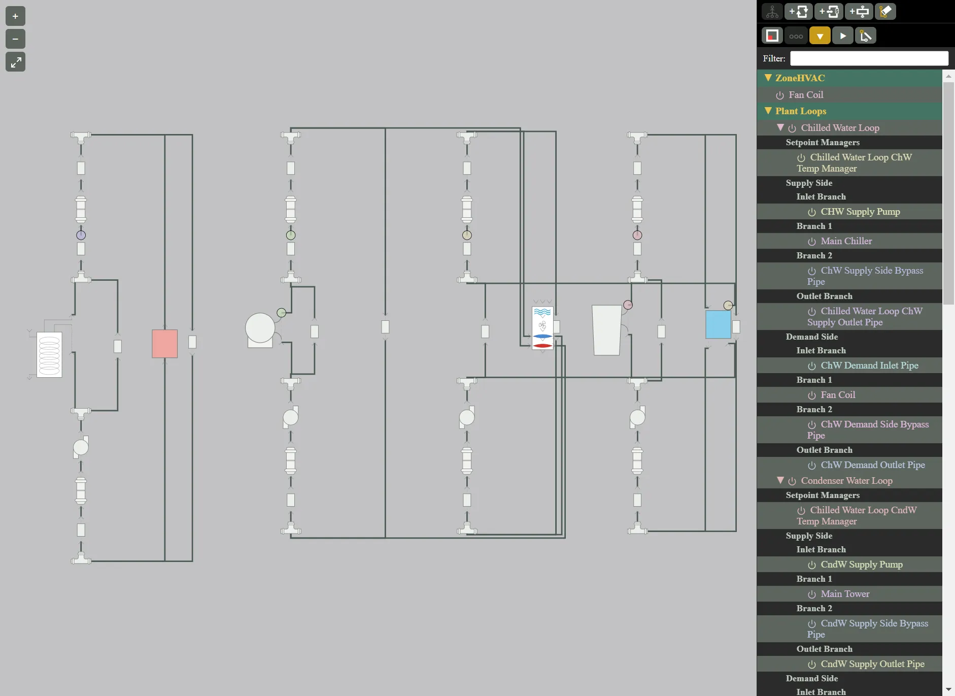
2.1 The HVAC diagram
The diagram draws each PlantLoop and condenser loop with its supply and demand sides, each AirLoopHVAC with its outdoor air system and terminals, and every component with its node connections. Air nodes and water nodes are drawn differently, so a coil’s air side and water side can be told apart at a glance.
- Selecting. Click an object to select it. Ctrl+click adds to the selection, Shift+click toggles an object in or out of it, and Ctrl+Shift+click removes it. Dragging on empty canvas draws a selection rectangle: left to right selects what lies wholly inside, right to left selects what it touches. Clicking a loop’s splitter, mixer, or boundary marker selects the whole loop.
- Moving and rotating. The Select, Move, Rotate, and Erase tools in the top toolbar work in the diagram as they do in the 3D view; the other drawing tools act as Select there. Moving an object changes only where it is drawn. Hold Ctrl while moving to copy; right after the copy, type a count followed by
xand press Enter to repeat it, so5xmakes five evenly spaced copies in all, for example of a zone’s equipment. - Deleting. The Delete key, or the Erase tool, deletes the selected objects. Deleting a loop’s splitter, mixer, or boundary deletes the whole loop; deleting zone equipment removes it from every zone that lists it.
- Viewing. The +, −, and Zoom Extents buttons in the diagram’s corner control the view, and dragging with the middle mouse button pans it.
2.2 The HVAC Outliner
The HVAC Outliner lists the model’s HVAC objects in five sections. Click a section header to collapse or expand it.
- ZoneHVAC — zone equipment: air terminals, fan coils, packaged terminal units, VRF terminal units, water-to-air heat pumps, baseboards, radiant systems, ideal loads air systems, and zone exhaust fans. Equipment with a water connection, such as a fan coil, is also listed on its loop’s branch. A unit’s fan, coils, and outdoor air mixer are not listed separately; they are edited in the unit’s dialog.
- Plant Loops — one entry per
PlantLoopand condenser loop. Under each loop come its Setpoint Managers, then Supply Side and Demand Side, each broken into Inlet Branch, Branch 1, Branch 2, and so on, and Outlet Branch, with the components on each branch. - Air Loops — one entry per
AirLoopHVAC, laid out the same way. The supply side’s outdoor air system adds an Outdoor Air Stream and a Relief Stream for each outdoor air mixer, and the Demand Side lists the loop’s terminals and plenums. - Setpoint Managers — every setpoint manager in the model. A setpoint manager can control nodes on more than one loop, or on none, so each one is listed here as well as under the loops it controls.
- Unassigned Equipment — components that sit on no branch: a component you have added but not connected (§5.2), one whose branch you erased (§5.4), or an air-cooled VRF outdoor unit, which has no water connection to place on a loop.
Working with the rows:
- Click a row to select the object; the same Ctrl and Shift modifiers as the diagram apply. Clicking a loop’s row selects the whole loop.
- Double-click a row to open the object in the Selected Object dialog. A setpoint manager opens in the main object dialog instead.
- Hover over a loop, branch, or component row to highlight it in the diagram. A row’s name is drawn in the same color as the object’s label in the diagram.
- The triangle beside a loop’s name collapses or expands that loop alone.
- The power button at the start of each row switches the object on or off in the active EEM. Objects that are off in the active EEM are hidden unless the Objects that are off in this EEM toggle in the top toolbar is on (Energy Efficiency Measures (EEMs)).
- The Filter box above the sections narrows every section to the names that contain what you type.
Availability managers are not listed in the outliner. They are edited in the dialog of the object they control: an air loop’s or plant loop’s dialog lists its availability managers (Controllers and Availability Managers).
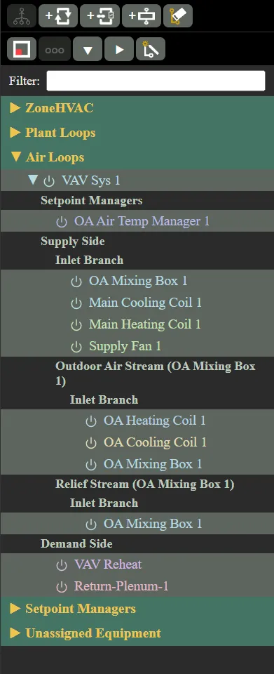
2.3 The toolbars
The outliner’s two toolbar rows hold these buttons:
| Button | Action |
|---|---|
| Add Plant Loop | Creates a new plant loop (§5.1). |
| Add AirLoopHVAC | Creates a new air loop (§5.1). |
| Add HVAC Component | Opens the EP3 - HVAC Components dialog (§5.2). |
| Erase Branch | Switches the Erase Branch mode on or off (§5.4). |
| View Zone HVAC Assignments | Opens EP3 - Select Zone Conditioning Equipment (§3.2). |
| Expand All, Collapse All | Expand or collapse every section. |
| Draw Branch Connections | Switches the Draw Branch Connections mode on or off (§5.3). |
Two more buttons tidy a model’s HVAC, each as one undo step:
- Consolidate merges identical zone equipment that serves different zones into one object assigned to all of them, then merges identical air loops that serve different zones into one loop, replicated per zone. Objects merge only when everything but their names and zones matches, in every EEM. A message lists what was merged.
- Organize closes the empty space between loops in the HVAC diagram, with the same layout the importer uses. Connections do not change.
A mode’s button is highlighted in gold while the mode is on, and a line of instructions appears across the bottom of the diagram. Draw Branch Connections and Erase Branch cannot be on at the same time, and choosing a drawing tool in the top toolbar switches either one off.
3. Creating a system from a template
Most systems get into a model from the HVAC template library. The Model Wizard’s HVAC Systems tab lists the systems that ship with EP3 in the HVAC and SWH Systems file, under EP3 Library > Systems, where each system is an EEM of the file: air loop systems such as AirLoopHVAC Water Coils VAV Reheat, DOAS with water coils, and the Packaged VAV systems, and zone equipment systems such as Fan Coil, PSZ-AC, PSZ-HP, PTAC, PTHP, VRV, HW Baseboard, and the water-to-air heat pump systems. Templates you have saved (§6) appear under User Library, from the folders under Library Locations. After the Wizard, the same library is available from the Import button in the top toolbar, on the Library templates tab. The Model Wizard covers the tab and its options.
Each template is complete: every loop, component, curve, and schedule the system needs comes with it. The air loop systems except DOAS with water coils run on an office HVAC operation schedule (weekdays 6:00 to 22:00, Saturdays 6:00 to 18:00, from the DOE reference office buildings), start early with an optimum start over the zones they serve, and cycle at night to hold the setback setpoints. For another building type, change the fans’ availability schedule, and the loop’s night cycle and optimum start follow it (Air Loops, Branches, and Nodes). Once imported, the system appears in the HVAC diagram and the HVAC Outliner like any other: a system built on an AirLoopHVAC or PlantLoop appears under Air Loops or Plant Loops with its branches and setpoint managers in place, and its zone units and terminals appear under ZoneHVAC.
3.1 Each system becomes an HVAC EEM
Every HVAC system you import from the library becomes a separate Energy Efficiency Measure, named for the template (PSZ-AC, Fan Coil, and so on) and tagged as an HVAC alternative. The system’s objects are stored in the Global model, and its EEM is the alternative that switches them on, so selecting the Fan Coil EEM in the EEM dropdown shows the fan coil system and hides the others. When the model has a service water heating EEM, a new HVAC EEM uses it as its parent, so the water heating system comes along with every HVAC alternative.
Whatever you add to the HVAC side while an HVAC EEM is active, such as a loop, a component or a setpoint manager, is stored in the Global model and switched on in that EEM, so it becomes part of that system and stays off in the other HVAC alternatives. Added while Global or an ordinary EEM is active, it is on wherever the Global model is.
Systems that share a central plant share it in the model. The Fan Coil and DOAS with water coils templates, for example, use the same hot water, chilled water, and condenser loops; importing both gives one set of loops with a coil branch for each system, and each system’s EEM switches on that system’s equipment. Energy Efficiency Measures (EEMs) covers system alternatives and combining them.
3.2 Assigning zone equipment
A zone is conditioned only by the zone equipment it lists. The Model Wizard assigns each imported system’s zone equipment (its terminals or zone units) to every ZoneType it imported, so the zones of those types use it from the start. The Import dialog asks where to make the assignment: At Global, In each system’s new EEM (the default), or None (assign them later).
To review or change the assignments, click View Zone HVAC Assignments in the outliner’s toolbar. It opens EP3 - Select Zone Conditioning Equipment, with one tab for assigning equipment by ZoneType and one for assigning it zone by zone. The Model Wizard covers the dialog, and Zone-Level HVAC Equipment and Zone Sizing covers equipment order and load distribution.
4. Choosing a system type: ZoneHVAC vs. AirLoopHVAC
Every system in the library, and most components in the HVAC Components dialog, belong to one of two families, and the outliner’s sections reflect the split: zone equipment listed under ZoneHVAC, and air loop systems that build out a supply and demand side under Air Loops.
ZoneHVAC equipment (PTAC, PTHP, fan coils, water-to-air heat pumps, VRF terminal units, and similar) conditions one zone at a time. These systems simulate faster than an equivalent air loop, because EnergyPlus has no central mixed-air path or branch network to solve. Each unit runs a built-in control scheme, with less room to change how its fan, coils, and flow rates operate. Outdoor air is the clearest example: a unit’s outdoor air follows its fan and its outdoor air fields, and there is no shared airstream to economize on, to coordinate ventilation across zones, or to recover heat from.
AirLoopHVAC systems (packaged rooftop units, built-up VAV systems, DOAS) route zones through a shared central airstream, mixing return and outdoor air at a controlled point before the main coils. That mixed-air path is what makes economizers, coordinated ventilation control, and central heat recovery possible (Air-Side System Fundamentals). The cost is more nodes, branches, and control objects, and a longer simulation.
The choice follows what the building needs. A building with modest, zone-independent loads and little economizer opportunity is often represented well by zone equipment; a building where ventilation energy or economizer savings matter needs the central airflow control of an air loop. In the EP3 Library, PSZ-AC, PSZ-HP, PTAC, PTHP, Fan Coil, VRV, HW Baseboard, and the water-to-air heat pump systems are zone equipment systems; AirLoopHVAC Water Coils VAV Reheat, the gas furnace air handler, DOAS with water coils, and the Packaged VAV systems are air loop systems.
5. Building a system from components
A system can be assembled piece by piece, or a template system extended, with the outliner’s toolbar buttons. The usual order is to create the loops, add the components, and connect them with Draw Branch Connections.
5.1 Adding a loop
- Add Plant Loop creates a complete, minimal plant loop and selects it: a
Pump:VariableSpeedon the supply inlet branch, aDistrictHeating:Waterand aPipe:Adiabaticbypass on two parallel supply branches,Pipe:Adiabaticplaceholders on the remaining inlet and outlet branches, and aPipe:Adiabaticbypass on the demand side. It starts as a heating loop, with aSizing:Plant. Replace the district heating object with the loop’s equipment, and set the loop’s type and sizing in its dialog (Central Plant Equipment and Plant Loops). - Add AirLoopHVAC creates a complete default air loop and selects it: an
OutdoorAir:Mixer, aCoil:Heating:Water, aCoil:Cooling:Water, and aFan:VariableVolumeon the supply side, in that order of flow, with the mixer’s outdoor air and relief streams empty; aSizing:System; and aSetpointManager:Scheduledon the supply outlet. The demand side starts empty. The coils’ water sides are connected to plant loops, and the loop’s terminals to its demand side, with Draw Branch Connections (§5.3).
Each new loop is placed beside the existing loops in the diagram. Air Loops, Branches, and Nodes covers the air loop’s parts in detail.
5.2 Adding a component
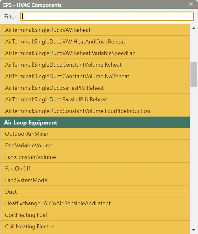
Add HVAC Component opens EP3 - HVAC Components, a list of every component EP3 can add, under five headings:
- ZoneHVAC — zone units and air terminals, from
ZoneHVAC:IdealLoadsAirSystemand the baseboards toZoneHVAC:FourPipeFanCoil,ZoneHVAC:PackagedTerminalAirConditioner,ZoneHVAC:TerminalUnit:VariableRefrigerantFlow, and theAirTerminal:SingleDuct:*terminals. - Air Loop Equipment — fans, coils,
OutdoorAir:Mixer, heat exchangers, theAirLoopHVAC:Unitary*systems, DX coil systems, and plenums. - Setpoint Managers — every setpoint manager type.
- Service Hot Water — the water heaters and heat pump water heaters.
- Plant Equipment — boilers, chillers, cooling towers, pumps, pipes, district heating and cooling, ground heat exchangers, the VRF outdoor units, and
WaterUse:Connections.
The Filter box narrows the list to matching type names. Click a type to add a new object of it. The new object follows the pointer in the diagram, and the next click in the diagram places it. The dialog stays open, so you can add and place several components in a row; close it with its ✕ or by clicking Add HVAC Component again.
A component you add starts unconnected: it appears in the diagram and, if it belongs on a branch, under Unassigned Equipment in the outliner. Zone equipment is listed under ZoneHVAC and serves no zone until it is assigned to one (§3.2). The equipment is covered field by field in Zone-Level HVAC Equipment and Zone Sizing and Central Plant Equipment and Plant Loops.
5.3 Draw Branch Connections
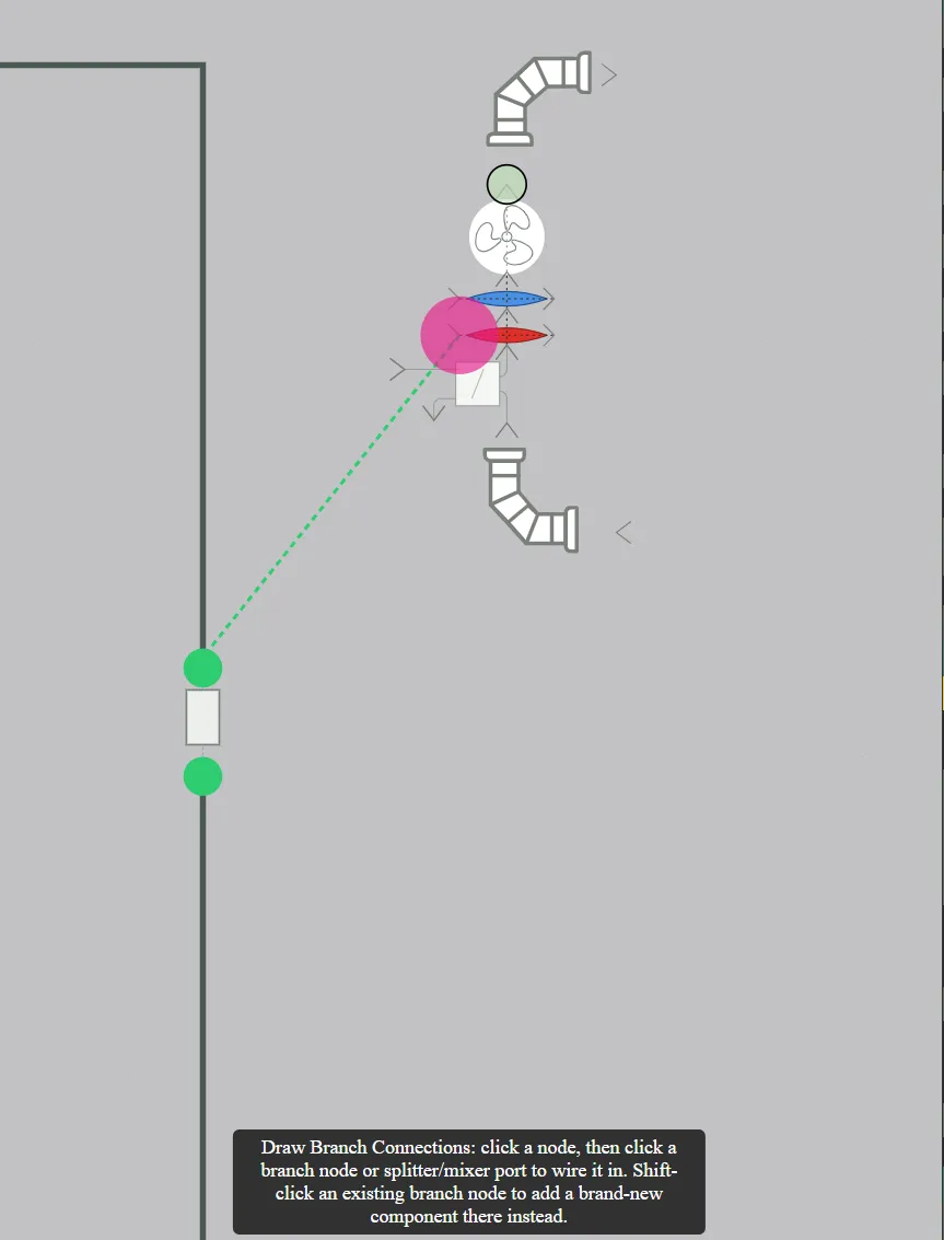
Draw Branch Connections connects components to loops. While it is on, every node you can connect is marked with a dot in the diagram.
- Click a node: an unconnected component’s node, or a node on a branch.
- Click the node to connect it to: a branch node, or a splitter or mixer port. A dashed line follows the pointer from the first pick until you do.
The second click makes the connection. Connecting a component to a node on a branch places it on that branch; connecting it to a splitter or mixer port puts it on an empty parallel branch, or on a new one. A second click that makes no valid connection clears the first pick, and a click that misses every node is ignored, leaving the first pick in place. The connections a component can make depend on its nodes: a water coil’s air node goes on an air loop’s supply side, outdoor air stream, or relief stream, and its water nodes go on a plant loop’s demand side. A terminal is connected by clicking the air loop’s supply outlet node, then the terminal’s inlet. Air Loops, Branches, and Nodes and Central Plant Equipment and Plant Loops cover what each connection does to the loop.
Shift+click to add and connect in one step. With Draw Branch Connections on, Shift+click a node on a branch as the first pick. An Add & Connect list opens with only the component types that can connect at that node. Choosing one creates a new object of that type, places it on the branch at that point, and selects it, as one undo step. A Shift+click on an unconnected component’s node is treated as an ordinary first pick.
5.4 Erase Branch
Erase Branch is the reverse of Draw Branch Connections. While it is on, click a branch’s connector line, or drag across several, to remove those branches. Their components are not deleted: they move to Unassigned Equipment, ready to be connected elsewhere. To delete a component or a whole loop, select it and press Delete (§2.1).
5.5 VRF systems
A VRF system is built around one or more outdoor units (AirConditioner:VariableRefrigerantFlow or AirConditioner:VariableRefrigerantFlow:FluidTemperatureControl), each serving a set of terminal units: ZoneHVAC:TerminalUnit:VariableRefrigerantFlow in the zones, or AirLoopHVAC:TerminalUnit:VariableRefrigerantFlow on an air loop. An outdoor unit and its terminals are joined by refrigerant, which EnergyPlus models as a list of terminals, so they are not connected with Draw Branch Connections. A water-cooled outdoor unit’s condenser nodes are connected to a condenser loop in the usual way.
Which outdoor unit serves each terminal is set in the VRF Terminal Units dialog: one row per terminal unit (per zone, for a terminal serving several zones), one column per outdoor unit, and a radio button in each cell. Open it from an outdoor unit’s dialog with Assign terminal units…, or from a zone VRF terminal’s dialog with Assign to VRF outdoor units…. A terminal with no assignment serves the first outdoor unit, so a model with one outdoor unit needs no assignment, and every terminal of the Wizard’s VRV template serves its outdoor unit as imported. Each column’s Select All button assigns every visible row to that outdoor unit.
6. Saving your own HVAC template
A system you have built, by customizing a template or from components, can be saved as a template and reused in any model, as construction sets and SpaceType/ZoneType pairs can (Constructions and Materials, Internal Loads, Space Types, and Zone Types).
6.1 Recommended workflow
- Create the system in a simple model. The EP3 team builds templates in a Wizard-generated five-zone perimeter/core box, which simulates in seconds.
- Test the system. Simulate it, confirm that it operates as intended, and check that unmet hours fall within an acceptable range (Running Simulations, Viewing and Interpreting Results).
- Save the template (§6.2).
- Test the template. Import it into a new Wizard-built model, assign its zone equipment, and simulate again. The results should match step 2.
Step 4 checks what step 2 cannot: that the saved file captured everything the system needs and that it rebuilds correctly on import. An HVAC system can involve hundreds of object types and an open-ended range of connections between them. If a system simulates correctly in step 2 but the imported template does not reproduce the result in step 4, report it to the EP3 team, so the gap in the template mechanism can be fixed.
6.2 Saving a template
An HVAC template is an .ep3 file in one of your Library Locations (The Model Wizard). To make one:
- Build or edit the system with an EEM active whose Alternative Category is HVAC System, such as a system EEM imported from the library, so that the system’s equipment is switched on in that EEM (§3.1). Each such EEM is offered as one system, named for the EEM. Equipment that is on at Global and in no such EEM is offered as one system named Global.
- Save the model with File > Save As… into a folder in your Library Locations, or add the folder you saved into under Library Locations on any template tab of the Model Wizard or the Import dialog.
A system brings the equipment its EEM switches on and everything that equipment references or owns: a loop’s branches and components, each unit’s fan and coils, and the curves and schedules they use. On a loop that several systems in the file share, it brings only its own branches. Zones, Spaces, and ZoneTypes are not part of it; zone equipment is assigned to zones when the template is imported (§3.2). The file offers its space types and constructions on the other tabs too, so keep in it only what the template should offer.
7. EnergyPlus HVACTemplate objects
EnergyPlus has its own shorthand for HVAC systems: the HVACTemplate:Zone:*, HVACTemplate:System:*, HVACTemplate:Plant:*, and HVACTemplate:Thermostat objects, which the ExpandObjects preprocessor turns into full HVAC objects before a simulation (Input Output Reference: HVAC Template Objects, Auxiliary Programs: ExpandObjects).
EP3 lists these objects in the main object dialog, in Column 1’s HVAC Templates group, and edits their fields like any other object (The EP3 Interface and Model Settings). They do not appear in the HVAC diagram or the HVAC Outliner and cannot be connected with Draw Branch Connections.
When a model holds HVACTemplate objects, EP3 expands them as part of each simulation: EnergyPlus does not expand templates in epJSON input, so EP3 converts the exported epJSON to IDF and runs EnergyPlus with ExpandObjects. The run saves the expanded model as <run name>.expidf in the results folder.
To turn a system defined with HVACTemplate objects into EP3 objects you can see and edit in the HVAC diagram:
- Simulate the model that holds the
HVACTemplateobjects (Running Simulations). The results folder then holds<run name>.expidf, a complete IDF with theHVACTemplateobjects replaced by the HVAC objects generated from them. - Import the
.expidffile into a new EP3 model with the Import button, which accepts.idf,.expidf,.epJSON, and.ep3files (Importing EnergyPlus Files). - The expanded loops and equipment appear in the HVAC diagram and the HVAC Outliner like any other system. Test them, save them as an EP3 template (§6) for reuse through the Wizard, and test the template in a Wizard-built model.
This handbook is also built into EP3 (Help), where its EnergyPlus links open the EnergyPlus Reference. Technical specifications · Book a demo