Air Loops, Branches, and Nodes
1. Overview
This chapter covers the parts of an AirLoopHVAC and how to build, connect, size, control, and replicate one in EP3. The HVAC Outliner and Creating HVAC Systems covers the HVAC diagram, the HVAC Outliner, the HVAC Components dialog, and the Draw Branch Connections and Erase Branch tools in general; this chapter covers what those tools do on an air loop.
An air loop in EP3 is made of:
- The loop, an
AirLoopHVAC. Its dialog also holds the loop’sSizing:System, its return-air zone selection, and its availability managers. - Branches, each an ordered list of components: the supply side’s branch (or branches), the outdoor air and relief streams of each outdoor air mixer, and one demand branch per terminal or plenum.
- Nodes, the points between components. EP3 names every node and writes every
Branch,BranchList,AirLoopHVAC:SupplyPath,AirLoopHVAC:ZoneSplitter,AirLoopHVAC:ZoneMixer,AirLoopHVAC:ReturnPath,AirLoopHVAC:OutdoorAirSystem, andAirLoopHVAC:ControllerListat export. You place components and connect them; you do not build these objects. - Controls that refer to nodes: setpoint managers, the
Controller:WaterCoilof each water coil, and theController:OutdoorAirof each outdoor air mixer.
The equipment on an air loop is covered in other chapters, listed in §12.
2. AirLoopHVAC Branch Anatomy
2.1 The default air loop
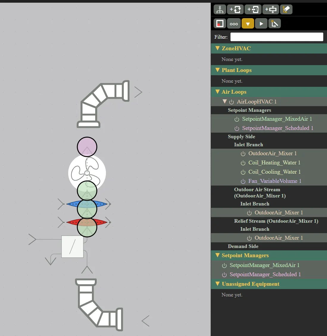
Add AirLoopHVAC, in the HVAC Outliner’s toolbar, creates a complete air loop in one undo step and selects it (The HVAC Outliner and Creating HVAC Systems):
- On the supply side, in order of flow: an
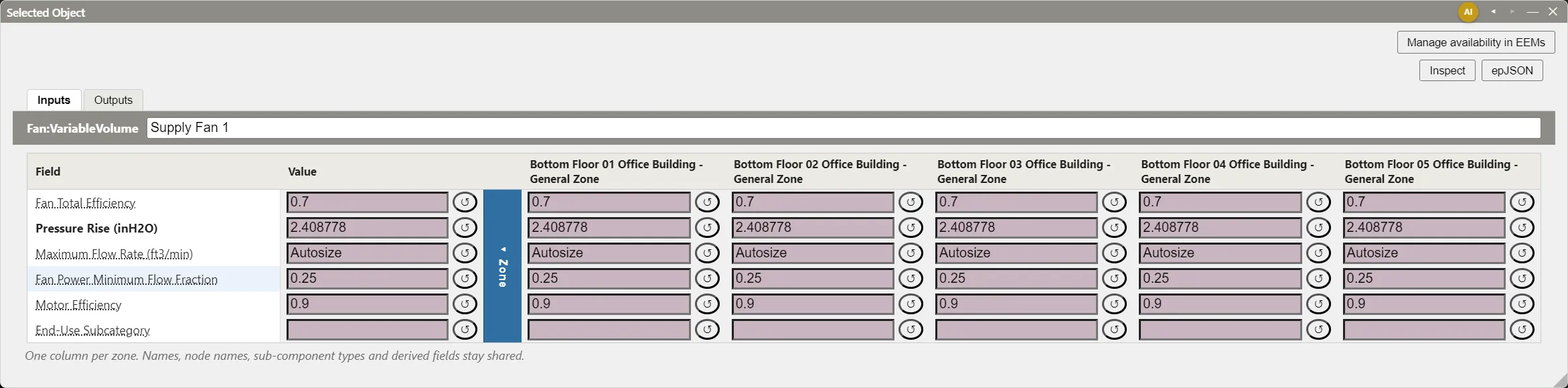
OutdoorAir:Mixer, aCoil:Heating:Water, aCoil:Cooling:Water, and aFan:VariableVolume, a draw-through fan with a pressure rise of 600 Pa (2.41 in. w.c.) and the inlet vane damper fan power coefficients (Fans and Fan Power). Its Maximum Flow Rate is blank; set it to Autosize or a design value. - The mixer’s Outdoor Air Stream and Relief Stream branches, both empty.
- A
Controller:OutdoorAirfor the mixer and aController:WaterCoilfor each coil. - A
Sizing:System(§4). - A
SetpointManager:Scheduledon the loop’s supply outlet node, and aSetpointManager:MixedAiron the mixer’s mixed air node and the air outlet nodes of the two coils. - An empty demand side. Terminals are zone equipment: you add them, connect them to the demand side, and assign them to zones (§5).
New objects are named after their type and a number (AirLoopHVAC 1, Fan_VariableVolume 1, and so on); rename them in their dialogs.
The SetpointManager:Scheduled holds the supply outlet at the Sizing:System Central Cooling Design Supply Air Temperature, 12.8°C (55.0°F), through a constant schedule created with the loop and named <loop name> Supply Air Temperature. The schedule takes the design temperature only when the loop is created; Model Validation warns when the two later differ (§8.4). The SetpointManager:MixedAir sets each coil outlet, which the coil’s controller senses, and the mixed air node, which the Controller:OutdoorAir senses once an economizer is on, to the supply outlet setpoint less the fan’s temperature rise (§8.1). The loop’s Design Supply Air Flow Rate is Autosize.
The diagram draws the loop as a vertical rail with supply air flowing up. A boundary marker at each end of the supply side marks where the loop’s two sides meet: the supply inlet at the bottom, where return air from the zones enters the supply side, and the supply outlet at the top, where supply air leaves for the demand side. The outdoor air mixer’s two streams run off to its side. The HVAC Outliner lists the loop under Air Loops (The HVAC Outliner and Creating HVAC Systems).
2.2 Supply side: one branch or parallel branches
Most air loops have one supply branch: one continuous run of components from the supply inlet to the supply outlet. Add AirLoopHVAC builds a loop this way, every air loop system in the EP3 Library is built this way, and it is the only shape that can be replicated (§10).
Add parallel supply branch, in the loop’s dialog, adds a parallel branch to the supply side. The first time, it also creates a supply splitter, a supply mixer, and an empty outlet branch, so the supply side becomes inlet branch, splitter, parallel branches, mixer, outlet branch. Connect components to the new branch with Draw Branch Connections (§3.1). Parallel supply trains are uncommon in air systems; use them only for a design that has them.
A supply side that splits into two or more separate outlets with nothing recombining them, as a dual-duct system needs, is not supported.
2.3 The outdoor air system’s streams
An OutdoorAir:Mixer sits on the supply branch by its return air and mixed air nodes. Each mixer on a loop also has two branches, created with it:
- Outdoor Air Stream — from the outside to the mixer’s outdoor air node. A preheat coil, an outdoor air fan, or the supply side of a heat exchanger goes here.
- Relief Stream — from the mixer’s relief node to the outside. A relief fan goes here.
A HeatExchanger:AirToAir:SensibleAndLatent placed on the outdoor air stream has its exhaust side connected to the same mixer’s relief air at export. EP3 writes the AirLoopHVAC:OutdoorAirSystem, its equipment list, and its controller list from the mixer, its streams, and its controllers (§7).
2.4 The demand side
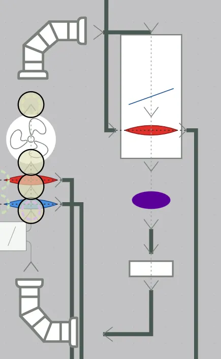
The demand side holds the loop’s terminals and plenums, one demand branch each. Each terminal connects to the supply outlet marker’s outlet node. EP3 writes the AirLoopHVAC:ZoneSplitter and AirLoopHVAC:SupplyPath that feed the terminals at export, and writes the AirLoopHVAC:ZoneMixer and AirLoopHVAC:ReturnPath from the loop’s return-air zone selection (§6.1). The zone splitter and zone mixer are not components you place: an air loop has one level of distribution, from the supply outlet to its terminals, or through a supply plenum to its terminals (§6.3).
A terminal’s air goes to the zones it serves. In the diagram, each terminal draws a marker for those zones below its air outlet node (its tooltip reads Zone(s) served by this unit), followed by a zone-return marker (Zone return). A return line runs from the zone-return marker to the supply inlet marker when the terminal’s zones return to the loop, or to the return plenum that collects them.
2.5 The air loop dialog
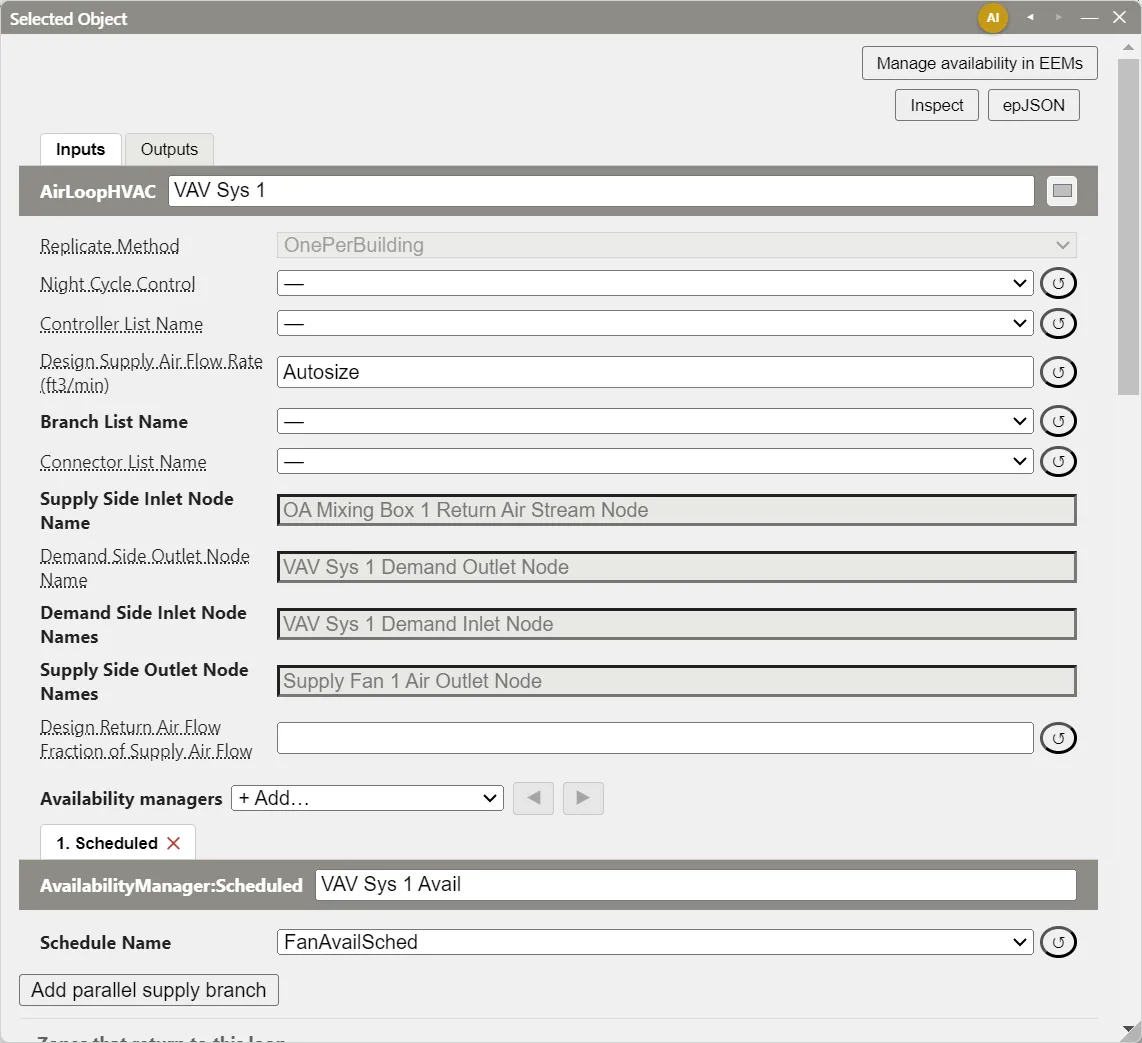
Double-click the loop’s row in the HVAC Outliner to open its dialog in the Selected Object dialog. From the top:
- Name and a color swatch, which sets the color of the loop’s connector lines and markers in the diagram.
- Replicate Method —
OnePerBuilding(the default),OnePerZone,OnePerFloor, orOnePerGroupOfZones(§10). It is disabled, showingOnePerBuilding, for a loop that cannot be replicated. - Night Cycle Control —
No(the default) orYes(§8.3). - The
AirLoopHVACfields. Design Supply Air Flow Rate accepts Autosize, which sizes it fromSizing:System. Design Return Air Flow Fraction of Supply Air Flow (1 by default) sets the return flow as a fraction of the supply flow. The node fields are read-only: EP3 fills them from the branches. - Availability managers, while Night Cycle Control is
No(§8.2). - Add parallel supply branch (§2.2).
- Zones that return to this loop (§6.1).
- The loop’s
Sizing:Systemfields (§4).
3. How Branch Connections Map onto an AirLoopHVAC
Every connection on an air loop is made with Draw Branch Connections: click a node, then the node to connect it to (The HVAC Outliner and Creating HVAC Systems). The tool marks only the nodes that can take the first pick’s component, so a connection it offers is one EP3 can export. This section covers what each kind of connection does on an air loop.
3.1 Supply-side connections
A component connected to a supply-side node is inserted on that branch at that point, in series. Connecting to the node between the heating coil and the cooling coil, for example, places the new component between them, and the components downstream move to make room. Place the supply components in the order air flows through them; Fans and Fan Power shows a draw-through branch order.
Shift+clicking a branch node adds and connects a new component in one step (The HVAC Outliner and Creating HVAC Systems), and a component placed by hand with one of its nodes close to a compatible node on a branch is connected there.
These components go on a supply branch or an outdoor air or relief stream:
- Fans:
Fan:VariableVolume,Fan:ConstantVolume,Fan:SystemModel, andFan:OnOff. The Validation dialog fails aFan:OnOffon the supply branch; EnergyPlus allows it only inside zone or unitary equipment. - Coils:
Coil:Heating:Water,Coil:Cooling:Water,Coil:Cooling:Water:DetailedGeometry,Coil:Heating:Fuel, andCoil:Heating:Electric. OutdoorAir:Mixer,HeatExchanger:AirToAir:SensibleAndLatent,Duct, theHumidifier:Steam:*humidifiers, and theEvaporativeCooler:Direct:*coolers.- Packaged components that hold their fan and coils:
CoilSystem:Cooling:DX,CoilSystem:Heating:DX, theAirLoopHVAC:Unitary*systems (includingAirLoopHVAC:UnitarySystem),Dehumidifier:Desiccant:System, andAirLoopHVAC:TerminalUnit:VariableRefrigerantFlow. Their fan and coils are drawn inside the component and edited in its dialog, one tab per sub-component.
A unitary system controls itself to a zone thermostat, so it needs no setpoint manager on its outlet (§8.1).
AirLoopHVAC:UnitaryHeatPump:WaterToAir and a water-to-air AirLoopHVAC:UnitarySystem can also use the Coil:Cooling:WaterToAirHeatPump:ParameterEstimation and Coil:Heating:WaterToAirHeatPump:ParameterEstimation coils, which model the compressor and refrigerant from manufacturer data. Their water sides connect to a condenser loop like the other water-to-air coils (Central Plant Equipment and Plant Loops). Their Refrigerant Type names a refrigerant whose property tables EnergyPlus does not have built in; the export writes EnergyPlus’s tables for it (R22, R134a, R410a and the other refrigerants EnergyPlus supplies), unless the model already has tables for that refrigerant, such as those of an imported file. ZoneHVAC:WaterToAirHeatPump does not take these coils.
3.2 Connecting terminals
To connect a terminal, click the supply outlet marker’s outlet node, then the terminal’s air inlet. The terminal goes on a demand branch of its own. These connect this way:
AirTerminal:SingleDuct:VAV:NoReheat,AirTerminal:SingleDuct:VAV:Reheat,AirTerminal:SingleDuct:VAV:HeatAndCool:Reheat,AirTerminal:SingleDuct:VAV:Reheat:VariableSpeedFan,AirTerminal:SingleDuct:ConstantVolume:Reheat,AirTerminal:SingleDuct:ConstantVolume:NoReheat,AirTerminal:SingleDuct:SeriesPIU:Reheat,AirTerminal:SingleDuct:ParallelPIU:Reheat, andAirTerminal:SingleDuct:ConstantVolume:FourPipeInduction.- A zone unit with an air terminal mixer, which takes the loop’s air at its primary air inlet (§5.4).
Connecting a terminal to the loop does not make it serve a zone. A terminal serves the zones that list it as zone equipment (§5.1).
3.3 Water coils and the plant side
A water coil sits on two branches at once: its air side on the air loop, and its water side on a plant loop’s demand side. Connect the water side with Draw Branch Connections as well: click the coil’s water inlet node, then a node or splitter port on the demand side of the hot water or chilled water loop (Central Plant Equipment and Plant Loops). The same applies to the reheat coil of a terminal. A coil whose water side is on no plant branch is exported with self-named nodes and a warning, and EnergyPlus cannot run it.
Each water coil on an air loop has a Controller:WaterCoil, edited in the coil’s dialog. Its sensor node (the coil’s air outlet) and actuator node (the coil’s water inlet) are filled in at export, and its Action is Normal for a heating coil and Reverse for a cooling coil (Controllers and Availability Managers). A terminal’s reheat coil has no controller: the terminal drives the coil’s valve.
3.4 Erasing and deleting
Erase Branch empties the branches you click or drag across, and their components move to Unassigned Equipment (The HVAC Outliner and Creating HVAC Systems). A single-branch loop’s supply side is one branch, so erasing it unassigns every supply component. To take one component off a branch, select it and press Delete: it is removed from the model, and the components on either side of it meet at a shared node.
Deleting a loop’s splitter, mixer, or boundary marker deletes the whole loop, with its branches, its Sizing:System, and its night cycle manager. The components that were on its branches move to Unassigned Equipment, and setpoint managers stop targeting its nodes.
3.5 Node names
EP3 names every node from the components around it, so node names are never typed and never go out of date. On each branch, a component’s outlet node is named <component name> <node label>, such as Main Cooling Coil Air Outlet Node, and the next component’s inlet is that same node, under the same name. Only the first component on a branch names its inlet after itself. The loop’s node fields (Supply Side Inlet Node Name, Supply Side Outlet Node Names, and the demand side’s) are the nodes of the components at the ends of its branches. Renaming a component renames its nodes.
Node fields appear read-only in each component’s dialog in complex view, and are hidden in simplified view (The EP3 Interface and Model Settings). In a replicated loop, each copy’s node names carry the copy’s prefix (§10.4).
3.6 Branches in an EEM
Branch connections can differ by EEM. A connection drawn or erased while an EEM other than Global is active is written to that EEM: the branch’s component list in that EEM replaces the list it inherits, for that EEM and the EEMs that inherit from it. A branch added in an EEM other than Global, such as a new parallel branch or a new terminal’s demand branch, exists only in that EEM and its descendants. The diagram and the outliner show the connections of the active EEM.
Because an EEM’s list replaces the inherited one, a later change to the same branch in Global does not reach an EEM that has its own list for it. Each EEM’s branches are checked at export: a component connected on two branches is an error, an empty branch is left out with a warning, and a component on no branch is left out with a warning. Energy Efficiency Measures (EEMs) covers EEMs, including a complete HVAC system as an alternative.
4. Sizing:System
4.1 Where it is
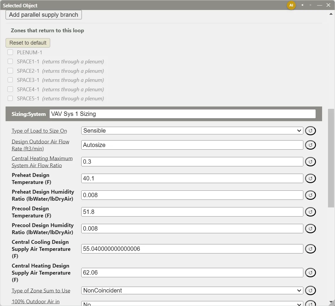
Every air loop owns one Sizing:System, created with the loop. Its fields are at the bottom of the loop’s dialog; it is not a separate object to select. It is written as <loop name> Sizing, with its AirLoop Name set to the loop. Sizing:System drives every autosized field on the loop: the fan’s flow, the coils’ capacities and, through the coils, the water flows their plant loops are sized for (§4.4).
4.2 Field set
| Field | Default | Notes |
|---|---|---|
| Type of Load to Size On | Sensible |
Sensible, Total, Latent, or VentilationRequirement (the usual choice for a dedicated outdoor air system). |
| Design Outdoor Air Flow Rate | Autosize | Autosized from the zones’ outdoor air requirements. |
| Preheat Design Temperature, Preheat Design Humidity Ratio | Required | The condition after any preheating of outdoor air. A new loop starts at Autocalculate and 0.008 (§4.2.1). |
| Precool Design Temperature, Precool Design Humidity Ratio | Required | The condition after any precooling of outdoor air. A new loop starts at Autocalculate and 0.008 (§4.2.1). |
| Central Cooling Design Supply Air Temperature | Required | A new loop starts at 12.8°C (55.0°F). Sets the cooling coil’s design leaving air temperature (§4.4). |
| Central Heating Design Supply Air Temperature | Required | A new loop starts at 40°C (104°F). |
| Type of Zone Sum to Use | NonCoincident |
NonCoincident or Coincident (§4.3). |
| 100% Outdoor Air in Cooling, 100% Outdoor Air in Heating | No |
Yes for a system with no return air, such as a dedicated outdoor air system. |
| Central Cooling Design Supply Air Humidity Ratio, Central Heating Design Supply Air Humidity Ratio | 0.008 | |
| Cooling Supply Air Flow Rate Method, Heating Supply Air Flow Rate Method | DesignDay |
Or a flow rate (Flow/System), a flow per floor area, a flow per unit of capacity, or a fraction of the autosized flow. The dialog shows the field the method uses. |
| System Outdoor Air Method | ZoneSum |
ZoneSum, Standard62.1VentilationRateProcedure, or Standard62.1SimplifiedProcedure. |
| Zone Maximum Outdoor Air Fraction | 1.0 | |
| Cooling Design Capacity Method, Heating Design Capacity Method | CoolingDesignCapacity, HeatingDesignCapacity |
Or a capacity per floor area, a fraction of the autosized capacity, or None. The capacity fields default to Autosize. |
| Central Cooling Capacity Control Method | OnOff |
OnOff, VAV, Bypass, or VT. |
| Occupant Diversity | Autosize | Used by the two Standard 62.1 methods. |
| Heating Coil Sizing Method | None |
None, CoolingCapacity, HeatingCapacity, or GreaterOfHeatingOrCooling, for a heat pump’s heating coil. |
| Maximum Heating Capacity To Cooling Capacity Sizing Ratio | 1.0 |
describes every field. A system imported from the EP3 Library or from an EnergyPlus file brings its Sizing:System values with it, and they can differ from a new loop’s starting values; review them against the design.
For a dedicated outdoor air system, set Type of Load to Size On to VentilationRequirement and both 100% Outdoor Air fields to Yes (Outdoor Air, Ventilation, and Energy Recovery).
4.2.1 Autocalculate preheat and precool
EnergyPlus requires a Preheat Design Temperature and a Precool Design Temperature on every Sizing:System, although they only matter when the outdoor air system has a preheat or precool coil. EP3 adds the value Autocalculate to both fields, and new loops start with it. On export EP3 writes the lowest outdoor dry-bulb temperature of the model’s sizing periods as the preheat temperature and the highest as the precool temperature, so a loop with no preheat or precool coil is sized as if the setting were absent. EnergyPlus always receives a number.
The sizing periods are the SizingPeriod:DesignDay, SizingPeriod:WeatherFileDays and SizingPeriod:WeatherFileConditionType objects that are on in the EEM being exported:
- A design day runs from its Maximum Dry-Bulb Temperature down to the maximum less its Daily Dry-Bulb Temperature Range. A day with a range schedule is read from the schedule’s values.
- A weather-file period is read from the weather file (the EEM’s own, otherwise the model’s): the lowest and highest hourly dry-bulb temperature between its begin and end dates, or over the dates the weather file gives for its Period Selection.
Beside Autocalculate the dialog shows the value that will be written and the sizing period it comes from, for example (-17.3 °C, from Chicago Ann Htg 99.6% Condns DB), in the units the dialog is set to. Typing a number replaces Autocalculate, and EP3 then writes that number. A loop with a coil in its outdoor air system (a preheat coil on the outdoor air stream, for instance) is sized on these temperatures, so enter the temperatures that coil is meant to condition to rather than leaving Autocalculate.
When the model has no sizing period, or a weather-file period has no readable weather file, the export reports an error naming the Sizing:System and the field. Add a design day (the Model Wizard and the weather file’s .ddy supply them) or enter a temperature.
An imported Sizing:System keeps the temperatures the file gives.
4.3 Coincident and non-coincident sizing
Type of Zone Sum to Use sets how the design airflows of the zones the loop serves (each from its Sizing:Zone, Zone-Level HVAC Equipment and Zone Sizing) combine into the system’s design airflow:
- NonCoincident adds each zone’s peak design airflow, whenever each zone peaks.
- Coincident takes the largest total of the zones’ airflows at any one time of the design day. Zones rarely all peak at once, so the coincident total is usually smaller.
Worked example (illustrative profiles). A loop serves a west zone that peaks at 500 cfm at 15:00, an east zone that peaks at 350 cfm at 10:00, and an interior zone that peaks at 420 cfm at 13:00. At three hours of the design day the zones need:
| Hour | West | East | Interior | Total |
|---|---|---|---|---|
| 10:00 | 260 cfm | 350 cfm | 380 cfm | 990 cfm |
| 13:00 | 430 cfm | 270 cfm | 420 cfm | 1,120 cfm |
| 15:00 | 500 cfm | 220 cfm | 390 cfm | 1,110 cfm |
NonCoincident sizing gives 500 + 350 + 420 = 1,270 cfm. Coincident sizing, with 13:00 as the largest total of the day, gives 1,120 cfm: 12% less fan and coil airflow. In SI units (1 cfm = 0.000472 m³/s) the zone peaks are 0.236, 0.165, and 0.198 m³/s, for a non-coincident sum of 0.599 m³/s, against a coincident peak of 1,120 × 0.000472 = 0.529 m³/s. NonCoincident is the conservative choice; Coincident credits a diversity that the building’s load profiles have to support.
4.4 Coil capacity and water flow
The system’s design airflow, the mixed-air condition on the design day, and Central Cooling Design Supply Air Temperature (or its heating counterpart) set the air temperature change a central coil is sized for. A colder cooling supply air temperature gives a larger cooling coil for the same airflow.
A water coil’s design water flow is then sized from that capacity and its plant loop’s Sizing:Plant Loop Design Temperature Difference, by Q = ṁ·cp·ΔT. The air side fixes the capacity first, so a Sizing:Plant temperature difference that does not match the coil’s design changes the water flow, and the pump sizing that follows from it, not the capacity. Central Plant Equipment and Plant Loops works the water-side calculation.
The coils’ water temperature fields are not checked against Sizing:Plant. Coil:Cooling:Water’s design water temperatures default to Autosize, and EnergyPlus takes them from the plant loop. Coil:Heating:Water’s Rated Inlet Water Temperature and Rated Outlet Water Temperature default to 82.2°C and 71.1°C (180°F and 160°F); change them when the hot water loop runs at other temperatures.
4.5 Autosizing
A field that accepts Autosize (or Autocalculate) is sized by EnergyPlus’s sizing calculation when it holds that value; the field’s tooltip lists the value it accepts. Every autosized field on an air loop depends on the loop’s Sizing:System, and through it on the Sizing:Zone of each zone the loop serves. A simulation run requests EnergyPlus’s summary reports, which include the Component Sizing Summary and HVAC Sizing Summary, so the sized values can be read in the results (Viewing and Interpreting Results).
5. Terminal Units and Zone Assignment
5.1 Which zones a loop serves
An air loop serves the zones whose zone equipment includes one of its terminals. Terminals are assigned to zones in EP3 - Select Zone Conditioning Equipment, opened with View Zone HVAC Assignments in the HVAC Outliner’s toolbar, by ZoneType or zone by zone (The Model Wizard, Zone-Level HVAC Equipment and Zone Sizing). The Model Wizard and the Import dialog make these assignments for a library system (The HVAC Outliner and Creating HVAC Systems).
The loop’s served zones drive much of this chapter: the return-air selection (§6.1), the zone list of Controller:MechanicalVentilation (§7), the control zone of the single-zone setpoint managers (§8.1), and the replicates (§10). A zone that is off in the active EEM is not served, and a zone without a thermostat is not exported with its equipment. A loop that serves no zone is exported with a warning, since EnergyPlus needs at least one.
5.2 Per-zone copies of a terminal
One terminal object can serve many zones. A terminal assigned to one zone is exported under its name; one assigned to several is exported once per zone, as <zone name> <terminal name>, each copy with a ZoneHVAC:AirDistributionUnit (<copy name> Air Dist) and an outlet of the zone splitter. The terminal is drawn once in the diagram and listed once in the outliner.
Values that differ by zone are entered in the blue drawer bar of the terminal’s dialog, which opens one column per zone it serves. A blank Design Specification Outdoor Air Object Name or availability schedule takes the zone’s, or its ZoneType’s, zone equipment default (Internal Loads, Space Types, and Zone Types).
5.3 The VAV reheat terminal
AirTerminal:SingleDuct:VAV:Reheat holds its reheat coil as a sub-component. The terminal’s dialog has a Unit tab with the terminal’s fields and a Reheat Coil Type row (Coil:Heating:Water, the default, or Coil:Heating:Electric, Coil:Heating:Fuel, or Coil:Heating:Steam), and a Reheat Coil tab with the coil’s fields. The coil’s air side is connected inside the terminal, after the damper; for a water or steam coil, connect its water side to the demand side of a hot water or steam loop (§3.3). The reheat coil type can differ by EEM, and the previous type’s inputs are kept, so switching back restores them. The other reheat and fan-powered terminals hold their coils and fans the same way.
5.4 Zone units on an air loop: AirTerminal:SingleDuct:Mixer
A zone unit can take its ventilation air from an air loop, usually a dedicated outdoor air system, through an AirTerminal:SingleDuct:Mixer. Six units support one: ZoneHVAC:FourPipeFanCoil, ZoneHVAC:PackagedTerminalAirConditioner, ZoneHVAC:PackagedTerminalHeatPump, ZoneHVAC:WaterToAirHeatPump, ZoneHVAC:UnitVentilator, and ZoneHVAC:TerminalUnit:VariableRefrigerantFlow.
On the unit’s Unit tab, set Air Terminal Mixer Type to AirTerminal:SingleDuct:Mixer (None removes it). The mixer takes the place of the unit’s outdoor air mixer, and its Mixer Connection Type sets where the loop’s primary air joins the unit’s recirculated air:
InletSide(the default): the two streams mix before the unit conditions them.SupplySide: the unit conditions the recirculated air, and the primary air joins it on the way to the zone.
The unit then has a primary air inlet node; connect it to the loop’s supply outlet like a terminal (§3.2). The mixer is part of the unit, so it is not listed as separate zone equipment.
6. Return Air and Plenums
6.1 Zones that return to this loop
Supply air reaches a zone through a terminal, and return air leaves through the zone’s return node, so which zones return air to a loop is a setting of the loop. Zones that return to this loop, in the loop’s dialog, lists every zone in the model:
- A zone the loop serves is checked by default. Returning zones are shown in bold.
- A zone the loop does not serve is greyed out and cannot be checked.
- A zone whose return goes to a return plenum on this loop is greyed out and marked (returns through a plenum).
Clear a served zone to send none of its return air to this loop, as for a zone that exhausts all of its air. Reset to default returns the list to every served zone that no plenum claims. The selection can differ by EEM. A loop with no returning zones is exported without a zone mixer or return path, with a warning.
6.2 Return plenums
An AirLoopHVAC:ReturnPlenum models a ceiling plenum that collects the return air of the zones below it. Add it from the Air Loop Equipment heading of the HVAC Components dialog and connect it to the supply inlet marker’s inlet node. In its dialog:
- Plenum Zone lists only zones without a thermostat, since EnergyPlus requires a plenum zone to be unconditioned. Model the plenum space as a zone of its own first.
- Select zones to connect to Plenum: checks the zones whose return air goes into the plenum. Connect All checks every zone, and Select None clears the list.
The plenum’s zones are taken out of the loop’s return list (§6.1). A return plenum that no returning zone of the loop feeds is left out of the export, with a warning.
6.3 Supply plenums
An AirLoopHVAC:SupplyPlenum models a plenum that distributes supply air, such as an underfloor plenum. Connect it from the supply outlet marker’s outlet node, like a terminal. Its Plenum Zone follows the same rule as a return plenum’s. Select terminals fed by this Plenum: checks the terminals on the loop that take their air from the plenum; the others stay on the zone splitter. The export writes the zone splitter, the plenum, and the plenum’s terminals in that order. A supply plenum that feeds no terminal is left out, with a warning.
A loop with either kind of plenum cannot be replicated.
7. The Outdoor Air System
An OutdoorAir:Mixer mixes return air with outdoor air early on the supply branch, ahead of the main coils, and its two streams hold any equipment that treats the outdoor and relief air (§2.3). Air-Side System Fundamentals covers the mixed-air path.
The mixer’s controls are edited in the mixer’s dialog while it sits on an air loop:
Controller:OutdoorAir— the minimum and maximum outdoor air flow and the economizer. Its node fields are filled in at export.- Use Controller:MechanicalVentilation? —
Yesgives the mixer aController:MechanicalVentilation, owned by the mixer. Its fields appear below theController:OutdoorAirfields, followed by a Zones table with one row per zone the loop serves; each row picks the zone’sDesignSpecification:OutdoorAir(by default the one itsSizing:Zonenames) andDesignSpecification:ZoneAirDistribution. Switching it back toNokeeps the controller and its values, unused. The switch can differ by EEM and by replicate.
Outdoor Air, Ventilation, and Energy Recovery covers these controllers, demand-controlled ventilation, economizers, and energy recovery.
8. Setpoint Managers and Availability Managers
8.1 Setpoint managers
EnergyPlus controls supply-side equipment with node setpoints. A setpoint manager calculates a setpoint each time step, from a schedule, the zones’ needs, the outdoor air temperature, or another node, and places it on one or more nodes; the equipment upstream of a node works to reach it. A Coil:Cooling:Water, for example, modulates its water flow through its Controller:WaterCoil to bring its air outlet node to the setpoint there. Every water, fuel, or electric coil that stands alone on an air loop branch needs a setpoint at its air outlet node. A packaged component such as AirLoopHVAC:UnitarySystem controls itself to a zone thermostat and needs none.
Adding one. Add a setpoint manager from the Setpoint Managers heading of the HVAC Components dialog. It has no box in the diagram: it is listed in the outliner’s Setpoint Managers section and under each loop it controls, and it opens in the Selected Object dialog when selected (double-clicking its outliner row opens it in the main object dialog). In its Setpoints section, each row (Setpoint 1, Setpoint 2, and so on) picks an object and one of its nodes; + Add adds the row, and × removes one. The loop is one of the objects: choosing the loop’s Supply Side Outlet Node Names keeps the setpoint on the supply outlet even if the last component on the branch is replaced. A manager with more than one setpoint is written with a NodeList.
In the diagram, each setpoint is a translucent circle on its node, in the manager’s color. Hovering over a circle names the manager, and clicking it selects the manager. Hovering over the manager’s outliner row, or over its Setpoints rows, enlarges its circles.
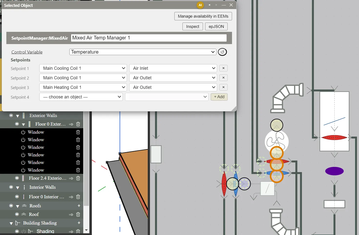
Types for air loops. EP3 supports every SetpointManager:* type. These are the ones used on air loops:
SetpointManager:Scheduledsets a node to a schedule’s value. On an air loop it usually holds the supply outlet at the design supply air temperature, or at a schedule that resets it by season. It works on plant loops too.SetpointManager:OutdoorAirResetresets a setpoint linearly with the outdoor air temperature, between Setpoint at Outdoor Low Temperature at Outdoor Low Temperature and Setpoint at Outdoor High Temperature at Outdoor High Temperature.SetpointManager:MixedAirsets nodes upstream of the supply fan from the setpoint downstream of it, lowered by the fan’s temperature rise (worked below). Its reference setpoint node is the loop’s supply outlet, and its fan and cooling coil nodes are those of the first fan and the first cooling water coil on the supply branch, all filled in at export unless you pick nodes for Reference node, Fan inlet node, Fan outlet node, Cooling coil inlet node or Cooling coil outlet node (use the dropdowns, or the crosshair button to click a node in the diagram). The cooling coil nodes are optional in EnergyPlus: the Cooling coil nodes checkbox turns them on or off for each EEM (↺ makes the EEM inherit again); it is off unless you turn it on, or the manager was imported from a file that names coil nodes. On, the manager also keeps the coil outlet from falling below 7.2°C (45°F) during economizer operation, which protects the coil from freezing; off, it only subtracts the fan’s temperature rise. Use it for each coil outlet upstream of the fan, and for the mixer’s mixed air node, which the economizer controls to.SetpointManager:SingleZone:Reheat,:Heating, and:Cooling, and the:OneStageand:Humiditysingle-zone types, control the supply air to one zone’s needs. The temperature managers have a Control zone picker listing the zones the loop serves; left blank, or set to a zone a replicate does not serve, the control zone is the first zone the loop (or the replicate) serves. The:Humiditymanagers control to the zone with the humidistat. EP3 fills in the control zone’s nodes from its terminal at export. They suit a loop that serves one zone, or one replicatedOnePerZone.SetpointManager:Warmest,:Coldest,:WarmestTemperatureFlow,:ReturnAirBypassFlow, and the:MultiZone:*types respond to every zone the loop serves.Warmestresets a VAV system’s supply air temperature up to what the zone with the largest cooling demand needs. Their HVAC Air Loop Name is filled in at export.SetpointManager:OutdoorAirPretreatsets a node on the outdoor air stream, with its mixer nodes filled in at export.SetpointManager:FollowSystemNodeTemperatureand theSetpointManager:SystemNodeReset:*types have a Reference node picker below their Setpoints.
A setpoint manager that targets an air loop is written once per replicate of the loop, named <replicate name> <manager name>, with that replicate’s node names (§10).
Worked example: the fan’s temperature rise. A draw-through Fan:VariableVolume with a pressure rise ΔP of 600 Pa, a Fan Total Efficiency η of 0.7 (the default), and a Motor In Airstream Fraction of 1 (the default) adds all of its power to the air. Per unit of airflow its power is ΔP/η, so its temperature rise is
ΔT = ΔP / (η · ρ · cp) = 600 / (0.7 × 1.2 kg/m³ × 1006 J/kg·K) = 600 / 845 = 0.71 K
. With the supply outlet held at 12.8°C, SetpointManager:MixedAir sets the cooling coil’s outlet to 12.8 − 0.71 = 12.09°C, and the air leaves the fan at 12.8°C. In IP units, 600 Pa is 2.41 in. w.c., and a fan of efficiency 1 raises air 0.3715°F per in. w.c., so the rise is 2.41 × 0.3715 / 0.7 = 1.28°F (0.71 K × 1.8): a 55.0°F supply setpoint puts the coil outlet at 53.8°F. Without the adjustment, the fan’s heat would leave the supply air about 0.7 K (1.3°F) above the setpoint the coil holds.
Output at setpoint nodes. For every node a setpoint manager sets, the export requests the node’s temperature, mass flow rate, and setpoint (and its humidity ratio, for a humidity manager) as Output:Variable objects at the model’s reporting frequency, so the node’s operation can be checked after a run without further setup (§9).
8.2 Availability managers
An air loop’s availability managers decide when its fans may run, in addition to the fans’ availability schedules. They are listed in the Availability managers section of the loop’s dialog while Night Cycle Control is No. + Add… adds a manager of the chosen type at the end of the list; each manager has a tab with its fields, the tab’s ✕ removes it, and the arrow buttons move it earlier or later in the list. With no managers, the loop runs whenever its fans’ schedules allow. EP3 writes the AvailabilityManagerAssignmentList and the loop’s Availability Manager List Name at export, one list per replicate.
The fans’ schedules set the hours the loop normally runs, and the managers adjust them: a night cycle or an optimum start can start a loop that is scheduled off, but cannot stop one that is scheduled on, so a loop whose fans are on Always On runs all year (Controllers and Availability Managers). The air loop systems in the EP3 Library run their fans on the office HVAC operation schedule FanAvailSched (weekdays 6:00 to 22:00, Saturdays 6:00 to 18:00), with an AvailabilityManager:OptimumStart over the zones the loop serves and an AvailabilityManager:NightCycle on the same schedule.
The fans can follow the zones’ supply air fan operating mode schedules instead of one named schedule: choose Follow ZoneHVAC Fan Operating Mode Schedules at the top of their schedule dropdown. Each copy of a replicated loop then runs whenever any of its own zones has its fan operating mode schedule on, using the shared schedule or a generated union of the zones’ schedules. A night cycle or an optimum start on an air loop has no Fan Schedule Name of its own: it always uses the supply fan’s schedule (Controllers and Availability Managers).
A manager that needs a control zone defaults to the first zone the loop (or the replicate) serves, and can be set to any served zone. The zone is fixed instead when a unitary system or a single-zone setpoint manager already controls the loop to one zone; the dialog says so. A manager that reads a node, such as AvailabilityManager:LowTemperatureTurnOff, picks its sensor node from the loop’s components or the outdoor air. Controllers and Availability Managers covers each manager type.
8.3 Night Cycle Control
Setting Night Cycle Control to Yes gives the loop a built-in AvailabilityManager:NightCycle, which cycles the loop’s fans on to hold the zone thermostats while the system is otherwise scheduled off. A Night Cycle tab appears beside the Air Loop tab of the loop’s dialog, with the manager’s fields, starting at:
- Control Type
CycleOnAnyand Thermostat Tolerance 0.2°C (0.36°F). - Applicability Schedule Name: Always On.
- Fan Schedule Name: not a field on this tab. A read-only line shows the availability schedule of the loop’s supply fan (Always On if the fan has none), per replicate when the fan’s schedule differs by replicate, and the export writes that schedule. When the supply fan is set to Follow ZoneHVAC Fan Operating Mode Schedules, the line shows what that resolves to.
The manager is named and written with the loop, in an AvailabilityManagerAssignmentList. Night Cycle Control and the Availability managers list are alternatives: with Night Cycle Control Yes the list is hidden. To combine a night cycle with other managers, set Night Cycle Control to No and add an AvailabilityManager:NightCycle to the list. The ✕ on the Night Cycle tab sets Night Cycle Control back to No and keeps the manager’s values for the next time it is switched on.
8.4 Checking your work
The Validation dialog has a card for each air loop under Air Loops, with two checks (Model Troubleshooting and Quality Assurance):
- Setpoint Manager Coverage lists the loop’s setpoint managers by family. It fails when no setpoint manager controls the loop’s supply outlet, and warns when a setpoint does not match the loop’s
Sizing:Systemdesign supply air temperatures, such as a 15°C (59°F) supply setpoint on a loop sized for 12.8°C (55.0°F). It fails when no setpoint manager controls the air outlet of a water coil, which the coil’sController:WaterCoilsenses, or of a fuel or electric heating coil, or the mixed air node of a mixer whoseController:OutdoorAirhas an economizer. It fails aSetpointManager:MixedAirwhose reference node no other setpoint manager controls, or whose fan nodes do not belong to one fan. A node set by more than one manager is a warning, or a failure when a humidity manager or aSetpointManager:Scheduledis one of them. - Supply Branch Fan Type fails a
Fan:OnOffon the supply branch; the section appears only when there is one.
9. Node Data: NodeReport
A NodeReport requests output at chosen nodes: one Node Report Variable (System Node Temperature by default) at a Reporting Frequency (Hourly by default), optionally only while a Schedule Name is non-zero. Add it in the main object dialog, in Column 1’s Output Reporting group. In its Nodes section, pick nodes from the lists, or click the crosshair button beside the lists, which marks every node in the HVAC diagram: click a node to add or remove it, where several nodes share a spot a short list opens. Press Space to keep the picks and return to Select, or Escape to drop them and bring back the previous tool. Each node can also carry an EnergyManagementSystem:Sensor name. A NodeReport’s nodes are drawn with dashed rings in the diagram. The export writes one Output:Variable per node, and per replicate of a replicated loop.
Setpoint nodes already report their temperature, flow, and setpoint (§8.1); a NodeReport covers the other nodes. Viewing and Interpreting Results covers reading node data.
10. Replicating an AirLoopHVAC
10.1 Replicate methods
One air loop in the model can stand for many identical air loops in the building: a packaged unit on every zone, or an air handler on every floor. Replicate Method, in the loop’s dialog, sets how many copies the export writes:
OnePerBuilding(the default) — one loop.OnePerZone— one loop for each zone the loop serves.OnePerFloor— one loop for each floor that holds a zone the loop serves, serving that floor’s zones.OnePerGroupOfZones— one loop for eachGroupOfZonesthat holds a zone the loop serves (§10.5).
The loop, its branches, and its components are drawn and edited once. At export, EP3 writes each copy with its name, node names, components, controllers, Sizing:System, zone splitter and mixer, availability managers, and setpoint managers, and writes the water side of each coil as one plant demand branch per copy. The zones the copies serve come from the terminal’s zone assignments (§5.1); the method divides them among the copies. The method can differ by EEM.
10.2 Which loops can be replicated
A loop can be replicated when it has one supply branch, exactly one terminal on its demand side, and no plenum. That one terminal serves every zone the copies divide among themselves. A loop that does not meet these conditions exports as one loop: its Replicate Method is disabled and shows OnePerBuilding, and if another method is stored, a note in the dialog says why it does not apply (for example, that the loop does not have exactly one air terminal on its demand side). The stored method applies again once the loop can be replicated. The default loop has no terminal, so its Replicate Method is disabled until one is connected.
A method that gives only one copy, such as OnePerFloor on a one-story building, writes the loop under its name, with no prefix and no replicate columns.
10.3 Values that differ by replicate
When a loop has two or more replicates, the dialogs of the loop and of everything on it show one column per replicate in the blue drawer bar, headed with the replicate’s name and labeled Zone, Floor, or Group of zones. This covers the supply components and their sub-components, the mixer’s and coils’ controllers, Sizing:System, the Night Cycle tab, the setpoint managers that target the loop, and the terminal. A value entered in a column applies to that copy, and a blank column takes the shared value. In an EEM, a replicate’s value set in a parent EEM is inherited until the EEM changes it.
These stay shared and read-only in the replicate columns: names, node names, sub-component types, Include in EEM, Replicate Method, Night Cycle Control, the loop color, and the flow-rate method and number-of-speeds fields. A terminal under OnePerFloor or OnePerGroupOfZones shows floor or group columns, and a value in its zone columns (§5.2) takes precedence over its replicate’s value.
Values entered for replicates that no longer exist, after the method changes or a zone moves to another floor or group, are kept and listed under Orphaned per-replicate values. They return if the method is switched back, and Clear orphaned values removes them.
10.4 Names
Each copy’s objects are named <replicate name> <object name>, where the replicate name is the zone’s, the floor’s, or the group’s: a OnePerFloor loop named VAV-1 on a floor named Floor 2 is written as Floor 2 VAV-1, and its fan, coils, nodes, branches, and node lists carry the same prefix. The names are computed at export; the exported epJSON file shows each copy.
10.5 Groups of zones
OnePerGroupOfZones uses GroupOfZones objects. Create one in the main object dialog: in Column 1’s Thermal Zones and Surfaces group, select GroupOfZones, click Add Object, and add zones to its Zone Name list. A zone can be in only one group: adding it to a group removes it from any other. A GroupOfZones writes nothing to EnergyPlus; it only divides zones among a loop’s copies. A served zone in no group gets no copy, and its terminal is left out of the export, with a warning.
11. Worked Example: A VAV Air Loop from the Default Loop
This example builds a VAV air loop with reheat that serves every zone of a model with a hot water loop and a chilled water loop (Central Plant Equipment and Plant Loops). The AirLoopHVAC Water Coils VAV Reheat template in the EP3 Library is a finished system of this kind; the steps show what it is made of.
- Add the loop. Click Add AirLoopHVAC in the HVAC Outliner, and rename the loop
VAV-1in its dialog. - Connect the coils’ water sides. Turn on Draw Branch Connections. Click the heating coil’s water inlet node, then a port on the hot water loop’s demand side. Click the cooling coil’s water inlet node, then a port on the chilled water loop’s demand side.
- Check the supply air temperature. The loop’s
SetpointManager:Scheduledholds the supply outlet at 12.8°C (55.0°F) through the schedule created with the loop. For a different supply temperature, change the schedule’s value (Schedules) and theSizing:Systemdesign temperature together. - Check the mixed air setpoints. The loop’s
SetpointManager:MixedAirsets the mixer’s mixed air node, which the economizer controls to, and the Air Outlet node of each coil to 12.8°C less the fan’s rise: 12.09°C (53.8°F) for the default fan (§8.1). - Add the terminal. From the HVAC Components dialog’s ZoneHVAC heading, add an
AirTerminal:SingleDuct:VAV:Reheatand place it beside the loop. With Draw Branch Connections on, click the supply outlet marker’s outlet node, then the terminal’s air inlet. Then click the reheat coil’s water inlet and a port on the hot water loop’s demand side. - Assign the terminal to the zones. Click View Zone HVAC Assignments and add the terminal to each
ZoneType, or each zone, the loop serves. The terminal is exported once per zone (§5.2). - Check the return air. In the loop’s dialog, Zones that return to this loop shows every served zone in bold.
- Check
Sizing:System. Central Cooling Design Supply Air Temperature is 12.8°C (55.0°F), matching the setpoint. Set Central Heating Design Supply Air Temperature to the central heating coil’s design leaving temperature; in a VAV reheat system the central coil tempers the mixed air and the reheat coils heat the zones, so the library template uses 16.7°C (62.1°F). Set the loop’s Design Supply Air Flow Rate to Autosize. - Choose the replication. For one air handler serving the building, leave Replicate Method at
OnePerBuilding. For one air handler per floor, chooseOnePerFloor: the loop has one supply branch and one terminal, so it can be replicated. - Add a night cycle if the fans are scheduled off at night: set Night Cycle Control to
Yes. - Validate and simulate. Click Validate in the top toolbar: under Air Loops, the loop’s card lists the two setpoint managers, with no failure for the supply outlet and no mismatch against
Sizing:System. Then simulate (Running Simulations) and check the setpoint nodes’ temperatures in the results.
12. Where to Go Next
- Zone-Level HVAC Equipment and Zone Sizing — terminals as zone equipment, equipment order, and
Sizing:Zone. - Central Plant Equipment and Plant Loops — the plant loops that serve water coils,
Sizing:Plant, and plant setpoint managers. - Fans and Fan Power — fan types, branch order, and fan power inputs.
- Controllers and Availability Managers —
Controller:WaterCoiland each availability manager type. - Outdoor Air, Ventilation, and Energy Recovery — the outdoor air system, economizers, demand-controlled ventilation, and dedicated outdoor air systems.
- Energy Efficiency Measures (EEMs) — EEMs, including branch connections that differ by EEM.
- Model Troubleshooting and Quality Assurance — the Validation dialog and diagnosing unmet hours.
This handbook is also built into EP3 (Help), where its EnergyPlus links open the EnergyPlus Reference. Technical specifications · Book a demo