Outdoor Air, Ventilation, and Energy Recovery
1. Overview
This chapter covers where a model’s ventilation requirement is entered (§2), how an air loop delivers it (§3), how ventilation can follow occupancy (§4), how a dedicated outdoor air system (DOAS) is built in EP3 (§5), and how a heat exchanger recovers energy from relief air (§6).
The outdoor air system’s streams are covered in Air Loops, Branches, and Nodes, economizer types and their psychrometrics in Air-Side System Fundamentals, the outdoor air fields of Sizing:Zone in Zone-Level HVAC Equipment and Zone Sizing, and infiltration and natural ventilation in Infiltration, Natural Ventilation and Airflow Networks.
2. Outdoor air requirements
2.1 DesignSpecification:OutdoorAir
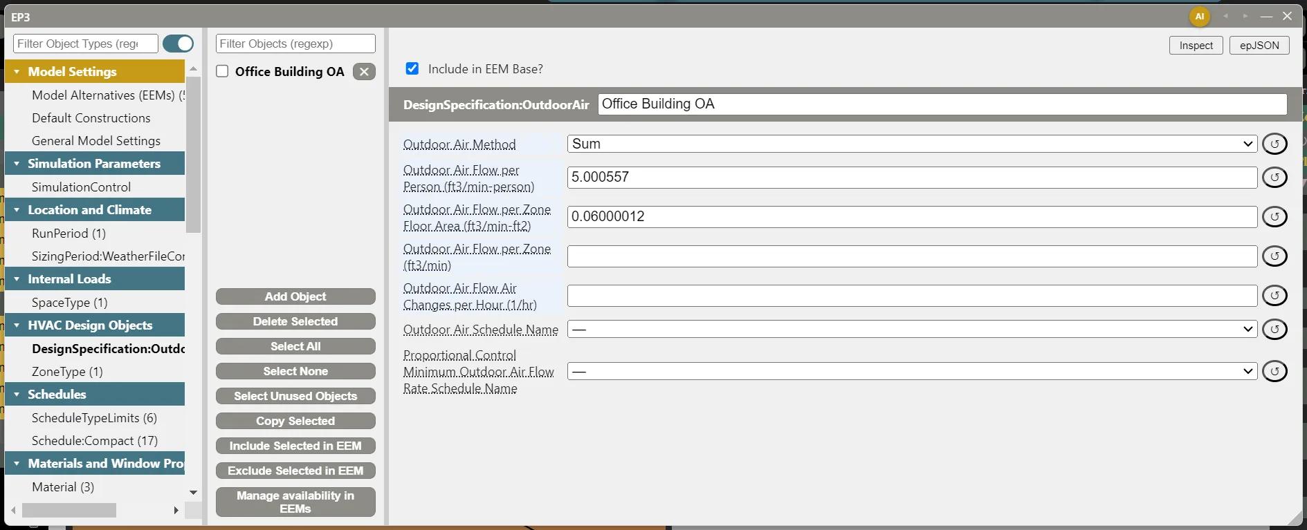
A DesignSpecification:OutdoorAir, under HVAC Design Objects in the main object dialog, states a zone’s ventilation requirement. Outdoor Air Method sets the calculation, and the dialog shows only the flow fields the method uses:
| Outdoor Air Method | Zone outdoor air flow |
|---|---|
Flow/Person (the default) |
Outdoor Air Flow per Person × occupants |
Flow/Area |
Outdoor Air Flow per Zone Floor Area × floor area |
Flow/Zone |
Outdoor Air Flow per Zone |
AirChanges/Hour |
Outdoor Air Flow Air Changes per Hour × volume ÷ 3,600 |
Sum / Maximum |
The four flows added / the largest of them |
The IndoorAirQualityProcedure and ProportionalControl methods use no flow field and pair with the Controller:MechanicalVentilation methods of the same names (§4.1). Outdoor Air Flow per Person defaults to 0.00944 m³/s (20 cfm) per person, the other rates to 0. Outdoor Air Schedule Name multiplies the flow by a 0–1 value.
Occupants come from the zone’s People (Internal Loads, Space Types, and Zone Types): the design number for sizing, the number times the occupancy schedule where a calculation uses current occupancy (§4). For a zone whose spaces need different rates, a DesignSpecification:OutdoorAir:SpaceList (also under HVAC Design Objects) names a DesignSpecification:OutdoorAir per space and can be used wherever a DesignSpecification:OutdoorAir can.
2.2 Where the requirement is named
Three separate references carry the requirement, each read for a different purpose:
| Reference | Where it is set | What reads it |
|---|---|---|
Sizing:Zone Design Specification Outdoor Air Object Name |
The ZoneType’s Sizing:Zone tab (Internal Loads, Space Types, and Zone Types) |
Sizing: the zone’s design outdoor air, summed into Sizing:System Design Outdoor Air Flow Rate (§3.2). Also the default for the Controller:MechanicalVentilation zone rows. |
| The equipment’s Design Specification Outdoor Air Object Name | An air terminal, a zone unit’s air terminal mixer, or ZoneHVAC:IdealLoadsAirSystem; blank, the Zone’s, then the ZoneType’s ZoneHVAC Design Specification Outdoor Air Object Name |
The terminal’s outdoor air control each time step (§4.2). |
A Controller:MechanicalVentilation zone row |
The Zones table in the outdoor air mixer’s dialog | The air loop’s outdoor air in operation (§4.1). |
The EP3 Library’s internal load templates give each ZoneType’s Sizing:Zone an object named after the template (Office Building OA for Office Building - General), so a Wizard model is sized with ventilation air. They leave the ZoneType’s ZoneHVAC Design Specification Outdoor Air Object Name blank, so terminals have no outdoor air control until it, the Zone’s, or the terminal’s field is set (Internal Loads, Space Types, and Zone Types). Each zone’s column in the terminal’s dialog shows what it inherits (Zone-Level HVAC Equipment and Zone Sizing).
Packaged zone units set outdoor air as flow rates on the unit: Maximum Outdoor Air Flow Rate and Outdoor Air Schedule Name on a fan coil; Cooling Outdoor Air Flow Rate, Heating Outdoor Air Flow Rate, and No Load Outdoor Air Flow Rate on the packaged terminal units.
2.3 Worked example: an office zone’s outdoor air
The template’s Office Building OA uses Sum with 0.00236 m³/s per person (5 cfm per person) and 0.0003048 m³/s per m² (0.06 cfm/ft²), the ASHRAE Standard 62.1 office rates. Its People sets 25.6 m² (275.6 ft²) per person, the whole-building office density of the ASHRAE Standard 90.1 User’s Manual (Table G-D). For a 92.90 m² (1,000 ft²) zone:
- Occupants: 92.90 ÷ 25.6 = 3.629
- People part: 0.00236 × 3.629 = 0.00856 m³/s; area part: 0.0003048 × 92.90 = 0.02832 m³/s
- Design outdoor air: 0.00856 + 0.02832 = 0.03688 m³/s (36.9 L/s)
Check in IP units. 5 × 3.629 + 0.06 × 1,000 = 18.1 + 60.0 = 78.1 cfm, and 78.1 × 0.4719 = 36.9 L/s. This is the Standard 62.1 breathing-zone flow Vbz = Rp·Pz + Ra·Az; the Ventilation Rate Procedure divides it by the zone air distribution effectiveness (1.0 by default).
3. Outdoor air on an air loop
3.1 The outdoor air system
An OutdoorAir:Mixer on the supply branch mixes return air with outdoor air; its Outdoor Air Stream and Relief Stream hold preheat coils, outdoor air and relief fans, and heat exchangers (Air Loops, Branches, and Nodes, Fans and Fan Power). EP3 writes the AirLoopHVAC:OutdoorAirSystem, its equipment list, and its controller list at export, and declares the first node of the outdoor air stream an outdoor air node.
The mixer’s Controller:OutdoorAir is created when the mixer is placed on a loop. Its fields follow the mixer’s in the mixer’s dialog, without the node fields, which are filled in at export (Controllers and Availability Managers).
3.2 Minimum and maximum outdoor air
- Minimum Outdoor Air Flow Rate and Maximum Outdoor Air Flow Rate start at Autosize: the minimum takes
Sizing:SystemDesign Outdoor Air Flow Rate, autosized from the zones’Sizing:Zoneoutdoor air, and the maximum takes the loop’s design supply airflow. - Minimum Limit Type
ProportionalMinimum(the default) scales the minimum with supply airflow, so a VAV loop at part flow takes less outdoor air;FixedMinimumholds the flow. - Minimum Outdoor Air Schedule Name multiplies the minimum. A schedule at 0 outside occupied hours keeps the damper shut during a night cycle or morning warm-up; blank applies the full minimum whenever the loop runs.
- Minimum Fraction of Outdoor Air Schedule Name and Maximum Fraction of Outdoor Air Schedule Name bound the outdoor air as a fraction of the mixed airflow; a minimum fraction of 1 gives 100% outdoor air.
3.3 Economizers
To set up an economizer (Air-Side System Fundamentals compares the types and works a dry-bulb and an enthalpy decision):
- Choose Economizer Control Type and its limits. Economizer Minimum Limit Dry-Bulb Temperature, shown for every type, holds the minimum below that outdoor temperature.
- Check the mixed air node’s setpoint. The economizer modulates the damper to hold the mixer’s mixed air node at its setpoint. A new loop’s
SetpointManager:MixedAirsets it; on a loop built otherwise, add a Setpoints row for the mixer’s Mixed Air Node (Air Loops, Branches, and Nodes). The Validation dialog fails an economizer whose mixed air node has no setpoint (Air Loops, Branches, and Nodes). - Set Lockout Type.
NoLockout(the default) lets the economizer run with mechanical cooling.LockoutWithHeatingholds the minimum while the loop heats;LockoutWithCompressoralso while a DX compressor runs.
Economizer Control Action Type ModulateFlow (the default) raises outdoor air toward the maximum; MinimumFlowWithBypass holds the minimum and bypasses heat recovery instead (§6.3). High Humidity Control Yes shows Humidistat Control Zone Name and High Humidity Outdoor Air Flow Ratio: while that zone is above its humidistat setpoint, outdoor air is the maximum times the ratio. The zone needs a ZoneControl:Humidistat (Controllers and Availability Managers).
4. Demand-controlled ventilation
Demand-controlled ventilation (DCV) cuts outdoor air below the design rate when fewer people are present. EP3 models it on an air loop with Controller:MechanicalVentilation, and per zone through terminal and ideal loads fields.
4.1 Controller:MechanicalVentilation
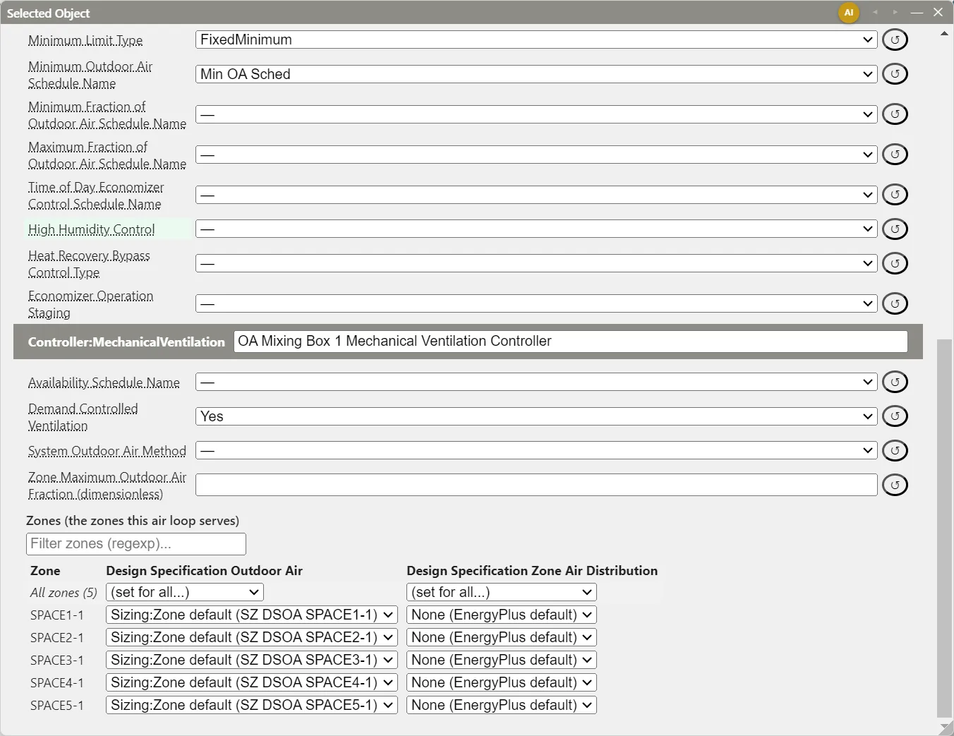
The mixer’s Use Controller:MechanicalVentilation? row (No by default) appears while the mixer is on an air loop. Yes creates the controller and shows its fields below the Controller:OutdoorAir’s; No keeps its values, unused. The switch can differ by EEM and by replicate.
| Field | Default | Effect |
|---|---|---|
| Availability Schedule Name | Blank (always on) | At 0, no ventilation is requested. |
| Demand Controlled Ventilation | No |
Yes uses current occupants for the per-person rate; No, design occupants. |
| System Outdoor Air Method | Standard62.1VentilationRateProcedure |
ZoneSum adds the zone flows. The Ventilation Rate Procedure applies air distribution effectiveness and system ventilation efficiency; ...WithLimit caps it at the design flow. IndoorAirQualityProcedure and the ProportionalControl methods control to CO2 or another contaminant. |
| Zone Maximum Outdoor Air Fraction | 1.0 | A VAV zone needing a larger outdoor air fraction gets more supply air instead. |
Sizing:System has a field of the same name for the design calculation (Air Loops, Branches, and Nodes); set both.
The Zones table lists each zone the loop serves, with a Design Specification Outdoor Air and a Design Specification Zone Air Distribution select. Sizing:Zone default, the default, uses the object the zone’s Sizing:Zone names; None leaves the air distribution blank (effectiveness 1.0). Filter zones (regexp)… narrows the rows, and the All zones row sets every row shown. At export the controller lists the zones each copy of the loop serves, so it follows zone assignment. A DesignSpecification:ZoneAirDistribution (HVAC Design Objects) sets the cooling and heating air distribution effectiveness (1.0 by default) and the Ventilation Rate Procedure’s Zone Secondary Recirculation Fraction and Minimum Zone Ventilation Efficiency.
The minimum still applies. The loop takes the larger of the Controller:OutdoorAir minimum (times its schedule) and the mechanical ventilation flow. An autosized minimum equals the design outdoor air, so DCV never reduces the flow below it: set Minimum Outdoor Air Flow Rate to 0, or to the flow needed at zero occupancy. Setting Demand Controlled Ventilation to Yes while the minimum is Autosize shows the notice EP3 - Demand Controlled Ventilation above the controller’s fields: Set Minimum Outdoor Air Flow Rate to 0 (recommended) sets it in the active EEM (for one replicate, when set in a replicate’s column), and Keep current value or × leaves it.
4.2 Terminals and ideal loads
A terminal with a Design Specification Outdoor Air Object Name raises its airflow, up to its maximum, until it delivers the zone’s outdoor air at the loop’s current outdoor air fraction; without one it follows the zone load only. The loop’s controller sets how much outdoor air the loop draws, and the terminals how much of it each zone gets.
AirTerminal:SingleDuct:VAV:Reheatand:VAV:NoReheatuse current occupants for the per-person part.AirTerminal:SingleDuct:ConstantVolume:NoReheatandAirTerminal:SingleDuct:Mixerhave Per Person Ventilation Rate Mode,CurrentOccupancy(the default) orDesignOccupancy. The mixer is a sub-component of a zone unit; its Design Specification Outdoor Air Object Name takes theZoneandZoneTypedefault like a terminal’s (§2.2).ZoneHVAC:IdealLoadsAirSystemhas Demand Controlled Ventilation Type (None,OccupancySchedule,CO2Setpoint), Outdoor Air Economizer Type, and Heat Recovery Type, for a load study before a system is chosen (Zone-Level HVAC Equipment and Zone Sizing).
4.3 Worked example: ventilation at part occupancy
For the §2.3 zone in an hour when the occupancy schedule is 0.5, with DCV on, the per-person part uses 5.50 occupants:
- SI: 0.00236 × 5.50 + 0.02832 = 0.01297 + 0.02832 = 0.04129 m³/s (41.3 L/s)
- IP: 5 × 5.50 + 60.0 = 87.5 cfm, and 87.5 × 0.4719 = 41.3 L/s
That hour saves 27.5 of 115 cfm (24%). The area part is fixed, so DCV can save at most the people part, 55 of 115 cfm (48%), and only with the Controller:OutdoorAir minimum below the DCV flow.
5. Dedicated outdoor air systems
A DOAS conditions outdoor air in a separate air loop and delivers it to the zones, where zone equipment meets the load. In EP3 a DOAS is an AirLoopHVAC sized and controlled for 100% outdoor air.
5.1 A DOAS air loop
The EP3 Library’s DOAS with water coils, in the Model Wizard or under Import > Library templates (The HVAC Outliner and Creating HVAC Systems), has:
- a
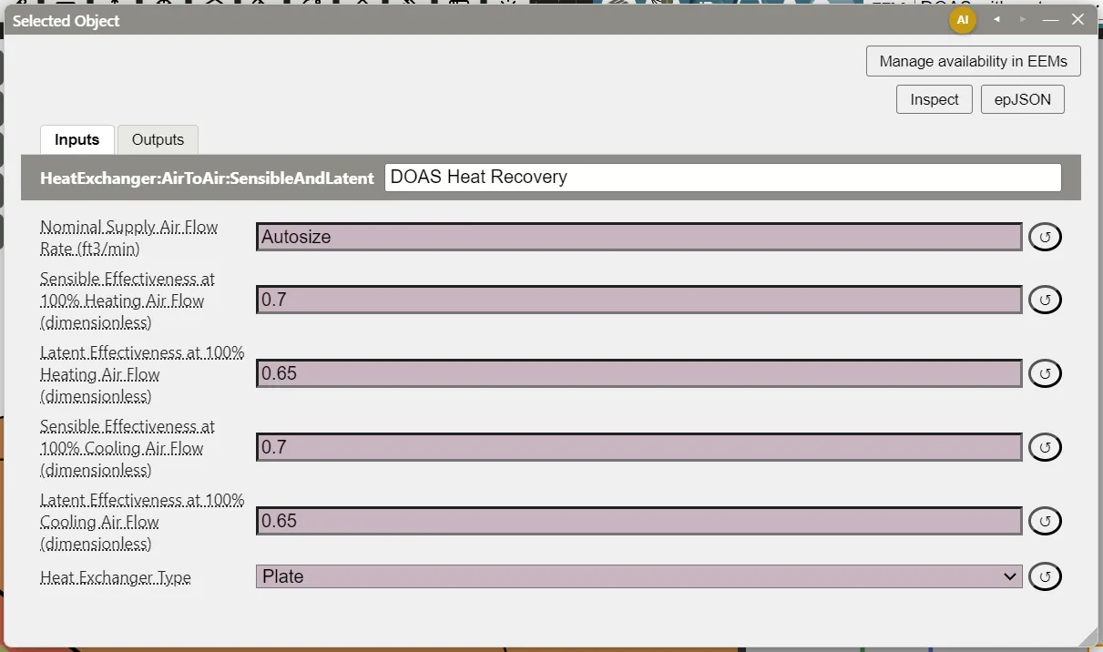
HeatExchanger:AirToAir:SensibleAndLatentacross the outdoor air and relief streams (0.70 sensible, 0.65 latent effectiveness); - a chilled water coil, a hot water coil, and a
Fan:VariableVolume, with an outdoor air reset on the supply temperature; Sizing:SystemType of Load to Size OnVentilationRequirement, and 100% Outdoor Air in Cooling and 100% Outdoor Air in HeatingYes;- an
AirTerminal:SingleDuct:VAV:NoReheatat Constant Minimum Air Flow Fraction 1.0, so each zone receives its design ventilation air.
It provides ventilation only; combine its EEM with a zone equipment system’s, such as Fan Coil (Energy Efficiency Measures (EEMs)).
To build one from Add AirLoopHVAC, set the three Sizing:System fields (Air Loops, Branches, and Nodes), add heat recovery and any preheat coil to the outdoor air stream, and connect a terminal. The 100% outdoor air fields affect sizing only; in operation the autosized minimum equals the design airflow, and a Minimum Fraction of Outdoor Air Schedule Name of Always On holds 100% outdoor air at any airflow.
5.2 Delivering DOAS air to zone units
- A terminal beside the unit. Assign both to the zone in EP3 - Select Zone Conditioning Equipment, the DOAS terminal first, so the unit meets the load left after the ventilation air (Zone-Level HVAC Equipment and Zone Sizing).
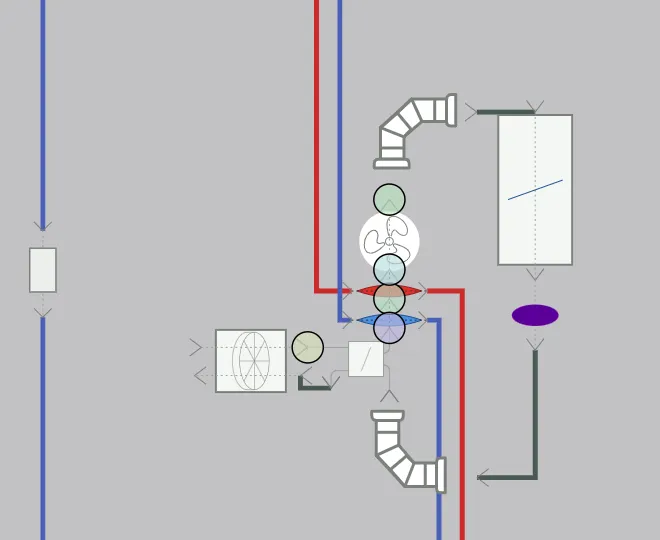
- An air terminal mixer. The unit’s Air Terminal Mixer Type
AirTerminal:SingleDuct:Mixerbrings the DOAS air into the unit’s inlet (InletSide) or outlet (SupplySide) and replaces the unit’s outdoor air mixer (Air Loops, Branches, and Nodes). The mixer’s Design Specification Outdoor Air Object Name, left blank, takes the zone’s, then theZoneType’s ZoneHVAC Design Specification Outdoor Air Object Name; the Zone columns of its tab show what each zone inherits.
Account for Dedicated Outdoor Air System on Sizing:Zone sizes the zone units for the load net of the DOAS air (Zone-Level HVAC Equipment and Zone Sizing).
5.3 Ventilation without an air loop
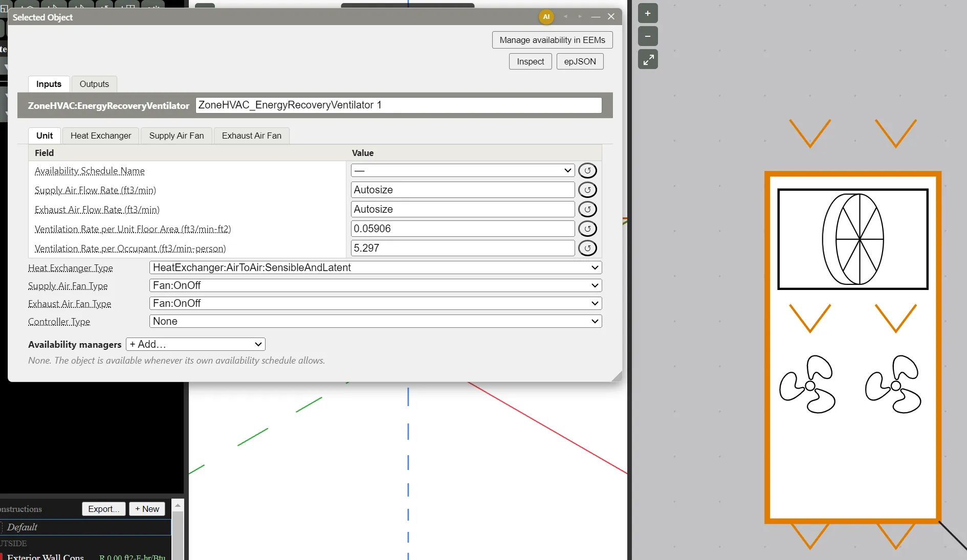
ZoneHVAC:EnergyRecoveryVentilator supplies outdoor air to one zone through a heat exchanger and exhausts zone air through its other side. Its tabs are Heat Exchanger (HeatExchanger:AirToAir:SensibleAndLatent), Supply Air Fan and Exhaust Air Fan (Fan:OnOff or Fan:SystemModel), and an optional Controller (ZoneHVAC:EnergyRecoveryVentilator:Controller) for economizer and high humidity control, whose humidistat zone is the zone served. Supply Air Flow Rate and Exhaust Air Flow Rate start at Autosize, sized from Ventilation Rate per Unit Floor Area and Ventilation Rate per Occupant. Assign it ahead of the zone’s heating and cooling equipment.
ZoneHVAC:UnitVentilator, with its Outdoor Air Control Type (FixedAmount, VariablePercent, FixedTemperature), also ventilates a zone directly (Zone-Level HVAC Equipment and Zone Sizing). AirLoopHVAC:DedicatedOutdoorAirSystem, one outdoor air system serving several air loops, and ZoneHVAC:OutdoorAirUnit are not available in EP3.
6. Energy recovery
6.1 Placing a heat exchanger
HeatExchanger:AirToAir:SensibleAndLatent is under Air Loop Equipment in the HVAC Components dialog. Its supply side carries outdoor air to the mixer; its exhaust side carries relief air out.
With Draw Branch Connections (The HVAC Outliner and Creating HVAC Systems), connect its supply side to a node on the mixer’s Outdoor Air Stream: EP3 places its exhaust side on the same mixer’s Relief Stream in the same step (and the reverse, starting from the exhaust side). Either side can be erased and reconnected. Components ahead of it on the outdoor air stream see raw outdoor air, so a frost-protection preheat coil goes there.
6.2 HeatExchanger:AirToAir:SensibleAndLatent
| Field | Default | Purpose |
|---|---|---|
| Nominal Supply Air Flow Rate | Autosize | The flow the 100% effectiveness values apply at. |
| Sensible Effectiveness at 100% Heating Air Flow, Latent Effectiveness at 100% Heating Air Flow, and the two cooling equivalents | 0.7 | Rated effectiveness. A heat exchanger added in EP3, alone or in a ZoneHVAC:EnergyRecoveryVentilator, starts at 0.7; an imported one keeps the file’s values (EnergyPlus’s default is 0). The Validation dialog’s Heat Exchanger Effectiveness check warns when all four are 0. |
| Sensible Effectiveness of Heating Air Flow Curve Name and three similar fields | Blank | Curves scaling each effectiveness with airflow. In an EnergyPlus 23.1 or 23.2 model these are replaced by Sensible Effectiveness at 75% Heating Air Flow and its three equivalents (EnergyPlus Versions). |
| Supply Air Outlet Temperature Control | No |
Yes modulates the wheel or a bypass to hold a setpoint on the supply air outlet, which then needs a setpoint manager. |
| Heat Exchanger Type | Plate |
Plate or Rotary. |
| Frost Control Type | None |
Or ExhaustAirRecirculation, ExhaustOnly, MinimumExhaustTemperature, with Threshold Temperature 1.7°C (35.1°F). |
| Economizer Lockout | Yes |
Bypasses the plate or stops the wheel while the economizer or high humidity control is active. |
Enter ratings as fractions: a wheel rated 72% sensible and 61% latent in heating takes 0.72 and 0.61. The rating conditions are those of ARI Standard 1060: 1.7°C (35°F) outdoor and 21°C (70°F) exhaust air for heating, 35°C (95°F) and 24°C (75°F) for cooling.
6.3 Heat recovery and the economizer
Recovering heat while the economizer is cooling with outdoor air works against it. With Economizer Lockout Yes, the Controller:OutdoorAir Heat Recovery Bypass Control Type sets when the heat exchanger is bypassed: BypassWhenWithinEconomizerLimits (the default) whenever outdoor air is within the economizer limits, or BypassWhenOAFlowGreaterThanMinimum once the damper opens past the minimum. Both, and MinimumFlowWithBypass, need an Economizer Control Type other than NoEconomizer. With Supply Air Outlet Temperature Control Yes, set the outlet setpoint to the Economizer Minimum Limit Dry-Bulb Temperature.
6.4 Worked example: recovered heat on a winter hour
A DOAS draws 0.4719 m³/s (1,000 cfm) of outdoor air at −10°C (14°F) through a heat exchanger of 0.70 sensible effectiveness, with balanced exhaust at 21°C (69.8°F):
Tout = Toa + ε (Tex − Toa) = −10 + 0.70 × 31 = 11.7°C
Q = ṁ·cp·ΔT = 0.4719 × 1.2 × 1.006 × 21.7 = 12.4 kW
Check in IP units. 14 + 0.70 × (69.8 − 14) = 14 + 39.1 = 53.1°F (11.7°C), and Q = 1.08 × 1,000 × 39.1 = 42,200 Btu/h = 12.4 kW. The heating coil downstream starts from 11.7°C instead of −10°C.
6.5 Other heat recovery
A ZoneHVAC:EnergyRecoveryVentilator’s heat exchanger has the same fields, on its Heat Exchanger tab. A desiccant wheel (HeatExchanger:Desiccant:BalancedFlow) is available inside a Dehumidifier:Desiccant:System. HeatExchanger:AirToAir:FlatPlate is not available.
7. Checking your work
- Before simulating: on each air loop, check the
Controller:OutdoorAirminimum (lowered when DCV is on), a setpoint on the mixed air node when there is an economizer, and effectiveness values on each heat exchanger. Check that terminals meant to enforce outdoor air show aDesignSpecification:OutdoorAirin their zone columns. - After the run: request Air System Outdoor Air Flow Fraction, Air System Outdoor Air Economizer Status, Air System Outdoor Air Mechanical Ventilation Requested Mass Flow Rate, Air System Outdoor Air Heat Recovery Bypass Status, Heat Exchanger Sensible Heating Rate, and Zone Air Terminal Outdoor Air Volume Flow Rate as output variables (Viewing and Interpreting Results). The Component Sizing Summary lists the autosized outdoor air flows.
8. Where to Look Next
- Air-Side System Fundamentals — mixing and economizer decisions.
- Zone-Level HVAC Equipment and Zone Sizing — zone units, equipment order, and
Sizing:ZoneDOAS fields. - Air Loops, Branches, and Nodes — outdoor air streams,
Sizing:System, the air terminal mixer, and setpoint managers. - Controllers and Availability Managers — controllers, the humidistat, and ventilation-driven availability managers.
- Energy Efficiency Measures (EEMs) — combining a DOAS with a zone system, and DCV or heat recovery as a measure.
This handbook is also built into EP3 (Help), where its EnergyPlus links open the EnergyPlus Reference. Technical specifications · Book a demo