Air-Side System Fundamentals
1. Overview
The HVAC chapters that follow use a shared vocabulary: sensible and latent load, humidity ratio, supply air condition, economizer, dedicated outdoor air. EnergyPlus’s air-side objects are built on these terms, and EP3 shows their fields under the EnergyPlus labels, so a field such as Zone Cooling Design Supply Air Humidity Ratio or Gross Rated Sensible Heat Ratio means what the psychrometrics says it means. This chapter defines that vocabulary once and works the calculations behind it by hand, so a reader can check the numbers entered in a model.
EP3 does not compute psychrometric properties. It collects the inputs (design temperatures, humidity ratios, sensible heat ratios, economizer limits) that EnergyPlus’s psychrometric routines use during the simulation. Where a concept below corresponds to an EP3 field, the field is named with its label in the app; the rest is engineering background.
Each concept is picked up again, with the dialogs and fields in full, in the chapter that owns it:
- The HVAC Outliner and Creating HVAC Systems: building a system on the HVAC side.
- Zone-Level HVAC Equipment and Zone Sizing: zone equipment and
Sizing:Zone. - Air Loops, Branches, and Nodes:
AirLoopHVAC, terminals, andSizing:System. - Fans and Fan Power: fan inputs and fan heat.
- Outdoor Air, Ventilation, and Energy Recovery: the outdoor air system, economizers, and DOAS.
2. Psychrometric properties and the chart
Conditioning air means controlling its temperature and the moisture it carries. The two can change independently, and they draw on different equipment capacity: a cooling coil’s load splits into a sensible part (lowering dry-bulb temperature) and a latent part (condensing moisture out of the airstream), and a coil sized for the sensible part alone under-dehumidifies however much sensible capacity it has (§3). An economizer’s decision about whether outdoor air is favorable can come out differently depending on whether it compares temperature or total heat content (§6). Describing an air sample, and predicting what happens when two airstreams mix or a coil removes moisture, requires tracking temperature and moisture together.
2.1 The properties
At a given barometric pressure, two independent properties fix the state of moist air, and every other property follows from them. The properties that appear in EnergyPlus fields:
- Dry-bulb temperature (T): the reading of an ordinary thermometer, and the meaning of “temperature” elsewhere in this handbook.
- Humidity ratio (W): mass of water vapor per unit mass of dry air (kg/kg, or lb/lb). EnergyPlus sizing and coil objects use it for moisture content because it does not change when air is heated or cooled without adding or removing moisture.
- Relative humidity (RH): the ratio of the water vapor pressure to the saturation vapor pressure at the same dry-bulb temperature. RH changes when air is heated or cooled, even though its moisture content is unchanged. Humidistat setpoints (
ZoneControl:Humidistat) are in RH; most sizing and coil fields are not. - Wet-bulb temperature (Twb): the temperature air reaches when water evaporates into it at constant enthalpy until it saturates. Evaporative coolers and design-day weather data use it.
- Dew point (Tdp): the temperature at which air saturates when cooled at constant humidity ratio. It appears in the fixed dew point economizer limit and in design-day data.
- Specific enthalpy (h): the total heat content of moist air per unit mass of dry air (kJ/kg, or Btu/lb). It combines sensible and latent heat in one number, which is why enthalpy economizers behave differently from dry-bulb economizers (§6).
Enthalpy follows from dry-bulb temperature and humidity ratio (ASHRAE Handbook—Fundamentals, Psychrometrics chapter):
h [kJ/kg] = 1.006 T [°C] + W (2,501 + 1.86 T [°C])
h [Btu/lb] = 0.240 T [°F] + W (1,061 + 0.444 T [°F])
The two forms use different reference points (0°C and 0°F), so an enthalpy in one system does not convert directly to the other; enthalpy differences do (1 Btu/lb = 2.326 kJ/kg).
2.2 Processes on the chart
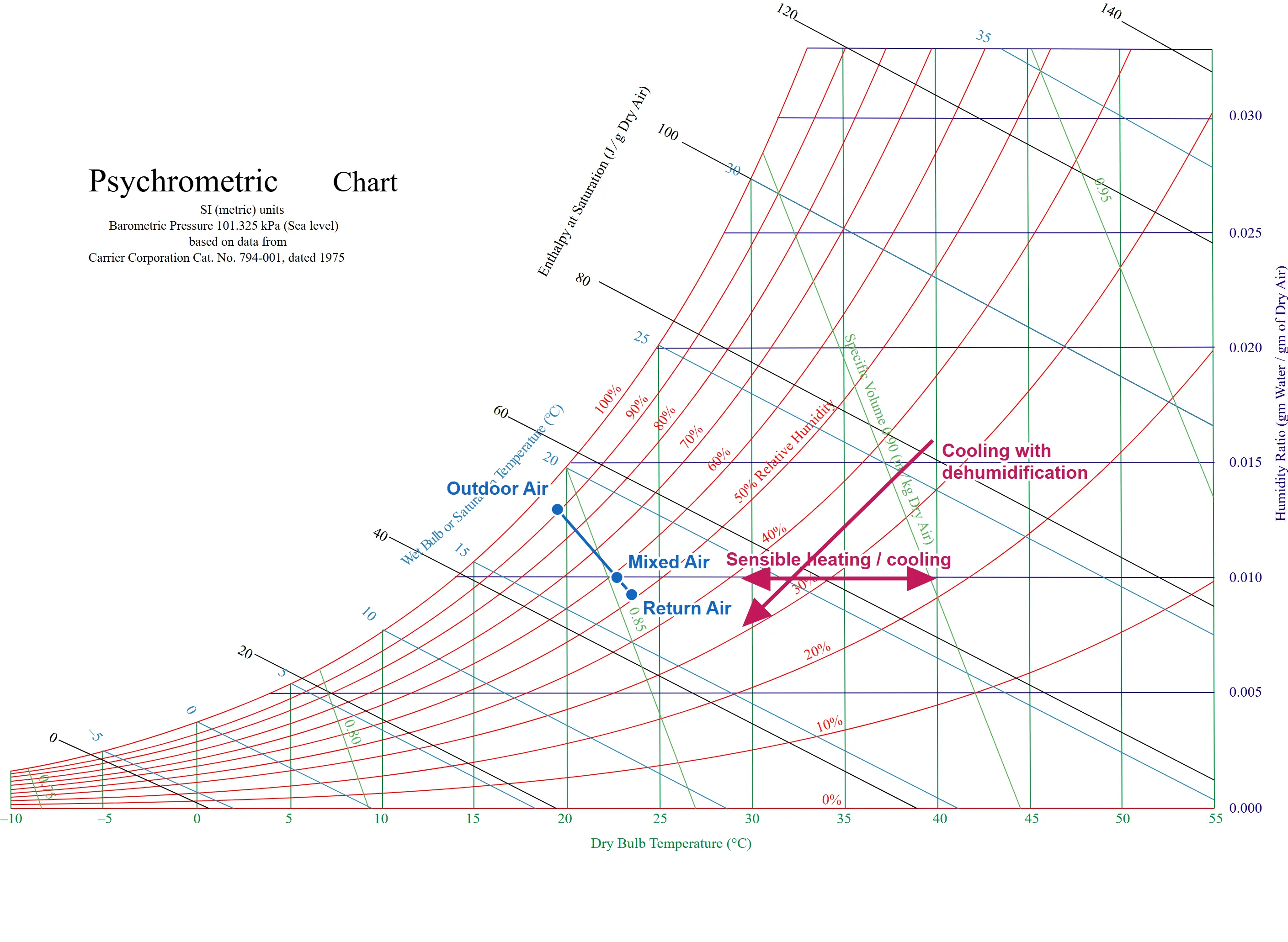
A psychrometric chart plots dry-bulb temperature on the horizontal axis and humidity ratio on the vertical axis, with curves of constant RH, wet-bulb temperature, and enthalpy overlaid, so one point fixes every property. Three processes recur in air-side HVAC:
- Sensible heating or cooling: a horizontal move. Dry-bulb temperature changes at constant humidity ratio; no moisture is added or removed.
- Cooling with dehumidification: a move down and to the left. A cooling coil whose surface is below the entering air’s dew point condenses water vapor onto the coil, where it drains away, so both temperature and humidity ratio fall. §3 covers the sensible and latent split this represents.
- Humidification: a move up. Evaporative (adiabatic) humidification follows a line of constant wet-bulb temperature, up and to the left, because evaporating water cools the air; steam humidification moves nearly straight up, adding moisture with little temperature change.
2.3 Mixing two airstreams
When two airstreams mix, such as return air and outdoor air in a mixing box, the mixed state lies on the straight line between the two entering states, at a position set by their dry-air mass flow rates:
Tmix = (ṁ₁T₁ + ṁ₂T₂) ÷ (ṁ₁ + ṁ₂), and the same weighted average for humidity ratio.
Enthalpy mixes the same way, to the precision used in design: the mixed enthalpy computed from the mixed T and W matches the mass-weighted average of the two entering enthalpies. §6.1 works a numeric mixing example.
3. Sensible and latent heat
A cooling or heating process changes the air’s dry-bulb temperature (sensible heat transfer). When a cooling coil’s surface is below the entering air’s dew point, it also removes moisture (latent heat transfer). The sensible heat ratio (SHR) is the sensible fraction of the total:
SHR = Qsensible ÷ Qtotal = Qsensible ÷ (Qsensible + Qlatent)
Comfort-cooling zones commonly fall around SHR 0.75 to 0.85. A space with high occupant density or process moisture has a lower SHR (more latent load); a space dominated by envelope, solar, and lighting loads with few occupants has a higher one, approaching 1.0.
3.1 Worked example: supply airflow and humidity ratio from zone loads
Take a zone with a design sensible cooling load of 10.0 kW (34,120 Btu/h) and a design latent cooling load of 2.5 kW (8,530 Btu/h), so SHR = 10.0 ÷ 12.5 = 0.80. These are the kind of figures the zone heat balance produces (Heating and Cooling Loads: From Design Day to Annual Profile) and are taken as given here. The room is held at 24°C (75.2°F) dry-bulb and 50% RH, which gives Wroom = 0.00930 kg/kg and hroom = 1.006(24) + 0.00930(2,501 + 1.86 × 24) = 24.14 + 23.67 = 47.8 kJ/kg. This room state recurs in §6.1.
Sensible heat. For standard air (density ρ = 1.2 kg/m³, specific heat cp = 1.006 kJ/kg·K):
Qs [W] = V̇ [L/s] × ρ × cp × ΔT ≈ 1.2 × V̇ [L/s] × ΔT [°C]
The factor is 1.2 kg/m³ × 1,006 J/kg·K × 0.001 m³/L = 1.207, commonly rounded to 1.2 (ASHRAE Handbook—Fundamentals). With a design supply air temperature difference of ΔT = 11°C (19.8°F), a common VAV cooling design point and the quantity Sizing:Zone takes as Zone Cooling Design Supply Air Temperature Difference (§4.1), the supply air temperature is 24 − 11 = 13°C (55.4°F) and the required supply airflow is:
V̇ = Qs ÷ (1.2 × ΔT) = 10,000 ÷ (1.2 × 11) = 10,000 ÷ 13.2 = 758 L/s (0.758 m³/s)
Latent heat. Using the latent heat of vaporization at 0°C, hfg = 2,501 kJ/kg (the constant in the enthalpy equation of §2.1):
Ql [W] = V̇ [L/s] × ρ × hfg × ΔW ≈ 3,001 × V̇ [L/s] × ΔW [kg/kg]
The factor is 1.2 kg/m³ × 2,501,000 J/kg × 0.001 m³/L = 3,001 (ASHRAE Handbook—Fundamentals). Solving for the humidity ratio drop at 758 L/s:
ΔW = Ql ÷ (3,001 × V̇) = 2,500 ÷ (3,001 × 758) = 0.0011 kg/kg
The required supply air humidity ratio is Wsupply = Wroom − ΔW = 0.0093 − 0.0011 = 0.0082 kg/kg, the quantity Sizing:Zone takes as Zone Cooling Design Supply Air Humidity Ratio.
Check by total heat. The enthalpy drop is Δh ≈ cpΔT + hfgΔW = 1.006 × 11 + 2,501 × 0.0011 = 11.07 + 2.75 = 13.82 kJ/kg. The total heat equation, Qt [W] ≈ 1.2 × V̇ [L/s] × Δh [kJ/kg], gives 1.2 × 758 × 13.82 = 12,570 W, matching the 12,500 W target (10,000 + 2,500) within the rounding of ΔW.
Check in IP units. The standard-air IP factors are 1.08 for sensible heat (0.075 lb/ft³ × 0.24 Btu/lb·°F × 60 min/h), 4,840 for latent heat (0.075 × 60 × 1,076 Btu/lb), and 4.5 for total heat (0.075 × 60):
- Sensible: cfm = 34,120 ÷ (1.08 × 19.8) = 34,120 ÷ 21.38 = 1,596 cfm. 758 L/s is 1,606 cfm; the 0.6% difference comes from rounding the SI factor from 1.207 to 1.2 (10,000 ÷ (1.207 × 11) = 753 L/s = 1,596 cfm).
- Latent: ΔW = 8,530 ÷ (4,840 × 1,596) = 0.0011 lb/lb, the same as in SI, since humidity ratio is a ratio of masses.
- Total: Δh = 13.82 ÷ 2.326 = 5.94 Btu/lb, and Qt = 4.5 × 1,596 × 5.94 = 42,660 Btu/h = 12.5 kW.
These hand factors assume standard sea-level air and are for manual checks; EnergyPlus’s sizing calculations use air properties at the simulated conditions. §4.1 shows where the supply air temperature and humidity ratio are entered in EP3.
3.2 Rated SHR, apparatus dew point, and bypass factor
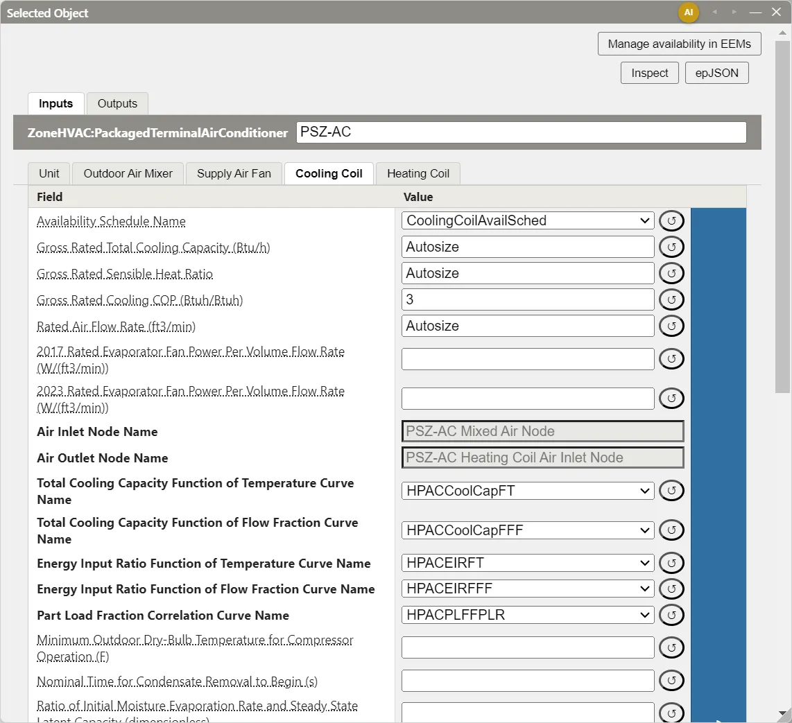
The SHR in §3.1 is the zone’s load SHR: a target the equipment must meet. A DX cooling coil’s Gross Rated Sensible Heat Ratio (on Coil:Cooling:DX:SingleSpeed, with per-speed equivalents on the multispeed and variable-speed coils) is a property of the coil: its SHR at the rating condition (air entering at 26.7°C dry-bulb and 19.4°C wet-bulb, 80°F and 67°F, at the coil’s Rated Air Flow Rate), excluding fan heat. The coil’s operating SHR at other entering conditions and airflows differs from the rated value, and the coil’s performance curves (Performance Curves: Part-Load and Efficiency Behavior) and sizing inputs describe how. The Model Wizard’s PSZ-AC template leaves it at Autosize, which EnergyPlus fills during sizing.
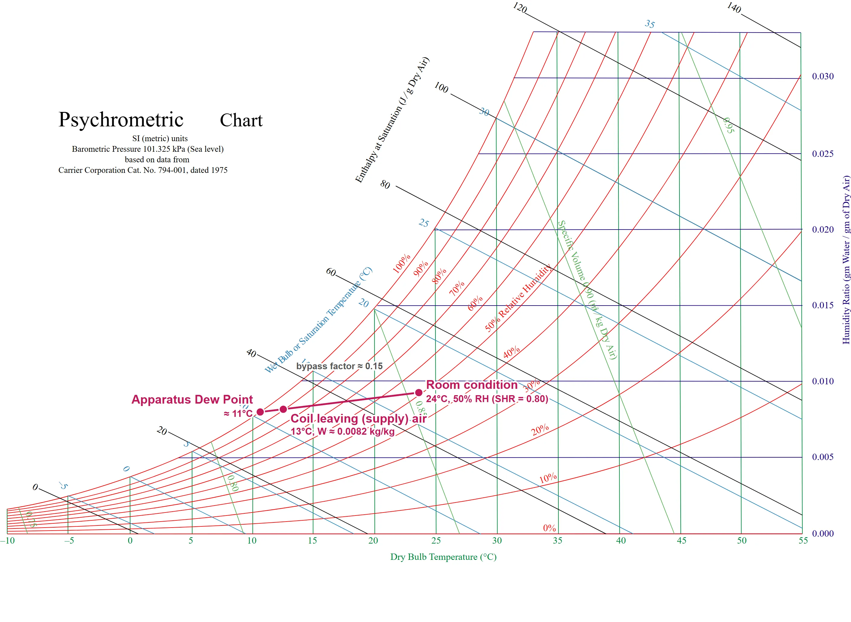
A coil does not bring all of the entering air to one leaving condition. Part of the air contacts the cold coil surface and leaves near the apparatus dew point (ADP), the saturated condition at the coil surface; part passes with little contact. The bypass factor (BF) is the fraction idealized as passing unchanged, and the leaving state lies on the line from the entering state to the ADP. EnergyPlus’s DX coil model uses this ADP/bypass factor approach: at the rating condition it finds the ADP on the saturation curve from the rated SHR, computes the rated bypass factor, and at each timestep adjusts it for the coil’s airflow and uses it to split sensible and latent capacity. The bypass factor and ADP are not inputs on the coil.
For the §3.1 example, with room air entering the coil (no outdoor air, for simplicity), the line from the room state (24°C, 0.0093) through the supply state (13°C, 0.0082) has a slope of 0.0011 ÷ 11 = 0.0001 kg/kg per °C. It meets the saturation curve at 10.6°C (51.2°F), where Wsat = 0.0080 kg/kg; this is the ADP, which the chart reads as about 11°C. EnergyPlus defines the bypass factor on enthalpy: hin = 47.8, hout = 1.006(13) + 0.0082(2,501 + 1.86 × 13) = 33.8, and hADP = 1.006(10.6) + 0.0080(2,501 + 1.86 × 10.6) = 30.8 kJ/kg, so BF = (33.8 − 30.8) ÷ (47.8 − 30.8) = 0.18. Measured along the temperature axis, (13 − 10.6) ÷ (24 − 10.6) gives the same 0.18, and the chart-rounded ADP of 11°C gives (13 − 11) ÷ (24 − 11) = 0.15. Either value falls in the 0.05 to 0.20 range typical of a well-selected coil, which confirms that the chosen supply state is one a coil can deliver.
3.3 Fan heat
A supply fan adds heat to the air it moves. When the motor sits in the airstream, all of the fan’s electric power ends up in the air; otherwise the motor’s losses leave the airstream. On Fan:VariableVolume, the fan’s power per unit airflow is Pressure Rise ÷ Fan Total Efficiency, and Motor In Airstream Fraction sets the share of motor losses added to the air.
The 5zone example’s supply fan has a Pressure Rise of 600 Pa (2.41 in. w.c.), a Fan Total Efficiency of 0.7, and a Motor In Airstream Fraction of 1.0. Its temperature rise is:
ΔTfan = (ΔP ÷ η) ÷ (ρ cp) = (600 ÷ 0.7) ÷ (1.2 × 1,006) = 857 ÷ 1,207 = 0.71°C
In IP units, ΔTfan [°F] = 0.371 × ΔP [in. w.c.] ÷ η = 0.371 × 2.41 ÷ 0.7 = 1.28°F, which is 0.71°C. The fan follows the coils on that loop’s supply branch (a draw-through fan), so a coil serving the §3.1 zone through it must leave the air at 13 − 0.7 = 12.3°C to deliver 13°C, and its sensible capacity includes the fan heat. Fans and Fan Power covers fan inputs.
4. Where the supply air condition is entered
§3.1 runs from loads and a chosen supply air condition to an airflow. EnergyPlus’s zone and system sizing runs the same relationship on the design days: it computes the zone loads, and from the supply air condition entered in the sizing objects it determines the airflow and coil capacity each zone and system needs.
4.1 Sizing:Zone
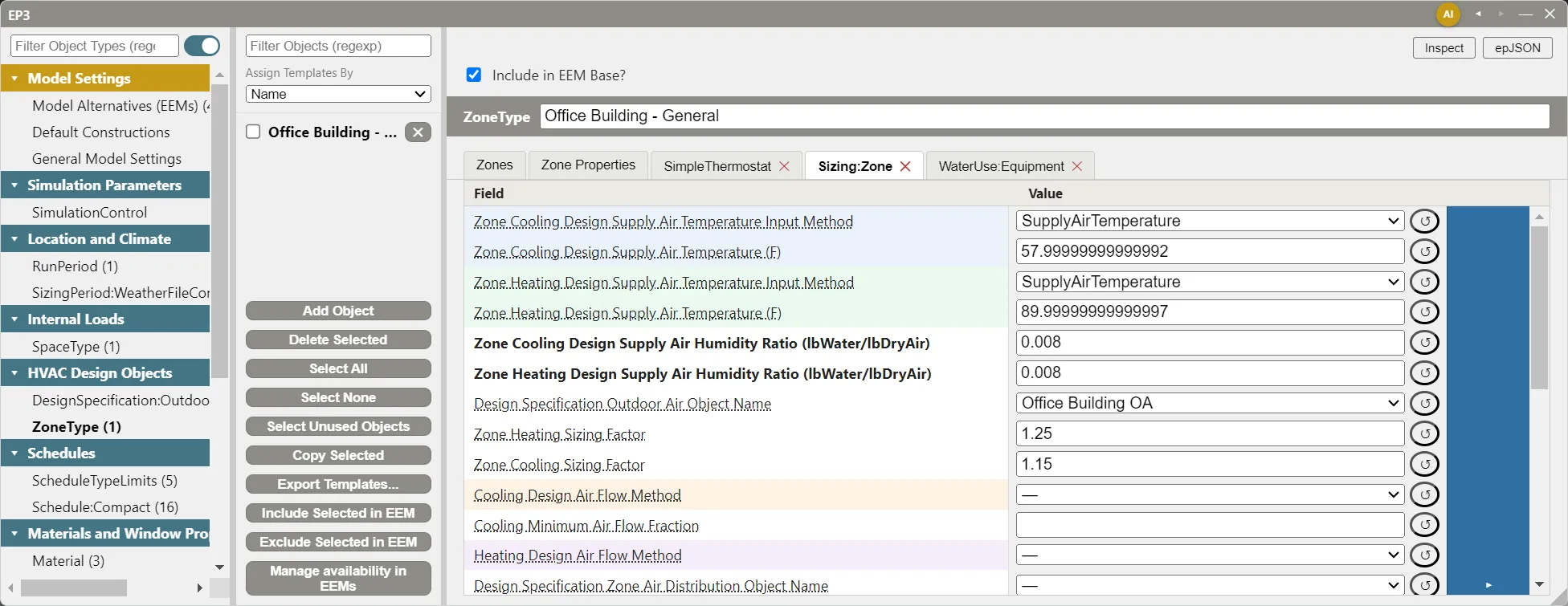
In a model built with templates, Sizing:Zone is a tab of the ZoneType in the main object dialog (Internal Loads, Space Types, and Zone Types). In an imported model, each zone has a separate Sizing:Zone object. The fields that carry the supply air condition:
| Field | Purpose |
|---|---|
| Zone Cooling Design Supply Air Temperature Input Method | SupplyAirTemperature (the default) or TemperatureDifference. The dialog shows only the field the method uses. |
| Zone Cooling Design Supply Air Temperature, or Zone Cooling Design Supply Air Temperature Difference | The supply air temperature, or its difference below the zone’s cooling setpoint. |
| Zone Heating Design Supply Air Temperature Input Method and its two fields | The heating equivalents. |
| Zone Cooling Design Supply Air Humidity Ratio, Zone Heating Design Supply Air Humidity Ratio | The supply air humidity ratio used in the zone’s design airflow calculation. Both are required. |
| Zone Load Sizing Method | Sensible Load Only No Latent Load (the default) sizes the airflow on the sensible load and lets the zone humidity float on the supply humidity ratios above. Sensible Load, Latent Load, and Sensible And Latent Load also compute the latent airflow; the last uses the larger of the sensible and latent airflows. |
| Zone Latent Cooling Design Supply Air Humidity Ratio Input Method | Used by the latent methods: HumidityRatioDifference (the default, with Zone Cooling Design Supply Air Humidity Ratio Difference, 0.005 kg/kg by default) or SupplyAirHumidityRatio (with Zone Dehumidification Design Supply Air Humidity Ratio). |
For the §3.1 zone, the entries are a Zone Cooling Design Supply Air Temperature of 13°C (55.4°F), or a Zone Cooling Design Supply Air Temperature Difference of 11°C (19.8°F), and a Zone Cooling Design Supply Air Humidity Ratio of 0.0082. With a latent sizing method, the default 0.005 difference would size the latent airflow at 2,500 ÷ (3,001 × 0.005) = 167 L/s (353 cfm); the 758 L/s sensible airflow is larger, so Sensible And Latent Load would keep 758 L/s.
The Model Wizard’s office templates set a Zone Cooling Design Supply Air Temperature of 14.4°C (58°F), a Zone Heating Design Supply Air Temperature of 32.2°C (90°F), and both humidity ratios at 0.008. With the 24°C room of §3.1, the 14.4°C supply gives ΔT = 9.6°C and an airflow of 10,000 ÷ (1.2 × 9.6) = 868 L/s (1,840 cfm), 15% more than at 13°C: a warmer supply air temperature needs more air for the same sensible load.
Zone-Level HVAC Equipment and Zone Sizing covers the rest of Sizing:Zone: design airflow methods, sizing factors, outdoor air, and how the results feed autosized equipment.
4.2 Sizing:System
An AirLoopHVAC owns a Sizing:System, shown in the air loop’s dialog below the loop’s fields. It takes the central air handler’s supply air condition: Central Cooling Design Supply Air Temperature and Central Heating Design Supply Air Temperature, with Central Cooling Design Supply Air Humidity Ratio and Central Heating Design Supply Air Humidity Ratio. Preheat Design Temperature, Preheat Design Humidity Ratio, Precool Design Temperature, and Precool Design Humidity Ratio describe outdoor air conditioned before it mixes with return air, as by coils on the outdoor air stream. Type of Load to Size On, Type of Zone Sum to Use, and 100% Outdoor Air in Cooling / 100% Outdoor Air in Heating set how the system reconciles the zones it serves.
The 5zone example’s VAV loop sizes on a Central Cooling Design Supply Air Temperature of 12.8°C (55°F) and a Central Heating Design Supply Air Temperature of 16.7°C (62.1°F), with outdoor air preheated to 4.5°C (40.1°F) and precooled to 11.0°C (51.8°F) at a humidity ratio of 0.008.
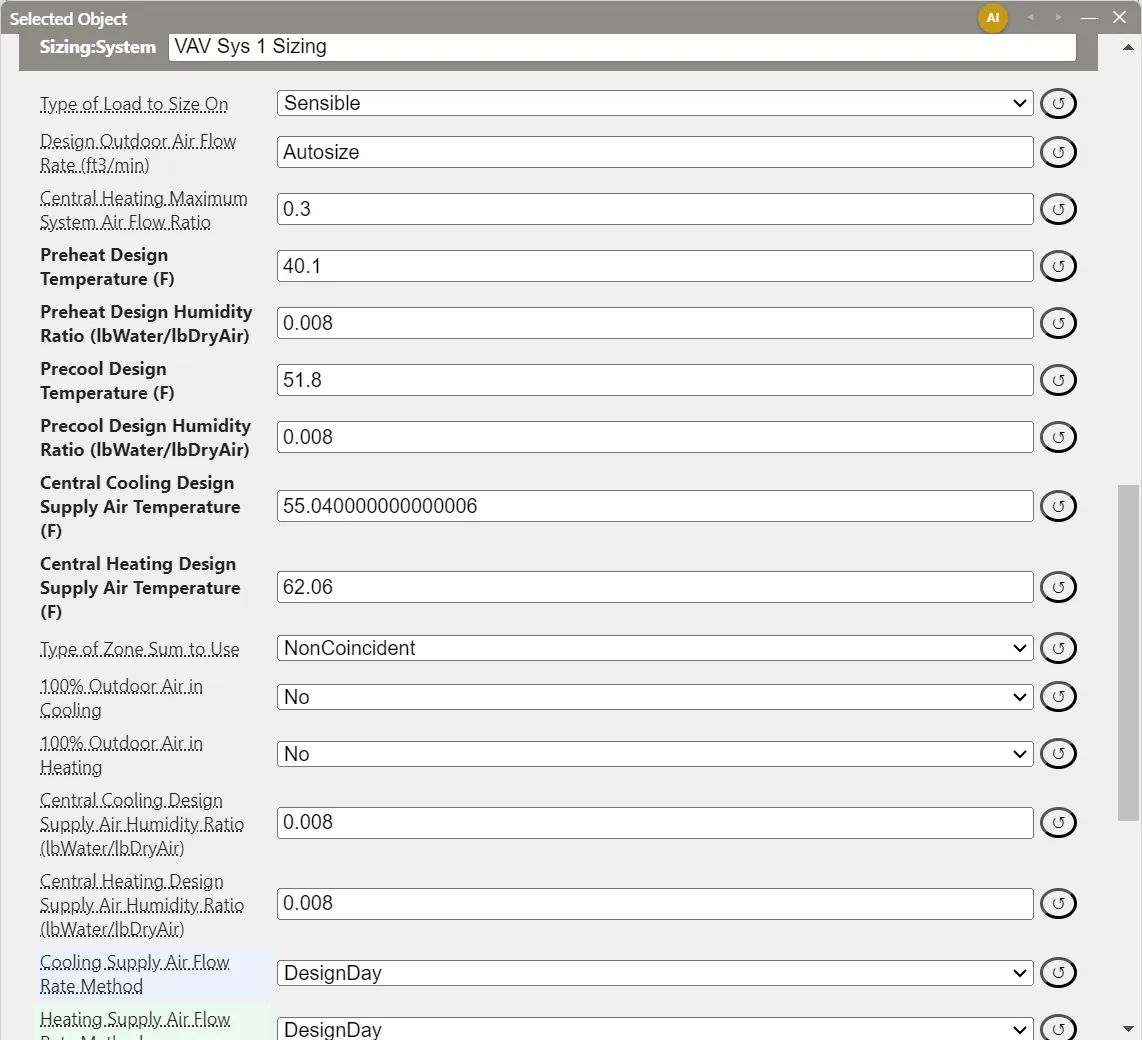
Air Loops, Branches, and Nodes covers Sizing:System in full.
5. Air-side system architecture
The pieces of an air-side system, and where each is built in EP3:
- Single-zone and multi-zone systems. A single-zone system serves one zone from one air handler, sized and controlled for that zone. A multi-zone system shares one central air handler across several zones through a duct distribution, with a terminal at each zone reconciling what the central system delivers with what the zone needs.
- Constant volume (CV) and variable air volume (VAV). A CV system holds supply airflow fixed and varies capacity by other means: cycling, reheat, or staged fan and compressor speeds. A VAV system varies each zone’s airflow with its load and holds the supply air temperature comparatively fixed. At part load, a VAV system moves less air across the coil at a similar supply temperature, which shifts the coil’s operating SHR; a coil sized only for the design sensible/latent split can under-dehumidify as airflow drops.
- The mixed-air path. Return air and outdoor air for ventilation combine in a mixing box (§2.3) ahead of the main coils, and the return air not recirculated leaves through a relief path. On an
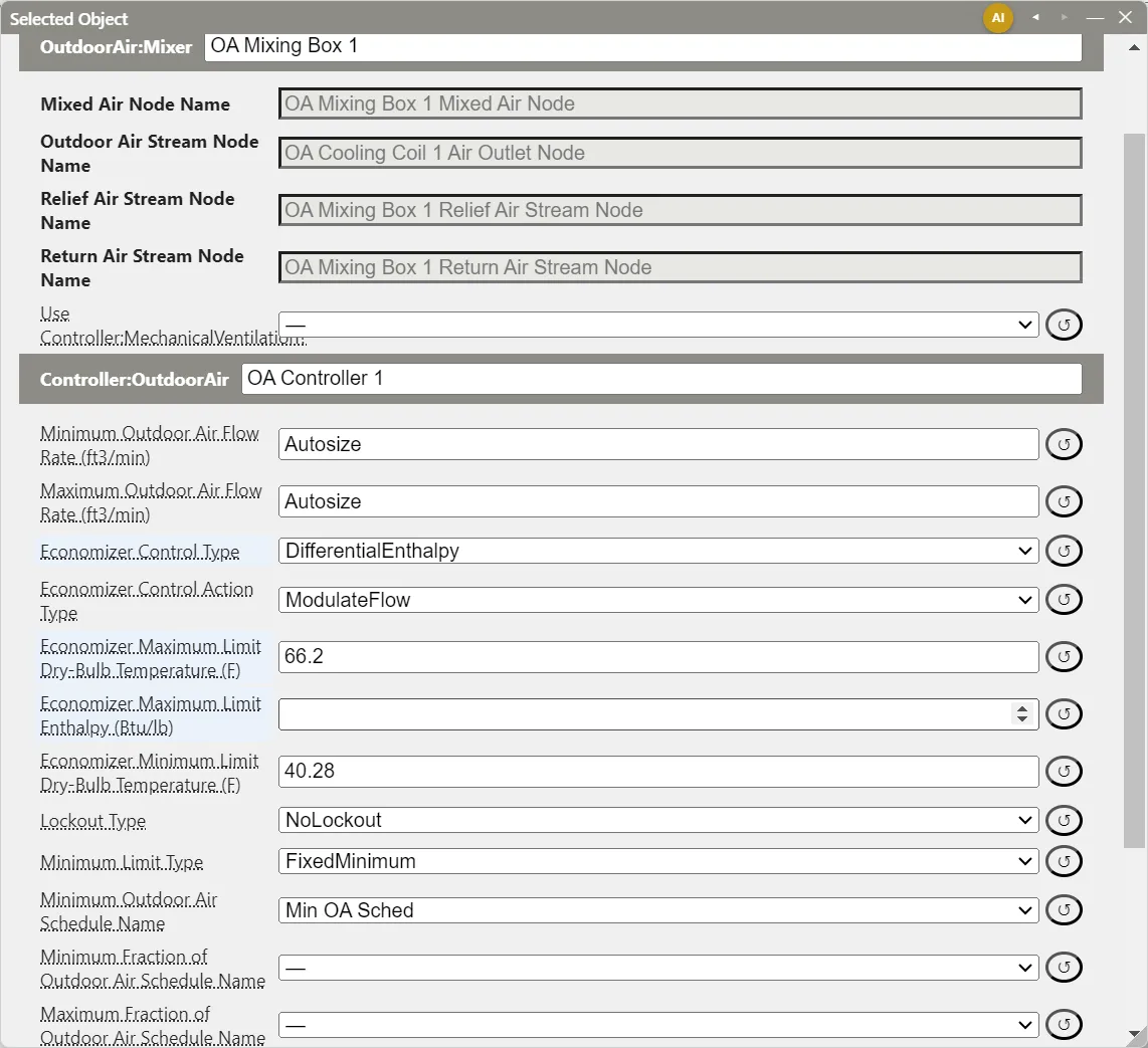
AirLoopHVAC, this is anOutdoorAir:Mixeron the supply branch, with an outdoor air stream branch (where preheat coils and heat recovery go) and a relief stream branch. ItsController:OutdoorAir, which sets the outdoor airflow and the economizer (§6), is edited in the mixer’s dialog. Outdoor Air, Ventilation, and Energy Recovery covers both. - Dedicated outdoor air systems (DOAS). A DOAS conditions and delivers ventilation air through a separate path, while other equipment handles each zone’s sensible load. In EP3, a DOAS is an
AirLoopHVACwhoseSizing:Systemhas Type of Load to Size On set toVentilationRequirementand 100% Outdoor Air in Cooling and 100% Outdoor Air in Heating set toYes; the Model Wizard’s DOAS with water coils system is built this way, with a sensible and latent heat recovery exchanger on its outdoor air stream. A zone served by a DOAS terminal and a zone unit lists both in its equipment list, andSizing:Zone’s Account for Dedicated Outdoor Air System field lets zone sizing credit the DOAS air. - Terminal units. On a multi-zone system, the terminal (a VAV box, with or without a reheat coil) is where central airflow meets each zone’s demand. In EP3, terminals sit on the air loop’s demand side in the HVAC diagram and are assigned to zones like zone equipment, in the Select Zone Conditioning Equipment dialog (Air Loops, Branches, and Nodes).
- Central and zone-level equipment. Cooling and heating can happen centrally, in coils on the air loop serving every zone, or locally, in zone equipment (fan coils, PTACs, VRF terminals) that conditions one zone each. The psychrometrics of this chapter applies to both; the objects and controls differ. The HVAC Outliner and Creating HVAC Systems compares the two families, and Zone-Level HVAC Equipment and Zone Sizing covers zone equipment.
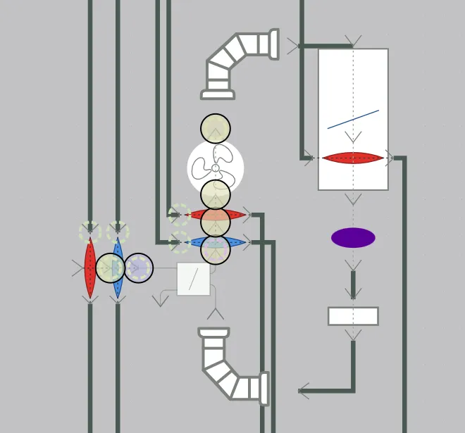
The 5zone example’s VAV loop shows a multi-zone VAV system with each of these parts: an outdoor air mixer with heating and cooling coils on the outdoor air stream, main cooling and heating coils, a draw-through supply fan, and a VAV terminal with a reheat coil for each zone, with the coils’ water sides on the chilled and hot water loops.
6. Economizers
An economizer uses outdoor air to meet some or all of a system’s cooling load when outdoor conditions allow, reducing mechanical cooling. Whether outdoor air is favorable depends on the property compared, so Controller:OutdoorAir’s Economizer Control Type offers types built on different properties: NoEconomizer, FixedDryBulb, FixedEnthalpy, DifferentialDryBulb, DifferentialEnthalpy, DifferentialDryBulbAndEnthalpy, FixedDewPointAndDryBulb, and ElectronicEnthalpy.
- A dry-bulb economizer compares outdoor air temperature with return air temperature (differential) or with a limit (fixed). It suits dry climates, but can admit cool, humid outdoor air that carries more total heat than the return air.
- An enthalpy economizer compares total heat content, and rejects outdoor air that is cool but humid.
- A fixed type compares the outdoor condition with an absolute limit; a differential type compares it with the return air.
In EP3, Controller:OutdoorAir is part of its OutdoorAir:Mixer and appears in the mixer’s dialog while the mixer is on an air loop. The dialog shows the limit fields the chosen type uses: Economizer Maximum Limit Dry-Bulb Temperature for FixedDryBulb, Economizer Maximum Limit Enthalpy for FixedEnthalpy, both for the differential types, the dry-bulb and Economizer Maximum Limit Dewpoint Temperature for FixedDewPointAndDryBulb, and Electronic Enthalpy Limit Curve Name for ElectronicEnthalpy. Economizer Minimum Limit Dry-Bulb Temperature is shown for every type. A limit that has a value is applied whatever the type, so it stays in the export when hidden.
6.1 Worked example: dry-bulb and enthalpy economizer decisions
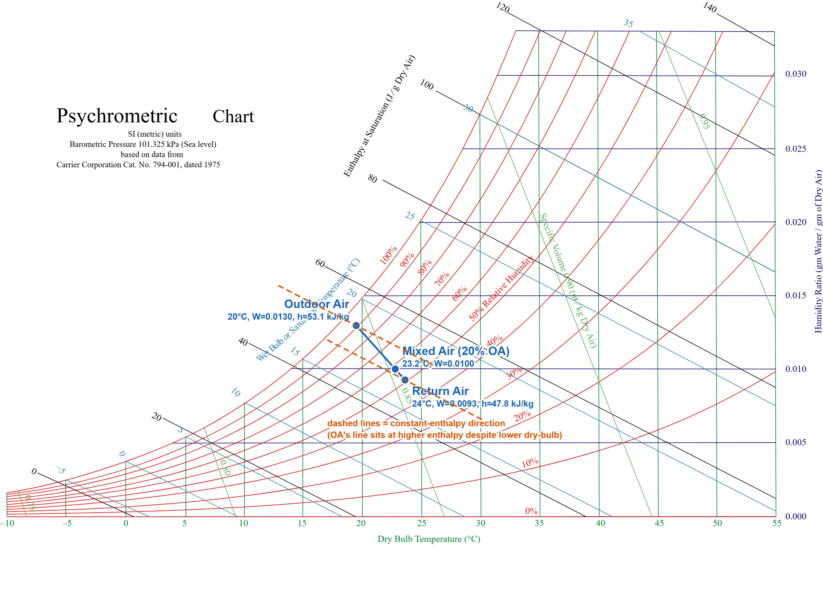
Return air is at the §3.1 room condition: 24°C (75.2°F), W = 0.0093 kg/kg, h = 47.8 kJ/kg. Outdoor air is at 20°C (68°F), W = 0.0130 kg/kg (89% RH), a cool, humid, overcast day:
hoa = 1.006(20) + 0.0130(2,501 + 1.86 × 20) = 20.12 + 0.0130 × 2,538.2 = 20.12 + 33.00 = 53.1 kJ/kg
By dry-bulb temperature, outdoor air (20°C) is cooler than return air (24°C), so a dry-bulb economizer opens the outdoor air damper. By enthalpy, outdoor air (53.1 kJ/kg) carries more total heat than return air (47.8 kJ/kg), so an enthalpy economizer keeps the damper at minimum: more of this air would raise the coil’s total load. This is why energy codes such as ASHRAE 90.1 restrict dry-bulb-only economizer control in humid climates.
Check in IP units. hra = 0.240(75.2) + 0.0093(1,061 + 0.444 × 75.2) = 18.05 + 10.18 = 28.23 Btu/lb, and hoa = 0.240(68) + 0.0130(1,061 + 0.444 × 68) = 16.32 + 14.19 = 30.51 Btu/lb. The difference, 2.28 Btu/lb, is 2.28 × 2.326 = 5.30 kJ/kg, matching 53.1 − 47.8 = 5.3 kJ/kg.
Mixed air at 20% outdoor air and 80% return air (a typical minimum outdoor air fraction, by mass), using §2.3:
Tmix = 0.2(20) + 0.8(24) = 4.0 + 19.2 = 23.2°C (73.8°F)
Wmix = 0.2(0.0130) + 0.8(0.0093) = 0.00260 + 0.00744 = 0.01004 kg/kg
Check: two paths to the mixed enthalpy. From the mixed state, hmix = 1.006(23.2) + 0.01004(2,501 + 1.86 × 23.2) = 23.34 + 0.01004 × 2,544.2 = 23.34 + 25.54 = 48.9 kJ/kg. As the mass-weighted average of the entering enthalpies, hmix = 0.2(53.1) + 0.8(47.8) = 10.62 + 38.24 = 48.9 kJ/kg. The two agree. In IP units, 0.2(30.51) + 0.8(28.23) = 28.69 Btu/lb, and from the mixed state, 0.240(73.8) + 0.01004(1,061 + 0.444 × 73.8) = 17.71 + 10.98 = 28.69 Btu/lb.
Outdoor Air, Ventilation, and Energy Recovery covers setting economizer limits, lockout, and minimum outdoor air.
7. Vocabulary recap
| Term | Meaning | Where it appears in EP3 |
|---|---|---|
| Dry-bulb temperature | Ordinary air temperature | Supply air temperature fields on Sizing:Zone and Sizing:System (§4) |
| Humidity ratio (W) | Mass of water vapor per mass of dry air | Supply air humidity ratio fields on Sizing:Zone and Sizing:System; preheat and precool humidity ratios (§4) |
| Relative humidity (RH) | Vapor pressure as a fraction of saturation, at the air’s temperature | ZoneControl:Humidistat setpoint schedules |
| Wet-bulb temperature | Temperature reached by adiabatic saturation | Evaporative cooler performance; design-day weather data |
| Dew point | Saturation temperature at constant humidity ratio | Economizer Maximum Limit Dewpoint Temperature (§6) |
| Specific enthalpy (h) | Total (sensible plus latent) heat per mass of dry air | Enthalpy economizer types and Economizer Maximum Limit Enthalpy (§6) |
| Sensible heat ratio (SHR) | Sensible heat as a fraction of total heat | Gross Rated Sensible Heat Ratio on DX cooling coils (§3.2) |
| Apparatus dew point, bypass factor | The coil-surface saturated state, and the fraction of air idealized as bypassing it | Computed inside EnergyPlus’s DX coil model from the rated SHR; not inputs (§3.2) |
| Economizer | Using favorable outdoor air in place of mechanical cooling | Controller:OutdoorAir’s Economizer Control Type and limits, in the OutdoorAir:Mixer dialog (§6) |
| DOAS | Ventilation air conditioned and delivered apart from zone sensible conditioning | An AirLoopHVAC sized on VentilationRequirement with 100% outdoor air (§5) |
8. Where to go next
- The HVAC Outliner and Creating HVAC Systems: placing loops and equipment on the HVAC side, and choosing between zone equipment and air loops.
- Zone-Level HVAC Equipment and Zone Sizing: zone equipment, the zone equipment list, and
Sizing:Zone. - Air Loops, Branches, and Nodes: building an
AirLoopHVAC, its terminals, setpoint managers, andSizing:System. - Fans and Fan Power: fan types, fan power inputs, and worked fan power examples.
- Outdoor Air, Ventilation, and Energy Recovery: the outdoor air system, economizer control, demand-controlled ventilation, DOAS, and heat recovery.
This handbook is also built into EP3 (Help), where its EnergyPlus links open the EnergyPlus Reference. Technical specifications · Book a demo