Heating and Cooling Loads: From Design Day to Annual Profile
1. Overview
A zone’s heating or cooling load is the heat that must be added to or removed from its air to hold it at the thermostat setpoint. EnergyPlus calculates it from everything earlier chapters set up: geometry and constructions (Creating Building Geometry, Constructions and Materials), windows and shading (Windows, Shading, and Daylighting), internal loads and their schedules (Internal Loads, Space Types, and Zone Types, Schedules), and the sizing periods and weather that drive them (Weather, Climate, and Design Conditions).
This chapter explains how EnergyPlus turns those inputs into a load, for the peak hour that sizing uses and for every hour of the annual run, and where to see each in EP3 (§6). Its scope stops at the zone’s load, a sensible and latent rate at a point in time:
- What a cooling coil does with that load (sensible heat ratio, dehumidification) is in Air-Side System Fundamentals.
- The fields of
Sizing:Zonethat turn a peak load into a design airflow and capacity are in Zone-Level HVAC Equipment and Zone Sizing;Sizing:SystemandSizing:Plantare in Air Loops, Branches, and Nodes and Central Plant Equipment and Plant Loops. - Running the simulation and the Results dialog in full are in Running Simulations and Viewing and Interpreting Results.
2. The zone heat balance
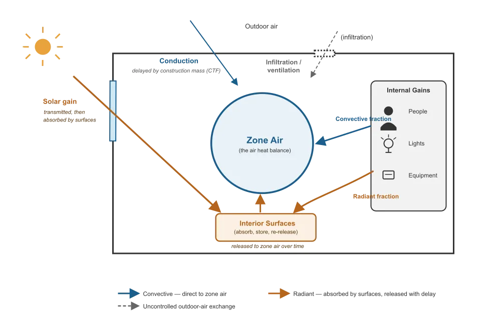
EnergyPlus does not evaluate a load formula once. At every timestep, whether it belongs to a sizing period or to the annual RunPeriod, it solves a heat balance for the outside and inside face of every surface and one for each zone’s air, and the zone’s load is the result of all of them acting together. ASHRAE Handbook—Fundamentals, “Nonresidential Cooling and Heating Load Calculations,” describes the same heat balance method from the load-calculation side.
2.1 Conduction
Walls, roofs, and floors conduct heat according to their constructions. EnergyPlus uses Conduction Transfer Functions (CTFs) by default, which carry a construction’s thermal mass: a heavy wall passes an outdoor temperature swing to its inside face hours later and reduced in size. A wall’s contribution to the load therefore lags the outdoor temperature. Heat conducted to an inside face reaches the zone air by convection from that face and by radiation to the other surfaces.
2.2 Solar gain
Solar radiation is transmitted through glazing (Windows, Shading, and Daylighting) and absorbed by exterior and interior surfaces, which warm and release the heat over time. Where transmitted solar lands inside a zone is set by the Building’s Solar Distribution field: MinimalShadowing places it all on the floor and ignores exterior shading surfaces such as overhangs and fins, FullExterior (the default) calculates exterior shading and places interior beam solar on the floor, and FullInteriorAndExterior also tracks the beam onto whichever interior surfaces it strikes. The WithReflections forms add solar reflected from exterior surfaces. Open the Building from the Building row of the Building Geometry Outliner (Creating Building Geometry).
2.3 Internal gains
People, Lights, ElectricEquipment, and OtherEquipment each split their heat between a convective part, which enters the zone air at once, and a radiant part, which surfaces absorb first and release over time, as they do absorbed solar. The split is set on each object (Internal Loads, Space Types, and Zone Types):
People: Fraction Radiant defaults to 0.30. The Activity Level Schedule Name sets the metabolic rate, from which EnergyPlus splits the heat into sensible and latent parts; Sensible Heat Fraction overrides that split when entered.Lights: Return Air Fraction, Fraction Radiant, and Fraction Visible default to 0, so lighting heat is fully convective unless they are set.ElectricEquipmentandOtherEquipment: Fraction Latent, Fraction Radiant, and Fraction Lost default to 0, so a plug load is fully convective unless they are set.
2.4 Infiltration and ventilation
Infiltration and ventilation exchange outdoor air with the zone. Each carries a sensible load, in proportion to the indoor-outdoor temperature difference, and a latent load, in proportion to the indoor-outdoor humidity difference. The infiltration object’s fields are in Internal Loads, Space Types, and Zone Types; choosing a rate, and how infiltration relates to mechanical ventilation, is in Infiltration, Natural Ventilation and Airflow Networks.
Radiant gains and thermal mass are why a zone’s load rarely peaks at the same moment as its largest single driver. A west zone’s peak cooling hour depends as much on how fast stored radiant heat returns to the air as on when the sun on its glass is strongest.
2.5 Heat balance settings
Two objects under Simulation Parameters in the main object dialog set how the heat balance is solved. A new model has neither, so their defaults apply, and a typical project leaves it that way.
HeatBalanceAlgorithm: Algorithm defaults toConductionTransferFunction.ConductionFiniteDifferenceand the moisture-transfer options are for projects that study phase-change materials or moisture in assemblies.ZoneAirHeatBalanceAlgorithm: Algorithm (defaultThirdOrderBackwardDifference) sets how the zone air equation is solved. Do Space Heat Balance for Sizing and Do Space Heat Balance for Simulation (bothNoby default) calculate a separate load for each Space of a Zone that has more than one (§5.2).
3. Cooling loads
Cooling is the more dynamic of the two loads, because nearly every driver in §2 adds heat at once: conduction whenever it is warmer outside than in, solar gain, internal gains, and infiltration when the outdoor air is warmer or more humid than the zone. They arrive at different times and with different lags, so a zone’s peak cooling hour is a result of the heat balance and cannot be read off the hottest hour of the sizing period. A heavy, west-facing zone can peak well after the hottest hour, as heat stored during the afternoon works out of its walls; a light, east-facing zone with large internal gains can peak near midday, driven by occupancy and equipment more than by its envelope.
Sensible cooling load is the sum of the sensible contributions: conduction, transmitted and absorbed solar, the convective and released radiant parts of internal gains, and sensible infiltration and ventilation gain.
Latent cooling load comes from fewer sources: People, outdoor air more humid than the zone, and any equipment object with a Fraction Latent above 0, such as a process load that releases moisture. The sensible and latent split is a property of the zone’s load, independent of the equipment that serves it. How a coil responds to a given combination is in Air-Side System Fundamentals.
By default Sizing:Zone sizes and reports the sensible load only: its Zone Load Sizing Method defaults to Sensible Load Only No Latent Load, under which latent loads are not used for sizing and are reported as 0 in the sizing results. Sensible Load, Latent Load, and Sensible And Latent Load control the zone’s humidity during sizing and report both loads (Zone-Level HVAC Equipment and Zone Sizing).
Which sizing period and hour govern a zone’s peak cooling load depends on orientation, mass, and internal-gain timing, evaluated across every SizingPeriod:* object in the model (Weather, Climate, and Design Conditions). The HVAC Sizing Summary reports the period and time EnergyPlus selected for each zone (§6.2).
4. Heating loads
4.1 What a heating sizing period removes
A heating sizing period runs the same dynamic heat balance as any other period: EnergyPlus does not switch to a steady-state calculation for heating. What changes is the weather and the schedules, which are set up to represent a near-worst case:
- A heating
SizingPeriod:DesignDayconventionally has a Daily Dry-Bulb Temperature Range of 0, so the whole day sits at the design temperature and the building’s mass has no milder hours to draw on (Weather, Climate, and Design Conditions). - Solar gain contributes little in winter, and a heating design day takes no credit for favorable sun.
- Internal gains are removed by the schedules, not by EnergyPlus. The internal-loads templates in EP3’s library give their
People,Lights, andElectricEquipmentschedules aFor: WinterDesignDayrule of 0 for every hour, and groupSummerDesignDaywith the weekday profile. Heating equipment must recover a zone from a cold spell that falls during an unoccupied period, such as a night, weekend, or holiday shutdown, so no credit is taken for occupant or equipment heat. A schedule without aWinterDesignDayrule falls through to its catch-all rule and may credit occupied-hour gains against the heating load. Model Validation’s Schedules tab checks these design-day values (Schedules).
With solar and internal gains removed, a heating design load is dominated by conduction and infiltration, both driven by the indoor-outdoor temperature difference with nothing to offset them. It is also sensible only, unless the project models humidification.
4.2 Weather-file sizing periods and day types
The WinterDesignDay rule applies only on a day whose day type is WinterDesignDay. A SizingPeriod:DesignDay sets its day type in Day Type. A SizingPeriod:WeatherFileConditionType, the kind every new EP3 model starts with (“Summer Extreme” and “Winter Extreme”, Weather, Climate, and Design Conditions), sets it in Day of Week for Start Day, which defaults to Monday. At that default the extreme week runs Monday through Sunday on each schedule’s ordinary weekday and weekend rules, so the heating sizing credits occupied-hour internal gains on its weekdays, and its governing hour often falls on a weekend morning, when an office’s gains are low.
To size heating with the design-day convention on a weather-file period, set Day of Week for Start Day of “Winter Extreme” to WinterDesignDay, which applies that day type to the whole period, or size against ASHRAE SizingPeriod:DesignDay objects with Day Type WinterDesignDay. The same choice applies to “Summer Extreme” and SummerDesignDay.
4.3 Worked example: a steady-state check of a heating load
With gains removed and no daily swing, a heating design load can be checked by hand. Conduction through each element is U × A × ΔT, and the sensible load of infiltration is ρ × cp × V × ΔT, or 1.08 × cfm × ΔT in IP units (ASHRAE Handbook—Fundamentals, “Nonresidential Cooling and Heating Load Calculations”).
Take a perimeter zone with 40 m² (430.6 ft²) of exterior wall at U = 0.36 W/m²·K (0.0634 Btu/h·ft²·°F), 10 m² (107.6 ft²) of window at U = 2.0 W/m²·K (0.352 Btu/h·ft²·°F), and 0.02 m³/s (42.4 cfm) of infiltration, heated to 21.1°C (70°F) against the Washington Dulles 99.6% heating design dry-bulb of −11.8°C (10.8°F) from Weather, Climate, and Design Conditions. ΔT = 21.1 − (−11.8) = 32.9 K (70 − 10.8 = 59.2°F).
| Component | SI | IP |
|---|---|---|
| Wall | 0.36 × 40 × 32.9 = 474 W | 0.0634 × 430.6 × 59.2 = 1,616 Btu/h |
| Window | 2.0 × 10 × 32.9 = 658 W | 0.352 × 107.6 × 59.2 = 2,245 Btu/h |
| Infiltration | 1.2 kg/m³ × 1,006 J/kg·K × 0.02 m³/s × 32.9 K = 794 W | 1.08 × 42.4 × 59.2 = 2,709 Btu/h |
| Total | 1,926 W | 6,570 Btu/h |
(1 W = 3.412 Btu/h: 1,926 W × 3.412 = 6,572 Btu/h; the IP column rounds each line separately.)
EnergyPlus’s Calculated Design Load for such a zone (§6.2) will be close to this figure but not equal to it: EnergyPlus calculates surface convection and radiation at each timestep, includes floors, roofs, and heat exchanged with adjacent zones, and evaluates infiltration at the outdoor air density. A result far from the hand figure points to a missing or doubled surface, an infiltration rate in the wrong units, or internal gains credited on the heating sizing period (§4.2).
5. From design day to annual profile
5.1 The annual run
The annual RunPeriod solves the same heat balance at every timestep of the simulated year. Only the inputs differ: recorded weather-file conditions in place of a design condition, and each schedule’s weekday, weekend, and holiday values in place of its design-day rules. The result is a sensible and latent load for each zone through the year, the annual load profile.
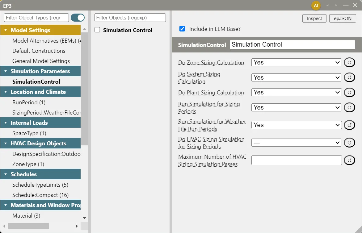
Whether the sizing periods and the annual run take place is set in SimulationControl (Simulation Parameters in the main object dialog). EP3 creates every model’s SimulationControl with Do Zone Sizing Calculation, Do System Sizing Calculation, Do Plant Sizing Calculation, Run Simulation for Sizing Periods, and Run Simulation for Weather File Run Periods set to Yes (Weather, Climate, and Design Conditions). With Run Simulation for Sizing Periods at Yes, EnergyPlus also simulates each sizing period with the sized equipment, so the time-series results hold the sizing periods as well as the year (§6.3).
5.2 Coincident and non-coincident peaks
A building or system peak is not the sum of each zone’s peak. Zones facing different directions or running different schedules peak at different hours, so equipment serving several zones sees less than the sum of their individual worst hours. EnergyPlus offers the choice at two levels:
- Spaces in a Zone. When a Zone holds more than one Space (Spaces and Zones),
Sizing:Zone‘s Type of Space Sum to Use choosesCoincident(the default: the Spaces’ loads summed at the same moment) orNonCoincident(each Space’s peak summed whenever it occurs).NonCoincidentrequires Do Space Heat Balance for Sizing = Yes inZoneAirHeatBalanceAlgorithm(§2.5). - Zones on an air loop.
Sizing:System’s Type of Zone Sum to Use choosesNonCoincident(the default) orCoincidentfor the zones the system serves.
Zone-Level HVAC Equipment and Zone Sizing and Air Loops, Branches, and Nodes cover these fields.
6. Seeing the loads in EP3
6.1 What a run reports by default
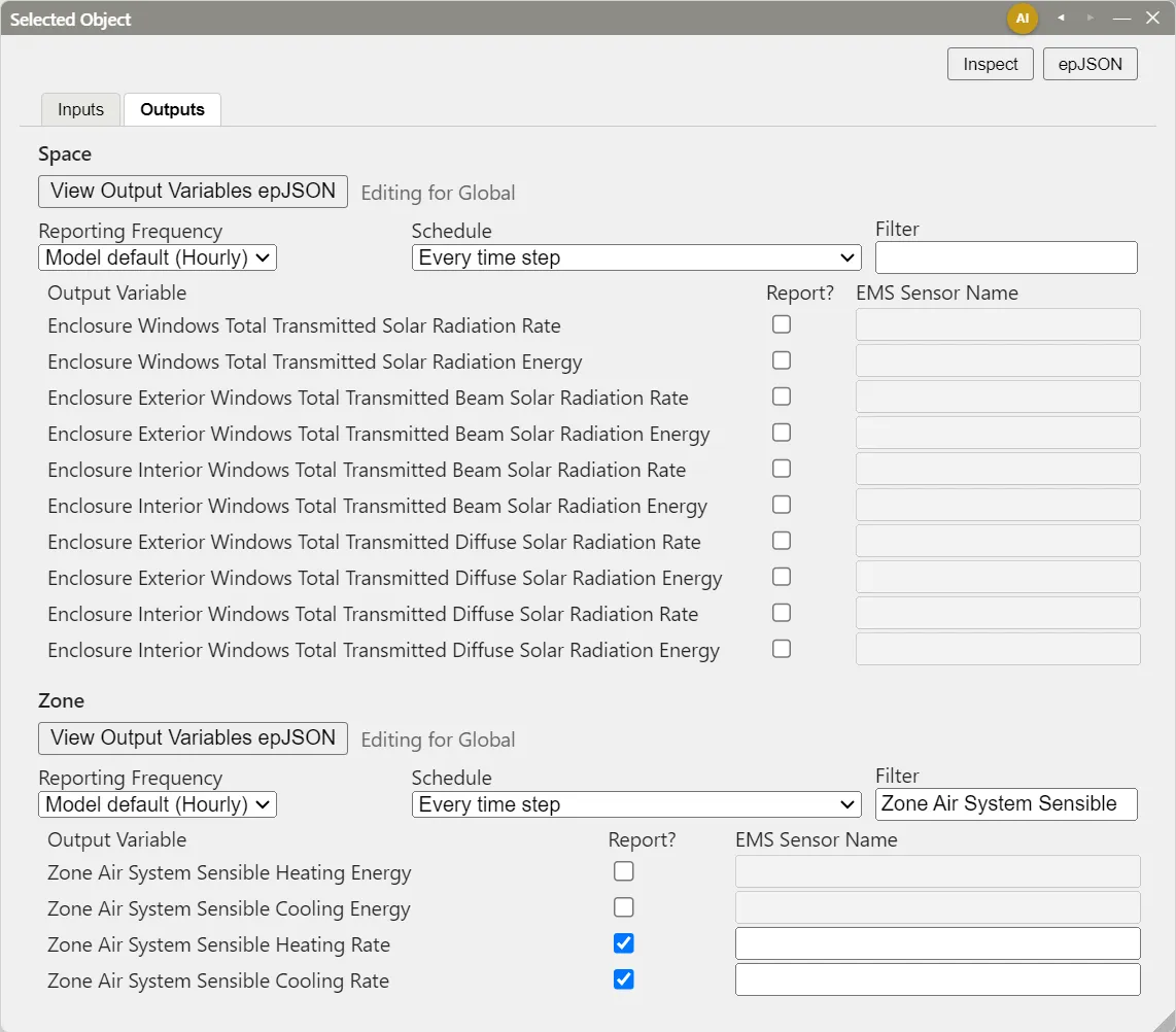
Every simulated run requests EnergyPlus’s AllSummary tabular reports, so the peak loads of §6.2 need no setup. Most time-series loads do. Each export requests the outdoor dry-bulb, wet-bulb, and dew-point temperatures and each zone’s Zone Mean Air Temperature, at the model’s Default Reporting Frequency for Output:Variable (Hourly unless changed in General Model Settings, The EP3 Interface and Model Settings). For the unmet hours analysis it also requests each zone’s thermostat setpoints, occupant count, and Zone Air System Sensible Heating Rate and Cooling Rate, and each air loop’s on/off status, hourly (or by timestep when the model reports by timestep), and each zone’s setpoint-not-met times monthly. Request other load variables before you simulate, in either of two places:
- A zone’s Outputs tab. Select a Space and open the Selected Object dialog’s Outputs tab, which has a Space sub-tab and a Zone sub-tab for the variables of each. Type in Filter to find a variable, tick Report?, and choose a Reporting Frequency if the model default does not suit. With several Spaces selected, EP3 offers to make the change for all of them.
- View Building Data. The Building Geometry Outliner’s View Building Data button opens a picker of every surface, window, zone, and space variable; ticking a variable’s frequency requests it for every object in the next run.
Load variables on the Zone include:
| Variable | What it reports |
|---|---|
| Zone Air System Sensible Cooling Rate, Zone Air System Sensible Heating Rate | The sensible cooling or heating the zone’s HVAC delivered to the zone air |
| Zone Predicted Sensible Load to Setpoint Heat Transfer Rate | The sensible load needed to bring the zone to setpoint, before the equipment runs (positive for heating, negative for cooling) |
| Zone Windows Total Transmitted Solar Radiation Rate, Zone Windows Total Heat Gain Rate | Solar entering through the zone’s windows, and the windows’ total heat gain |
| Zone Infiltration Sensible Heat Gain Energy, Zone Infiltration Sensible Heat Loss Energy | Infiltration’s sensible contribution |
| Zone Total Internal Total Heating Rate, Zone Total Internal Latent Gain Rate | The zone’s internal gains |
A zone served by ZoneHVAC:IdealLoadsAirSystem reports its load independent of any equipment performance, as Zone Ideal Loads Zone Sensible Cooling Rate, Zone Ideal Loads Zone Latent Cooling Rate, and the matching heating variables (Zone-Level HVAC Equipment and Zone Sizing). Viewing and Interpreting Results covers requesting outputs in full.
6.2 Peak loads: the HVAC Sizing Summary
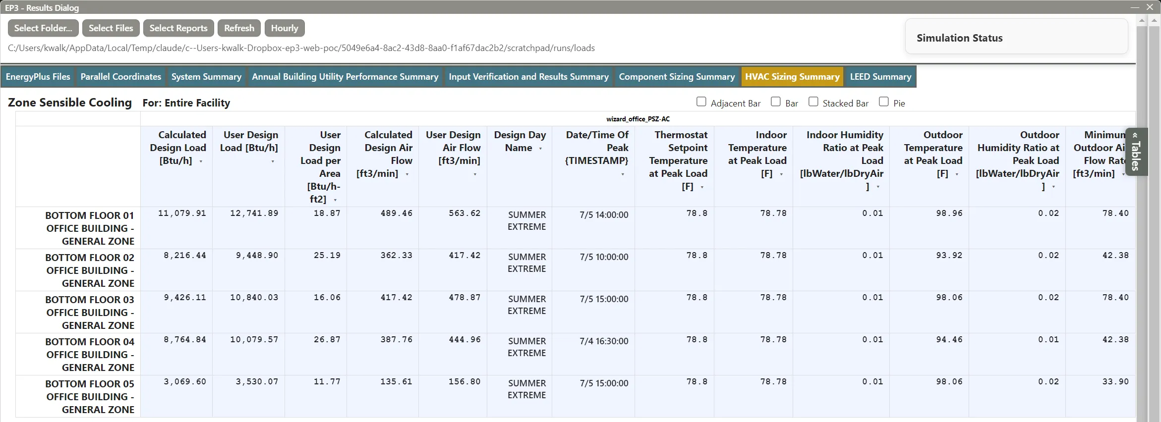
After a run, View Results opens the Results dialog (Viewing and Interpreting Results). Its default tabs include Component Sizing Summary, which lists every autosized value of every component, and System Summary, with its Time Setpoint Not Met table. The zone loads are in the HVAC Sizing Summary report, which is not shown by default: click Select Reports, expand HVAC Sizing Summary, tick Zone Sensible Cooling and Zone Sensible Heating, and click Update. Reset To Default returns to the default selection.
Each table has a row per zone with these columns (Output Details: HVAC Sizing Summary):
| Column | Meaning |
|---|---|
| Calculated Design Load | The peak load from the heat balance, before any sizing factor |
| User Design Load, User Design Load per Area | The load after the zone’s sizing factor, and that load per floor area |
| Calculated Design Air Flow, User Design Air Flow | The design airflow before and after the sizing factor |
| Design Day Name, Date/Time Of Peak | The sizing period and the time the peak occurred |
| Thermostat Setpoint Temperature at Peak Load, Indoor Temperature at Peak Load, Indoor Humidity Ratio at Peak Load | Zone conditions at the peak |
| Outdoor Temperature at Peak Load, Outdoor Humidity Ratio at Peak Load | Weather at the peak |
| Minimum Outdoor Air Flow Rate, Heat Gain Rate from DOAS | The zone’s design outdoor air, and the heat a dedicated outdoor air system adds or removes |
With EP3’s default sizing periods, Design Day Name shows the SizingPeriod:WeatherFileConditionType that governed (SUMMER EXTREME or WINTER EXTREME), and Date/Time Of Peak the day and hour within it.
Worked example: the sizing factor. User Design Load = Calculated Design Load × the zone’s sizing factor (Sizing:Zone’s Zone Cooling Sizing Factor or Zone Heating Sizing Factor; when blank, the factor in Sizing:Parameters, which defaults to 1.0). A zone with a Calculated Design Load of 3,149.40 W and a Zone Cooling Sizing Factor of 1.15 shows 3,149.40 × 1.15 = 3,621.81 W as its User Design Load. In IP units, 3,149.40 W × 3.412 = 10,746 Btu/h and 10,746 × 1.15 = 12,358 Btu/h, which matches 3,621.81 W × 3.412 = 12,358 Btu/h. A User Design Load per Area of 34.83 W/m² (11.04 Btu/h·ft²) places the zone’s floor area at 3,621.81 / 34.83 = 104.0 m² (1,119 ft²).
The HVAC Sizing Summary gives each zone’s peak but not what made it up. To see each peak broken into conduction, solar, internal gains, infiltration, and the rest, add an Output:Table:SummaryReports object (Output Reporting in the main object dialog) with Report Name AllSummaryAndSizingPeriod: it adds the Zone, AirLoop, and Facility Component Load Summary reports to everything AllSummary gives. EP3 adds its AllSummary request only when the model has no Output:Table:SummaryReports object, so the object you add must include every summary report you want. These reports repeat the zone sizing calculation, which lengthens the run. For the annual run, the Sensible Heat Gain Summary report (part of AllSummary) breaks the building’s sensible gains into the same components, for the year and at the peak cooling and heating times (Output Details: Sensible Heat Gain Summary).
6.3 The annual profile: the time-series viewer
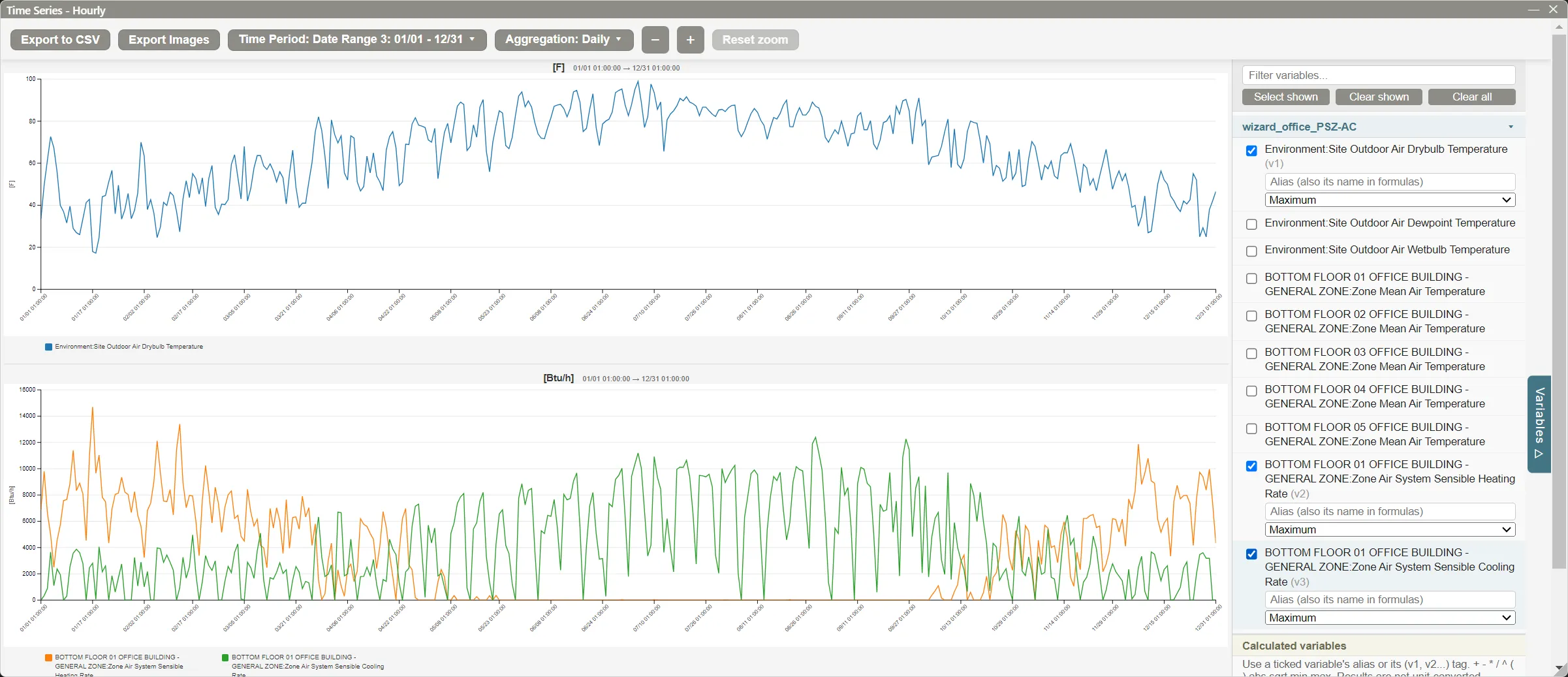
The Results dialog has one button per frequency the run reported (Hourly, for example), each opening the Time Series viewer for that frequency. Tick a zone’s load variables in the panel on the right to chart them. Time Period lists the date ranges in the file: EnergyPlus writes the sizing periods and the run period one after another, and EP3 starts a new range wherever the dates jump, so each sizing period and the annual run each have an entry. Aggregation rolls the hours up to days or months, and its value type chooses the sum, average, minimum, or maximum. Drag across a chart to zoom to a span; double-click to show the whole period again.
Charting a zone’s Zone Air System Sensible Cooling Rate for the run period beside Site Outdoor Air Drybulb Temperature shows how closely the load follows the weather and how closely it follows the occupancy schedule. Viewing and Interpreting Results covers the viewer in full.
6.4 Where in the building: View Building Data
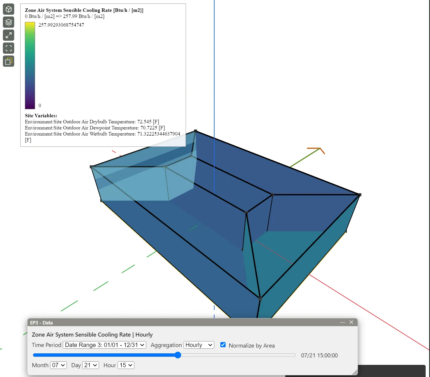
View Building Data in the Building Geometry Outliner colors the 3D view by a result. In its picker, click a variable’s frequency button (shown once the active EEM’s last run has that variable) to open the EP3 - Data dialog: choose a Time Period, an Aggregation and value type, and move the time slider to a month, day, and hour. Normalize by Area divides each zone’s value by its floor area, so a small zone and a large one with the same load intensity show the same color. Coloring zones by Zone Air System Sensible Cooling Rate at a summer afternoon hour, normalized by area, shows which orientations carry the highest cooling load per unit floor area at that hour. Viewing and Interpreting Results covers the display.
6.5 Whether the system met the loads
The default Time Setpoint Not Met table, on the System Summary tab, gives the hours each zone’s temperature was outside its heating or cooling setpoint during the annual run, for all hours and for occupied hours. Hours here mean the sized equipment did not meet the loads at those times, either because the sizing periods did not represent the year or because a sizing input limited the equipment. Model Troubleshooting and Quality Assurance covers tracing unmet hours.
7. How the loads feed HVAC sizing
The sizing flags in SimulationControl (§5.1) decide whether Sizing:Zone, Sizing:System, and Sizing:Plant run. When they do, they consume the loads this chapter describes: each zone’s peak sensible (and, when the Zone Load Sizing Method includes it, latent) load, with the sizing period and time it occurred. Nothing about the load calculation is set on Sizing:Zone. Its fields (design supply air conditions, sizing factors, outdoor air) turn that peak into a design airflow and capacity, which Zone-Level HVAC Equipment and Zone Sizing covers. A ZoneType with a thermostat carries a Sizing:Zone for every zone of that type (Internal Loads, Space Types, and Zone Types).
A zone’s calculated peak load and the capacity of the equipment that serves it are related figures, not the same one. Sizing factors, fan heat, outdoor air, and coincidence at the system level all lie between them, so an equipment output variable will not reproduce the zone’s Calculated Design Load.
8. Common pitfalls
A custom internal-loads schedule without a WinterDesignDay rule. The library templates zero occupancy, lighting, and equipment on the heating design day through an explicit rule (§4.1). A hand-built or imported schedule without one falls through to its catch-all rule and can credit a full day of occupied gains against the heating load, understating it for the unoccupied cold spell the convention protects against.
Expecting the WinterDesignDay rule to apply to the default sizing periods. “Winter Extreme” and “Summer Extreme” run on ordinary day types unless Day of Week for Start Day is set to a design day type (§4.2).
Looking for latent loads in the sizing results with the default Zone Load Sizing Method. At Sensible Load Only No Latent Load, latent loads are reported as 0 and do not size anything (§3).
Assuming the hottest sizing period gives every zone’s peak cooling load. Orientation, mass, and internal-gain timing can move a zone’s peak to another hour or another sizing period (§3). Read Design Day Name and Date/Time Of Peak in the HVAC Sizing Summary.
Treating the zone load and the equipment capacity as the same number. The load is an input to sizing; the installed capacity follows from it through sizing factors and system-level effects (§7).
Leaving out infiltration because mechanical ventilation is modeled. Infiltration is a separate, uncontrolled outdoor-air path that adds to both heating and cooling loads whatever the mechanical ventilation does (Infiltration, Natural Ventilation and Airflow Networks).
Simulating before requesting the load variables. Only outdoor temperatures and zone mean air temperatures are reported by default (§6.1). Request load variables before the run.
This handbook is also built into EP3 (Help), where its EnergyPlus links open the EnergyPlus Reference. Technical specifications · Book a demo