Creating Building Geometry
1. Overview
EP3 builds a building’s geometry one floor at a time. You draw a Floor, and each closed area on it becomes a Space. The Space boundaries are grown up into wall and roof surfaces: in Automatic mode, the default for a new model, EP3 does this as you draw; in Manual mode it is a separate step (§1.2). Every wall, floor, and roof face that results is exported as a BuildingSurface:Detailed object, and every window or door as a FenestrationSurface:Detailed object, all derived from the geometry you draw.
EP3 creates one Zone per Space, so a model can be simulated as soon as its geometry and constructions are complete. You can combine several Spaces into one Zone, or change the assignment in other ways, at any time; Spaces and Zones covers that step and thermal-block strategy. This chapter stops at Space creation.
EP3 can also make the Building, its Floors, and its Spaces from a map or an outline file (Buildings and Surroundings from Maps).
EP3 can also bring in an existing building’s surfaces by importing an EnergyPlus IDF or epJSON file, including one written by a BIM-to-EnergyPlus tool. Importing EnergyPlus Files covers that path.
1.1 Collections and the Building Geometry Outliner
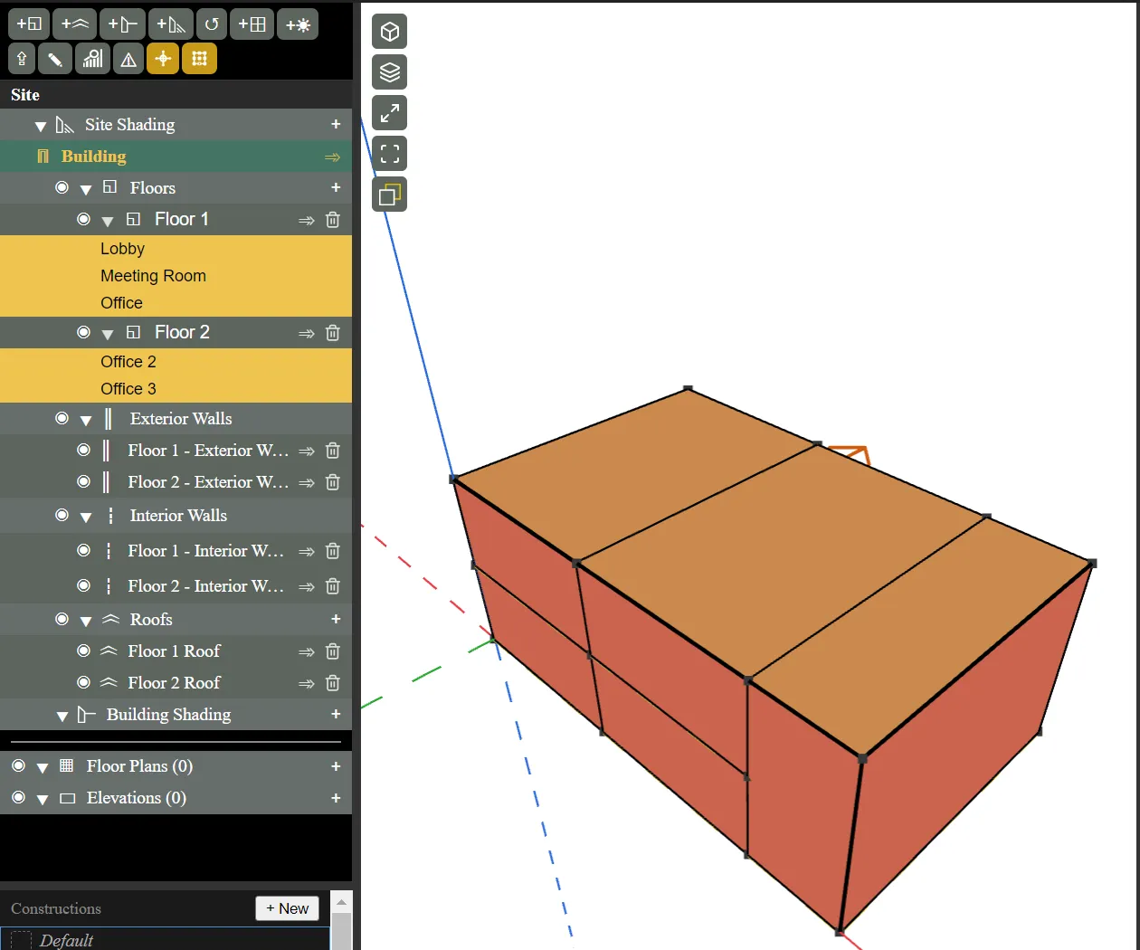
Geometry lives in collections, each a row in the Building Geometry Outliner: the Building, its Floors, each floor’s Exterior Walls and Interior Walls, Roofs, Building Shading, and Site Shading. Drawing happens inside one collection at a time, the active collection:
- Double-click a floor, wall group, roof, or shading row (in the outliner or the 3D view) to enter it and open it in the Selected Object dialog. The ⇒ button on a row enters it too; the one on the Building row returns to the whole site.
- The eye button hides or shows a row in the 3D view. Hiding a floor also hides its background drawings.
- Toggle X-ray (V) draws every face semi-transparent, and Isolate active context (Shift+R) hides everything outside the collection you are working in. Isolating a new, empty shading collection leaves nothing to show, so the building seems to disappear; switch isolation off to see it again.
1.2 Automatic and Manual mode
A model is in one of two modes, shown by the Mode button at the top of the 3D view: Automatic or Manual. A new model starts in Automatic, including one made with the Model Wizard or by tracing a drawing. An opened file keeps the mode it was saved in, and a file saved by an older version of EP3, which had no mode, opens in Manual.
Automatic keeps the building up to date as you draw. You draw and edit Floors and their Spaces, and EP3 keeps everything derived from them current after each edit, without a separate step:
- The exterior and interior walls follow the Floors’ space boundaries, up to each Space’s ceiling, with the walls between a taller Space and a lower roof filled in.
- Each Floor with nothing above it has a roof, flat by default. A pitched roof you make is the Floor’s roof and is rebuilt when the Floor changes (§6).
- The ground: a Grade Elevation splits walls where they meet it, and the pieces below it become ground-contact surfaces.
- Faces are matched to the Spaces they border, and constructions are taken from the defaults in this order: the face’s own paint, then its Space, its Space Type, the wall group or roof, and the model’s default constructions (Constructions and Materials).
While EP3 works out the Space matching after an edit, Updating building… shows beside the Mode button. While you are in an isolated Floor, its update waits until you leave it or turn isolation off, and a short note says so.
Because the walls follow the Floors, Automatic locks the edits that would change a wall’s shape: moving, rotating or push/pulling a wall’s outline, erasing its outline or a cut edge, and deleting a face. The Mode button flashes and the status line says “Automatic mode: walls follow the Floors. Switch to Manual to change their shape.” Still allowed are painting (including Adiabatic and Air Boundary), lines drawn across a wall to divide it, and placing, moving, copying and resizing windows and doors. Roofs and Floors can be edited freely; editing a roof’s profile, or making a dormer, makes that roof custom, and the walls still follow it. A custom roof is marked in the outliner, and deleting it puts the Floor back to a flat roof. Grow Walls, Refresh Surface Matching, Assign Space, and the ✕ that removes a Space from a face are hidden, because EP3 does that work itself. Select a wall or roof and its Selected Object dialog says which kind it is, for example “Automatic wall: follows Floor 1”.
Manual is the mode in which you build the walls yourself with Grow Walls (§5), refresh the matching, and assign Spaces to faces by hand.
Switching. Click the Mode button.
- Automatic to Manual opens a short Switch to Manual dialog first. It says that the walls and roofs stop following the Floors and the building stays exactly as it is until you use Grow Walls, that you can switch back to Automatic later, and that one undo reverts the switch. Click Switch to Manual to switch, or Cancel to change nothing. After the switch the geometry is unchanged, the lines and paint you added become ordinary edges and paint, and the Manual tools come back.
- Manual to Automatic opens the Switch to Automatic dialog first. It explains that the building is rebuilt from the Floors: edges inside a wall or roof become your own lines, paint becomes anchors on the walls, and roofs you drew or edited stay custom. A summary says what the switch changes, for example “The switch changes 12 faces, 4 hand assignments”, or “Nothing in the model changes shape.” Below it are lists of the faces reshaped, removed or added, the paint that cannot be placed, the windows and doors deleted or sliced, the hand-assigned Spaces that are dropped (Automatic matches Spaces itself), and the roofs that become automatic or stay custom. Click a row to frame it in the 3D view. Switch to Automatic applies it as one undo step; Cancel changes nothing.
Some behaviours worth knowing in Manual mode:
- Grow Walls leaves no strays. Each regrow first removes any leftover window-like faces and lines that border no face, so repeated regrowing does not accumulate stray geometry.
- Creating a pitched roof over a Floor whose ceiling height is set below the roof’s top asks Extend the walls to the roof? (§6.2). Automatic mode never asks, because the walls always meet the Floor’s roof.
- Regenerate… works on pitched roofs in both modes (§6.3).
- A window sized by a percentage stays in the rectangular part of a wall with a sloped top, and keeps its
OpeningType(§7.1).
2. Building orientation (North Axis)
North Axis is a field of the Building, in degrees clockwise from true north (default 0). Double-click the Building row to open it in the Selected Object dialog. The Model Wizard’s Building North Axis writes the same field.
Setting North Axis does two things: it sets EnergyPlus’s North Axis for solar calculations, and it rotates the building (every floor, wall, roof, and window) in the 3D view. You can set or change it at any time without redrawing anything. North Axis can also differ by EEM, which makes it a natural way to compare orientations of the same building (Energy Efficiency Measures (EEMs)).
Floors, walls, and background drawings are positioned in the building’s own (rotated) coordinates. When you will be positioning background drawings, it is easiest to draw and position them with North Axis at 0 and set the rotation afterward.
3. Adding and configuring a floor
Click Add Floor (the first button in the outliner’s toolbar) to add a floor. The New Floor prompt asks how to make the floor under Choose method:: Create from Scratch for an empty floor, Copy Existing Floor (offered once a floor has a space) to start from a copy of another floor’s spaces and geometry, or Generate from Floorplan to make the floor and its spaces from a CAD drawing (Floors and Windows from CAD Drawings). It then asks for the floor’s Ceiling height (floor to floor), Floor multiplier, and Starts at, the elevation of its bottom. Starts at defaults to the top of the highest floor, and Ceiling height to that floor’s ceiling height. A Floor multiplier above 1 makes a stack of floors as the Model Wizard does: two or three floors, or a bottom, a multiplied middle, and a top floor (The Model Wizard). The floors of a stack are linked and share one plan (§3.3). A new floor is named Floor 1, Floor 2, and so on; rename it in its outliner row or its dialog.
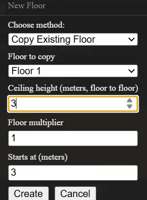
3.1 Floor fields
Double-click a floor to open it in the Selected Object dialog:
- Floor Height Calculation Method — Floor or Roof Above (the walls rise to the next floor slab or roof above) or Specify Ceiling Height. With Floor or Roof Above, a second field chooses which floor or roof sets the height; Auto uses the nearest one above. The floor’s own roof is offered when it is pitched, so the walls rise to its underside; a flat roof of its own is not, since it sits at the height it would set.
- Ceiling Height — the height used with Specify Ceiling Height. It is offered alone when nothing is above the floor.
- Floor Multiplier — default 1; see §3.2. On a linked floor the field shows the group’s total number of storeys (§3.3).
- Elevation — the floor’s height above the model origin. Changing it moves the floor’s geometry, its wall groups, and its background drawings together.
- Construction — the construction every surface of the floor’s slab uses, unless a surface is painted with another (§7.3).
The dialog also has buttons for this floor alone: Interior Walls for Floor, Exterior Walls for Floor, Create Flat Roof or Ceiling, Create Pitched Roof…, and Re-Number Spaces.
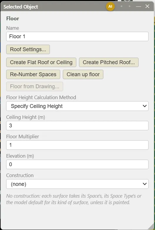
Walls grow from a floor up to the next object above it (another floor’s slab, or a roof) or to the height these fields set, whichever comes first. Floor or Roof Above suits most floors. Specify Ceiling Height suits a building’s top floor, which has nothing above it, and a floor whose walls should rise past where a floor above would stop them: raising a floor’s ceiling height past the floor above, where no floor is drawn over it, makes that area a double-height space. §10 uses this to build a two-story atrium.
3.2 Floor Multiplier and copying floors
There are two ways to model several similar floors:
- Floor Multiplier is EnergyPlus’s repeat-simulation shortcut. Above 1, every
Zoneon the floor gets that multiplier: EnergyPlus simulates the floor once and multiplies the result, and no geometry is added. A Zone’s own multiplier, if set, multiplies the floor’s: a Zone with multiplier 2 on a floor with multiplier 5 is simulated as 10. Use it for a tower’s identical floors. - Copy Existing Floor (§3) duplicates the floor’s geometry and spaces, names included. Use it when a floor is similar to another and will diverge from it. Start with the building’s most common floor and copy it up or down for the others, so that exterior walls and shared interior walls line up.
3.3 Linked floors
A Floor multiplier above 1 in the New Floor prompt makes a bottom, a middle and a top floor (named, for a stack called Typical, Typical Bottom, Typical Middle and Typical Top) that are linked: they share one plan. The multiplier is the number of storeys the stack stands for in all; the middle floor stands for the storeys between the bottom and the top. A multiplier of 2 makes a bottom and a top floor. In the outliner a link symbol marks each floor of a linked stack, and while you are on one of its floors the 3D view shows a banner such as “Editing Typical: changes apply to all 3 linked Floors.”
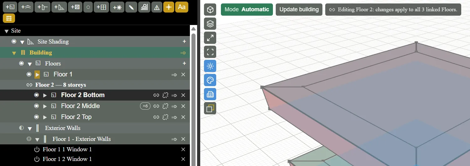
What the floors share. Edit any floor of the stack and the others follow, in the same undo step:
- The plan: its edges, its corners, and the Spaces they enclose.
- Space names and Space Types.
- Every Space input: the construction fields, the Envelope, Lighting, and Ventilation Space Types, Space Function, Is Vestibule, ceiling height, and the rest. A Space’s name keeps its floor prefix.
- Windows, doors, wall paint, and wall lines you draw. A window added to one floor appears at the same place on the others.
- Daylight sensors and each Space’s daylighting settings. A sensor added, moved, edited, deleted, or turned on or off in an EEM on one floor does the same on the others; each floor’s sensors sit in that floor’s Spaces. Sensor names stay unique, so each floor’s sensors have names of their own.
Each floor keeps its Zones and their settings, so HVAC connections, thermostats, and other Zone settings can differ between the floors of a stack.
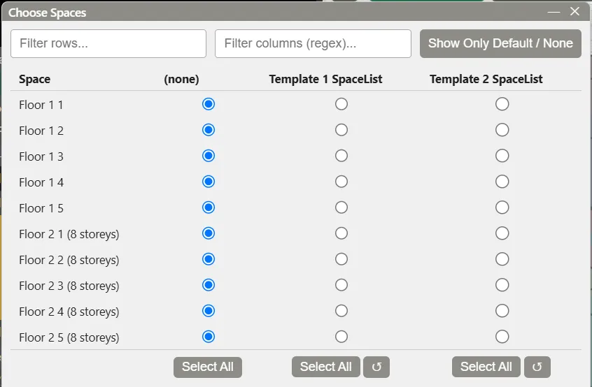
In the Choose Spaces picker and on a Space Type’s Spaces tab, a linked Space is one row, such as “Typical Office 1 (8 storeys)”; choosing it assigns the Space on every floor of the stack. Space Types matched by name (Name mode, Internal Loads, Space Types, and Zone Types) follow each floor’s Space names, so they can differ between the floors.
Multiplied storeys. In a stack of four or more, the storeys the middle floor stands for are drawn as faint copies of its walls, windows and outline, and hovering over one names it (“Typical Middle ×6: storey 4 of 8 (part of the multiplier)”). They cannot be selected and are not exported. An elevation drawing wrapped on the building covers them too. Show multiplied storeys on the View toolbar turns them off.
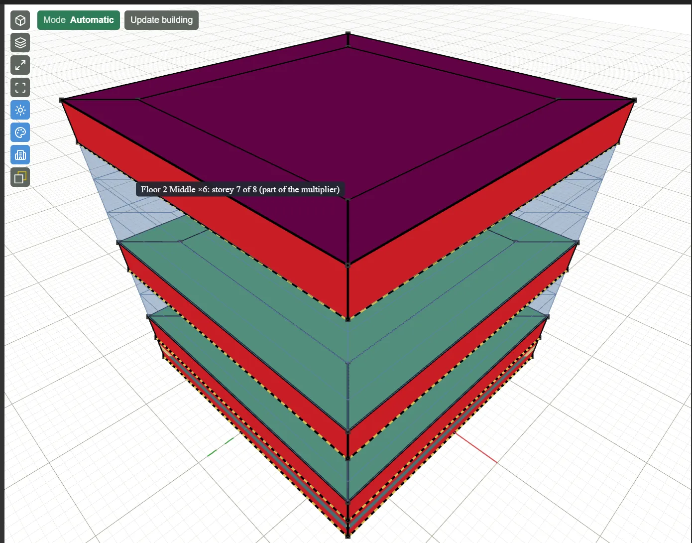
Other stacks that are linked. The Model Wizard’s floors and each building’s run of storeys from a map (Buildings and Surroundings from Maps) are linked the same way. An imported EnergyPlus file’s floors are linked when they form the same stack EP3 makes (a bottom floor, a middle floor with the multiplier, and a top floor at the usual storeys, or two or three plain floors) and linking them changes nothing in the export (Importing EnergyPlus Files). A multiplier typed into an unlinked floor’s dialog stays a plain multiplier.
Where a shared window does not appear. A window stays off a floor where its wall is an interior wall, where the wall’s construction is Adiabatic or an Air Boundary, or where the wall is below grade on that floor. On that floor the window is drawn as a dashed red outline; hover over it to see the reason. The window comes back as soon as the wall allows it, for example when a neighboring floor or block no longer makes it an interior wall. When a window is added and some floors cannot show it, a message in the status line names the floors and the reason.
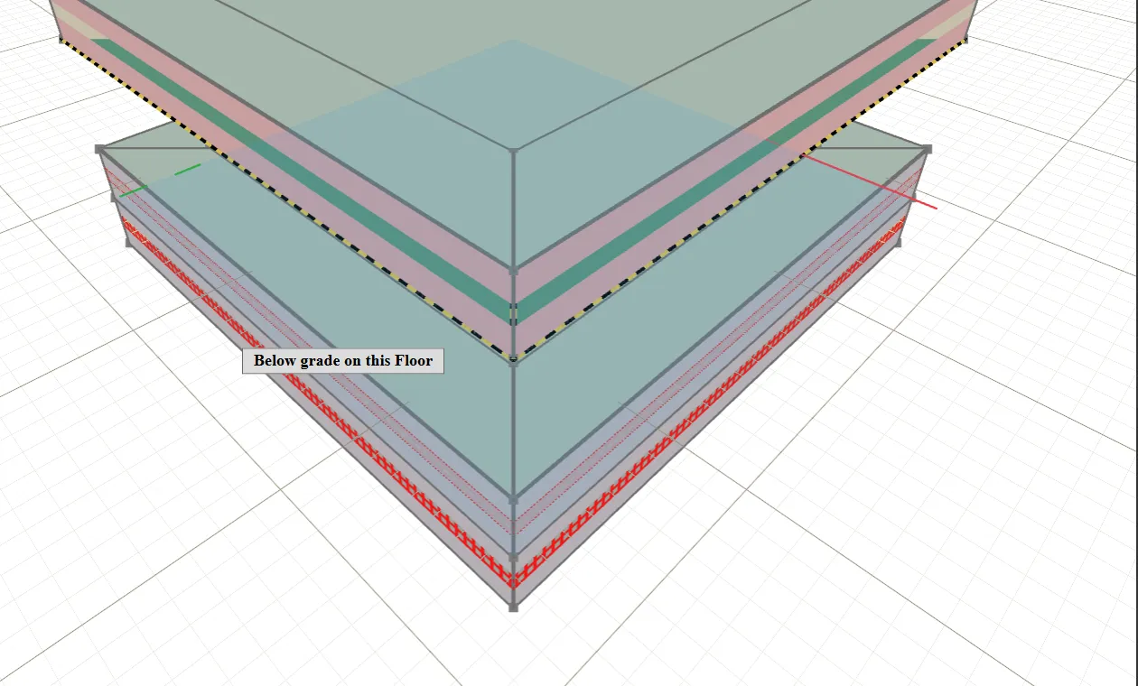
Below-grade windows. A window on a wall below grade is drawn in red with a hatch. It is not exported to EnergyPlus.
Fields on a linked floor. Floor Multiplier, Ceiling Height and Starts at on any floor of the stack apply to the stack as a whole, and the dialog says so: the multiplier field is labeled as the linked group’s total and a note lists the bottom, middle and top counts. Changing the total, the ceiling height or Starts at lays the three floors out again. Floors above the stack that sit on it move with it.
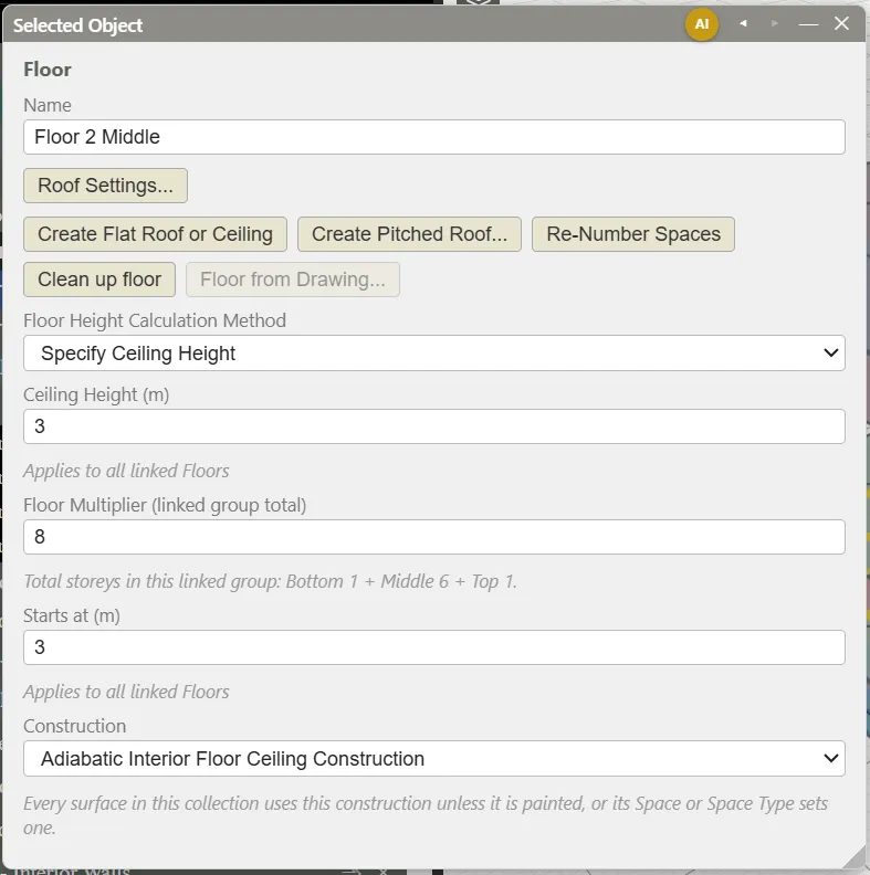
Unlink. To work on one floor alone, click Unlink on its row in the outliner. The floor keeps a copy of the plan as it is, becomes an ordinary floor, and leaves the group; the other floors stay linked. A floor that is deleted is unlinked first, and the others keep the plan. Copying a floor that has a multiplier makes new floors linked to each other, not to the floor they were copied from.
The Windows from Elevations tool treats a linked stack as one: it matches the elevation drawing against the shared plan, uses every storey of the drawing to decide each window’s size, and places the windows once so that every floor shows them (Floors and Windows from CAD Drawings).
4. Drawing space boundaries
Enter a floor to draw on it. Drawing inside a floor stays on the floor’s plane. View Top (Shift+T) gives a top-down view, and the floor grid appears; its toolbar buttons show or hide the grid and turn snapping to it on or off, and Building Geometry Grid Spacing in General Model Settings sets its spacing.
The drawing tools in the top toolbar work as in most 3D modeling programs:
- Line draws connected edges; Rectangle draws a rectangle from two corners.
- Move, Rotate (Q), and Push/Pull edit geometry; Tape Measure measures; Erase removes edges; Select selects; Orbit turns the view.
- Points snap to vertices, midpoints, and edges, and to the grid when grid snapping is on.
- Typed values. While drawing, type a length and press Enter to set it exactly: a single number for Line or Move (a distance along the direction you are pointing), or two numbers for Rectangle (
50,30or50x30). Values are in the display units, so20is 20 ft in IP. The value appears in a box at the top right of the 3D view as you type. While you move, the same box shows the distance moved so far, for example “Distance 3.25 m”. - Arrays. Hold Ctrl while moving to copy instead. Right after the copy, type a count followed by
xand press Enter to repeat it:5xmakes five copies in all, each the same distance on from the one before, for evenly spaced windows or rooms. The copies are one undo step.
Every closed loop of edges becomes a Space, with no separate step. New spaces are numbered (01, 02, and so on); rename one by editing its name in the outliner, or renumber a floor’s spaces with Re-Number Spaces. Redrawing or nudging a boundary keeps the Space (its name and everything assigned to it) as long as the new area overlaps the old one.
Looking down at a floor, each Space shows its name at a steady, readable size wherever it fits inside the Space; zoom in to bring back the names of smaller rooms. The Aa button on the outliner’s toolbar hides or shows the names. Move the cursor over the plan and the outliner highlights the row of the Space under it, so you can find a room’s name without anything covering your work.
To rename several spaces at once, select their faces on the floor, right-click, and choose Rename Spaces. The new name keeps each space’s leading number (“03 Break” becomes “03 Office”). When templates are matched by name, the name can be picked from the model’s SpaceType names, so the renamed spaces take that template. When templates are assigned by hand (Selected Template mode), the same menu offers Assign Space Type, which assigns the selected spaces to one SpaceType, or to none.
To remove part of a floor, erase edges: drag the Erase tool across them. Erasing an edge between two spaces merges them into one; erasing the outer edges around a space removes it. When an edit leaves a face less than 5 mm wide, EP3 joins it to the face beside it or removes it, and the status line says so, for example “Your edit left a strip under 5 mm wide in Floor 1. EP3 joined it to the face beside it.” The Draw Mode button in the outliner’s toolbar switches between Spaces, where you draw and erase space boundaries, and Geometry, where boundary edges are locked and only interior subdivisions can be drawn or erased.
Split lines. EP3 divides a floor’s surfaces where what lies below changes: a wall of the floor below, or the outdoors beside a lower roof. In Spaces mode these lines show dotted and stay out of your way: you can’t select, snap to, move or erase them, and a space boundary they meet still selects, moves and erases as one edge. Clicking a floor selects the whole space. After each change, EP3 redraws the split lines from what is below, so they always match the building. To give one part of a space a different construction, paint it with the Paint tool, which still paints the part you click. Switch to Geometry mode to see and select every line and part separately. Lines you draw yourself in Geometry mode inside a space stay solid and selectable.
Internal Loads, Space Types, and Zone Types covers giving spaces their loads through templates.
5. Generating walls
In Automatic mode (§1.2) the walls are generated for you and kept current as you draw, and the buttons described here are hidden. The rest of this section describes Manual mode.
Once a floor’s space boundaries are drawn, generate its walls:
- For the whole model, click the button in the outliner’s toolbar that generates exterior and interior walls for every floor. It is one undo step.
- For one floor, use Interior Walls for Floor or Exterior Walls for Floor in the floor’s dialog.
Either way, EP3 grows the floor’s space-boundary edges up to the height from §3.1, cuts the walls where they meet floor slabs and roofs, and matches each face to the Space or Spaces it borders. Generating walls also adds a flat roof over any floor with nothing above it (§6). If a floor already has walls, they are replaced in place, keeping their constructions. A window no longer wholly on a wall is cut at the wall face edges into one window per face, and a window left with no wall is deleted; the status bar reports both. The same happens when a roof is created, a dormer is made, surface matching is refreshed, or a floor’s elevation changes. A cut window’s pieces keep its construction, shading, and on/off settings, but not its OpeningType or EEM sizes.
Refresh Surface Matching, in the outliner’s toolbar, recuts every wall and roof against the current geometry and matches the faces to Spaces again, without regenerating the walls. Use it after drawing a wall or a roof by hand, or after editing a roof that spans several rooms. Afterwards, any face that still does not match shows in the unexpected adjacency highlighter (§11).
5.1 Surface and window names
Every wall, roof, floor, ceiling, window, and door has one name, used by the dialogs, Model Validation, the results, Atlas, and the export. EP3 names it after its Space (with the floor’s name), its kind (Wall, Roof, Floor, Ceiling, Window, or Door), and the first number that Space’s surfaces of that kind do not use: “Floor 1 Office Wall 3”, “Floor 1 Office Window 1”. An interior wall has one name on each side, one per Space.
- Adding, removing, or moving other surfaces does not change a name, and neither does regenerating walls or refreshing surface matching: a rebuilt face keeps the name of the face it replaces.
- Renaming a Space or floor updates its surfaces’ names, keeping their numbers. A window moved into another Space, or a window that becomes a door, is named again.
- To rename a surface or window, edit the Name at the top of its Selected Object dialog. A name another surface or window already has gets a number added (” 2”). A typed name is kept through all of the changes above; clearing it restores the automatic name.
- Copies (copied windows or floors) get new automatic names. A model saved by an earlier version of EP3 gets automatic names when it is opened. Imported EnergyPlus files keep their surface and window names (Importing EnergyPlus Files).
6. Roofs
6.1 Flat roofs
In Automatic mode every Floor with nothing above it has a flat roof from the start, with no overhang, kept current as you draw. In Manual mode a flat roof is created at a floor’s ceiling height, and cut to the Spaces directly below it, when walls are generated for a floor with nothing above it, or with Create Flat Roof or Ceiling in the floor’s dialog. A Floor made of separate pieces gets a flat roof over each piece, and a Floor with a courtyard (a closed loop of edges with no floor inside) gets a flat roof round it, with the courtyard left open. If the Floor’s roof settings ask for a pitched roof, an overhang or a raised eave, EP3 needs one outline to build it from; a Floor in pieces or with a courtyard gets plain flat roofs instead, and the status bar says so, for example “pitched roof not possible (no single outline); built flat”. To have a pitched roof there, draw the Floor as one shape, or give each piece a roof by hand (§6.2).
6.2 The Add Roof dialog
Add Roof (the second button in the outliner’s toolbar, the + on the Roofs row, or Create Pitched Roof… in a floor’s dialog) offers three kinds of roof:
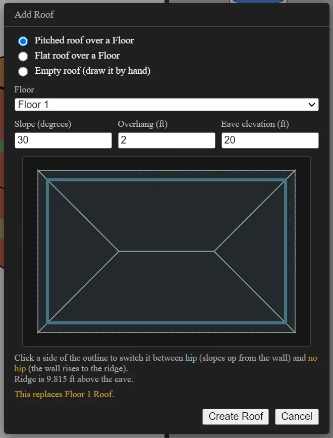
- Pitched roof over a Floor — Slope (degrees), Overhang, and Eave elevation (the roof’s lowest edge, at the tip of the overhang), with a plan of the floor’s outline. Click a side of the plan to switch it between hip (the roof slopes up from that wall) and no hip (a gable: the wall rises to the ridge). The dialog reports the ridge height above the eave.
- Flat roof over a Floor — the roof that generating walls makes (§6.1).
- Empty roof (draw it by hand) — an empty roof collection to draw in.
When the floor already has a roof, the dialog says the new one replaces it. If the floor already has walls, they are regrown up to the new roof in the same undo step. A pitched roof follows the outline of the whole floor, including L, T, and U shapes.
In Automatic mode a pitched roof made here is the Floor’s own automatic roof: its settings become the Floor’s Roof Settings, and the walls always rise to meet it, so the question below is not asked. In Manual mode, when the floor’s Ceiling Height is set (Specify Ceiling Height) below the top of the new roof, Create Roof first asks whether to extend the walls to the roof. Extend the walls sets the floor to Floor or Roof Above with the new roof chosen, so every wall rises to the roof: a gable end to the ridge, the other sides to the roof at the wall line. Keep the set height leaves the walls at the ceiling height, and EP3 fills the gap between them and the roof. The Roof Settings dialog does not ask: when Apply makes a pitched roof whose top is above a set ceiling height, the floor is set to Floor or Roof Above with that roof chosen, and the eave stays where it is.
6.3 Worked example: slope and overhang to ridge height
For a fully hipped roof over a rectangle, the ridge stands above the eave by the horizontal run from eave to ridge times the tangent of the slope. The run is half the outline’s shorter side, measured to the tip of the overhang:
rise = run × tan(slope)
For the 50 ft × 30 ft floor above, with a 2 ft overhang, the outline at the eave is 54 ft × 34 ft, so the run is 34 ft ÷ 2 = 17 ft. At a 30° slope:
rise = 17 ft × tan(30°) = 17 × 0.5774 = 9.815 ft
which is the ridge height the dialog reports. Checked in SI: run = 17 ft × 0.3048 = 5.182 m; rise = 5.182 m × 0.5774 = 2.992 m = 9.815 ft.
The walls under a pitched roof grow up to its sloped planes, so at the wall line the wall top is eave + overhang × tan(slope) = 20 + 2 × 0.5774 = 21.15 ft.
Regenerate…, beside Roof Settings… in a floor’s or roof’s dialog, appears for a pitched roof. It opens the pitched-roof dialog with the roof’s slope, overhang, eave elevation and gable ends. For a roof made before EP3 kept these settings, they are read from the roof’s shape; a value that cannot be read shows its default, and the dialog says which. Regenerate rebuilds the roof over the floor as it is now, for example after moving the floor’s edges, and regrows the floor’s walls to it, as one undo step. Constructions painted on the roof’s faces stay where they were, and skylights keep their position in plan. Dormers and a hand-reshaped roof can’t be kept: when the roof has either, EP3 asks before regenerating. In Automatic mode the regenerated roof is automatic again, and the walls under it, on other floors too, follow it. In Manual mode the roof stays a hand-editable (custom) roof built from the settings, and only its own floor’s walls are regrown.
6.4 Dormers and hand-edited roofs
To add a gable dormer, enter a roof, select a horizontal edge drawn on one of its sloped planes, right-click it, and choose Make Dormer; the dormer has the main roof’s slope. The dormer must fit within one roof plane, or the status bar explains why it was not made.
A roof is ordinary geometry, so you can reshape it, split its faces, or draw one by hand in an empty roof. Each roof face is matched to the Space directly below it. After reshaping a roof, run Refresh Surface Matching (§5) and check the spaces below with Validate (§10.6).
7. Windows and doors
7.1 Add Windows By Exposure
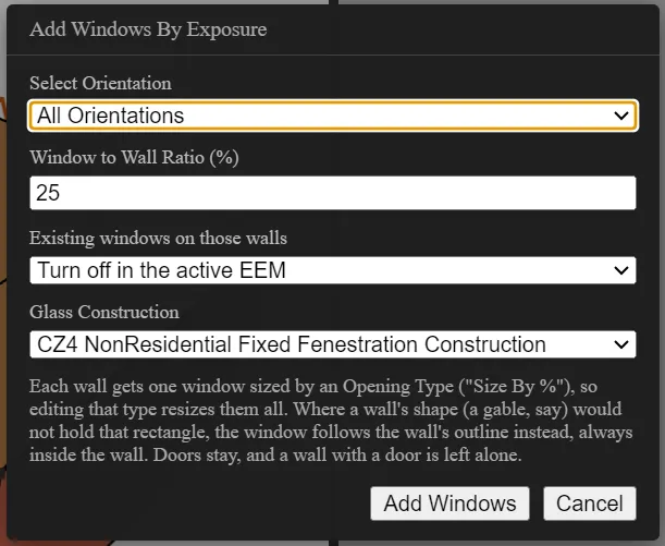
Add Windows By Exposure, in the outliner’s toolbar, adds windows to every exterior wall facing a direction:
- Select Orientation — All Orientations, North, East, South, or West, measured from the building’s North Axis (§2), so South is the building’s south however it is rotated.
- Window to Wall Ratio (%)
- Existing windows on those walls — Turn off in the active EEM or Erase.
- Glass Construction — any glazing construction in the model.
Each wall gets one window sized by an OpeningType set to the ratio (“Size By %”), so editing that OpeningType resizes every window that uses it. On a wall whose top is not level (a gable end, or a wall under a sloped roof), the area is still the ratio of the whole wall, gable included, but the window stays in the rectangular part between the wall’s base and the lowest point of its top. If that rectangle is too short, the window gets wider to keep its area, up to the wall’s width, and past that it fills the rectangle and has less than the ratio. The window is never cut to a custom shape and keeps its OpeningType, and it is refitted each time the walls are regenerated. Glass doors (Windows, Shading, and Daylighting) on a wall are kept and count toward its ratio: a window beside them makes up the rest, and a wall whose glass doors alone meet the ratio gets no window (the status line gives the number of such walls). A wall with an opaque door is left alone. In an EEM other than Global, the new windows are on in that EEM only.
7.2 Drawing windows
The Window Rectangle tool (W) places a window on a wall or roof: enter the wall group or roof, then click two diagonally opposite corners on the face. Select a window to move or resize it; its size can also be typed, and can differ by EEM (Windows, Shading, and Daylighting). Dragging a corner out of line reshapes the window into a custom shape, which applies in every EEM; outside Global the status bar says so. A window or door becomes a door when it is given an opaque construction (§7.3). A glazed window that is door-sized and reaches the bottom of its wall is a glass door: its Surface Type is set automatically and can be changed (Windows, Shading, and Daylighting).
Copy Windows from Floor, in an exterior wall group’s dialog, copies every window from another floor’s exterior walls onto this wall group, shifted by the difference in elevation. If the wall group already has windows, it asks what to do with them: Erase Them, Turn Them Off, or Maintain Them.
Each copy takes its source window’s on and off settings in every EEM, and is checked in every EEM. If a copy would run past the edge of a wall face or overlap another window, the dialog lists the conflicts, naming the window, the EEM, and the size, and offers Divide Windows, Don’t Copy Conflicting Windows, or Cancel. Divide Windows cuts a copy that runs past a face edge into one window per face; the pieces keep the window’s construction and shading but not its OpeningType or EEM sizes, and pieces too small to keep are dropped. Copies that overlap an existing window, or run off the wall only in another EEM’s size, are not copied with either choice. The status bar reports what was divided and dropped, and the whole copy is one undo step.
In the outliner, each window is listed under its wall group, with a power button that turns it on or off in the active EEM. A window whose OpeningType is off in an EEM is off there too. Windows, Shading, and Daylighting covers OpeningType templates and the full set of window fields.
7.3 Painting constructions
The Paint tool (B) assigns a construction to a face or a window. Choose the construction in the Constructions panel; its swatch appears beside the drawing tools. Click a face to paint it, and hold Alt to pick up the construction of the face under the cursor. Painting with Default clears a face’s paint, so it uses its collection’s construction again (the floor’s, wall group’s, or roof’s Construction field). Once a collection has a construction it always keeps one: choose another instead of none (only an imported collection can start without one). In an EEM other than Global, Inherit beside the field clears that EEM’s own choice so the collection follows the EEM it is built on.
Paint belongs to the active EEM. A face painted in Global keeps that construction in every EEM that does not paint it differently; a face painted in another EEM has that construction in that EEM and the EEMs that build on it. Painting with Default in an EEM removes that EEM’s paint, so the face inherits again; the 3D view does not flash for it. A window’s Construction Name list in the Selected Object dialog paints the window the same way. Constructions and Materials covers constructions.
When the face you click is selected, every selected face and window is painted together, as one undo step.
Glazed faces
Paint a wall or roof face with a see-through construction (a glazing construction, a window data file, or a complex fenestration state) to glaze it, for a greenhouse, a curtain wall, or a glass roof. The face stays a face: grow walls, move edges, and split it as usual, and the glass follows. In the 3D view it is drawn as glass.
When it exports, EP3 writes the face’s surface with its collection’s construction (the frame) and adds the glazing as windows on it, 25 mm (1 in) in from the face’s edges and from any window or door on the face. Where the face is narrower than 50 mm (2 in), it stays opaque, so the glazing can come out in several parts: a door at the foot of a glass wall leaves one U-shaped part, and a window in the middle of one cuts the glass in two through it. Glazing with more than four corners is split into rectangles and triangles like any window (Windows, Shading, and Daylighting), and parts too small to model (under 0.1 m across or 0.05 m²) stay opaque.
- The face’s collection needs a Construction: it is what the surface is written with. EP3 refuses glazing paint on a face whose collection has none, and on floor faces, and says why in the status bar.
- Paint belongs to the active EEM, so a face glazed in one EEM has glass only there and the EEMs built on it.
- Select the face to see its surface (with the collection’s construction) and, under Windows & Doors, the glazing EnergyPlus gets. The glazing can’t be edited there, and objects that name a window (a shading control, a daylighting device) can’t pick it; repaint the face to change it.
- The glazing is named after its surface, “<surface> EP3-GLAZING” (“EP3-GLAZING-2” and so on for further parts), so results and the Display Data overlay show it on the face, and importing the file back glazes the face again (Importing EnergyPlus Files). For PRM, the Baseline treats it as the windows it is in the export.
- Model Validation’s Building Geometry tab lists each glazed face with its glass area under Glazed Faces, and flags a face with no glazing left or a collection with no construction (Model Troubleshooting and Quality Assurance).
Making a face into a window
To size or place the glazing yourself, make it a window: select a glazed face and click Make into a window… beside its glazing under Windows & Doors. The Make Window dialog places a window shaped like the face, set in from its edges, with the face’s glazing construction, and the face goes back to its collection’s construction in the active EEM. Nothing changes until you click Make Window; Cancel leaves the face as it was.
- Reveal — Inset from the edges (25 mm, or 1 in, by default) or Glazing ratio, the share of the face’s area the window keeps (80% by default). The dialog shows the window area and, for a ratio, the inset it works out to. A face too small for the reveal is named and left as it is.
- Where the window is on — made in Global, the window is on in every EEM. Made in another EEM, it is off in Global and on in that EEM and the EEMs built on it; change that later as for any window (Energy Efficiency Measures (EEMs)).
- Windows already on the face — each is listed, to Turn off or Delete. The default is Delete in Global and Turn off (in this EEM) elsewhere; deleting outside Global removes the window from every EEM, and the dialog warns you.
The conversion is one undo step. Once made, the window is an ordinary window: move and resize it like any other, and delete it to get the plain wall back. Unlike a glazed face’s glazing, it does not follow the face when the face is reshaped. Painting it with an opaque construction makes it a door.
A face with more than four corners, such as a gable end, gives a window of the same shape. EnergyPlus takes windows of three or four corners, so EP3 splits it into rectangles and triangles when it exports, named after the window (“Window”, “Window EP3-PART-2”, …); results show the window as one (Windows, Shading, and Daylighting).
8. Building shading and site shading
Add Building Shading and Add Site Shading each create an empty shading collection and enter it. Inside a shading collection you draw in three dimensions, since shading (overhangs, fins, neighboring buildings) is three-dimensional: draw faces with Line and Rectangle and give them depth with Push/Pull.
Every face in a Building Shading collection becomes Shading:Building:Detailed, and every face in a Site Shading collection becomes Shading:Site:Detailed. Building shading rotates with the building when North Axis changes, so it suits elements attached to the building, such as fins, balconies, and canopies. Site shading stays put, so it suits neighboring buildings, large trees, and terrain that affect the site’s sun.
Buildings near the site can be looked up on a map and added as Site Shading, one object per building (Buildings and Surroundings from Maps).
Keep site shading to what affects the building: every face is a separate shading surface, and more surfaces lengthen the simulation.
8.1 Transmittance and reflectance
A shading collection can say how much light its faces let through and how much they reflect. Select the collection (in the outliner) or one of its faces to see two fields:
- Transmittance schedule is a schedule of the share of sunlight that passes through, from 0 (opaque) to 1 (clear). A tree, a screen, or a louvre that is deciduous or adjustable takes a schedule; a solid canopy takes none. With no schedule a face is opaque.
- Reflectance is a
ShadingProperty:Reflectanceobject holding the diffuse solar and visible reflectance of the surface, the fraction that is glazed, and the construction of the glazing. It is a reusable object, like a construction: many collections and faces can use one.
A face shows the value it is written with and where it comes from: “from group ‘Tree’” greyed when it follows its collection, or “(face override)” when it has its own. Choose an object in the list to override the group for that face, None to make the face opaque or without reflectance in a group that has a value, and Inherit to clear the override. New… creates a schedule or a reflectance object and opens it. The arrow beside a field opens the object. A collection’s value applies to every face that does not override it, and both can differ by EEM; setting one while an EEM is active changes it in that EEM only. A face of a roof’s overhang takes no properties and stays opaque.
EP3 writes each face’s transmittance schedule on the face, and a copy of its reflectance object named after the face (“<face> Reflectance”). A schedule or reflectance object that is not in the exported EEM is left out, and the export says so. A reflectance object cannot be deleted while a collection or face uses it; the message names what does. The fraction that is glazed needs a glazing construction: when you enter a value above 0 in a reflectance object that has none, a window asks you to choose one and lists glazing constructions only. Cancel leaves the fraction as it was.
An imported file’s transmittance schedules and reflectance objects are put on the collections they belong to, with a face that differs from its group kept as an override (Importing EnergyPlus Files). Model Validation checks them (Model Troubleshooting and Quality Assurance).
9. Background drawings
Floor plans and elevations can be brought in as reference drawings to trace over. A drawing never becomes geometry, and it is not exported; it is saved in the .ep3 file.
9.1 Floor plans
A CAD floor plan can also make a Floor and its Spaces, and CAD elevations can place the windows (Floors and Windows from CAD Drawings).
Click + on the Floor Plans row, choose the floor to link the plan to, and choose the file: an image (PNG, JPEG, BMP, GIF, WebP, TIFF), a PDF (a multi-page PDF asks which page), or a CAD drawing (DXF, or DWG through the free ODA File Converter, which EP3 offers to set up the first time). A plan linked to a floor moves with the floor’s elevation, hides with the floor, and is deleted with it.
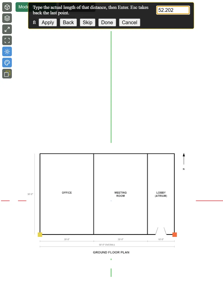
After the import, the Position Background tool walks through its steps. A bar at the top of the 3D view gives each step’s instructions:
- Rotate: click the drawing to turn it 90° at a time until it is the right way up.
- Scale from length: click the two ends of a distance you know on the drawing, type its real length, and click Apply.
- Position: click a point on the drawing, then the matching point on the building.
- Scale to model: click a second point on the drawing, then the matching point on the building. For an image, the drawing scales around pin 1 (the point from Position, or the drawing’s lower-left corner if you skipped Position), and pin 2 lands exactly on the point you clicked. This step is left out when you scaled from a length, since the drawing is then to scale.
- Pins: images only. Four pins straighten a photo or a scan onto its wall or floor (Buildings and Surroundings from Maps). Skip it when the picture is not skewed.
A DXF or DWG drawing comes in at the size its units give, so it has no scale steps. CAD drawings and PDF pages drawn as lines have no Pins step.
Tab, Enter or Skip skips a step, Shift+Tab or Back goes back to the previous one, and Esc takes back the last click. Done keeps the changes, and Cancel undoes the whole session. On a CAD drawing, points snap to the drawing’s line ends and midpoints. To change a drawing later, click ⌖ on its row in the outliner to run Position Background again. Click the row itself to type its position and size and, for a CAD drawing, to turn its layers on or off.
With the drawing in place, trace over it with Line and Rectangle (§4): closing loops on the drawing’s room outlines gives exactly the spaces you want.
9.2 Elevations
Click + on the Elevations row, choose the direction the drawing faces (North, South, East, West, or an angle from north) and whether to mirror it, then choose the file. The drawing stands at that face of the building, as wide as the building, and the Position Background tool starts, working in the drawing’s vertical plane; points on the building snap to its vertices. Elevations are grouped in the outliner by direction, and each direction’s eye button shows or hides its drawings.
9.3 Elevation Wrap
The Elevation Wrap row, at the top of the Elevations section, switches the wrap on and off. While it is on, each visible elevation drawing is projected onto the exterior walls and roofs it faces, as a semi-transparent overlay, so the drawing’s windows and doors sit on the walls where they will be drawn. The wrap follows changes to the geometry and drawings as you work. It changes only the view, and only visible drawings are wrapped; it needs walls and roofs to wrap onto.
10. A worked example: a two-story building with an atrium
This example starts from the same Model Wizard selections as the worked example in The Model Wizard (Office Building - General internal loads, ASHRAE90_1 2022 CZ4 NonResidential constructions, the PSZ-AC system, and a Climate Zone 4A weather file), but on the Building Geometry tab choose I want to draw my own building geometry. Everything after that uses the tools in this chapter.
10.1 The building
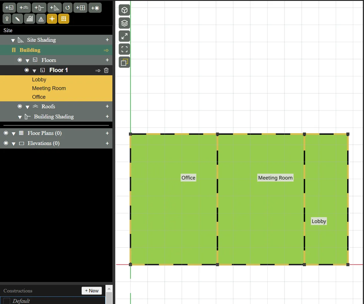
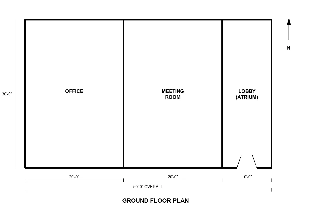
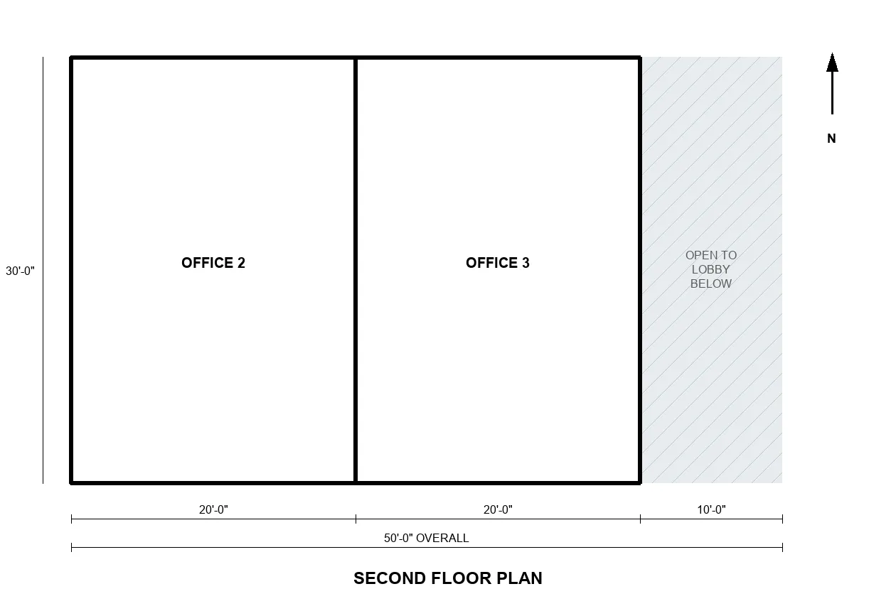
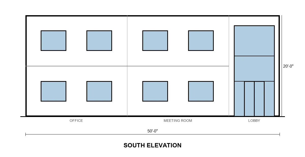
A 50 ft (east-west) × 30 ft (north-south) footprint, two stories with 10 ft floor-to-floor heights: a 20 ft Office wing at the west end, a 20 ft Meeting Room wing in the middle, and a 10 ft Lobby at the east end. The second floor covers the two wings, as Office 2 and Office 3, and leaves the Lobby open as a double-height atrium up to the 20 ft roof.
10.2 The ground floor
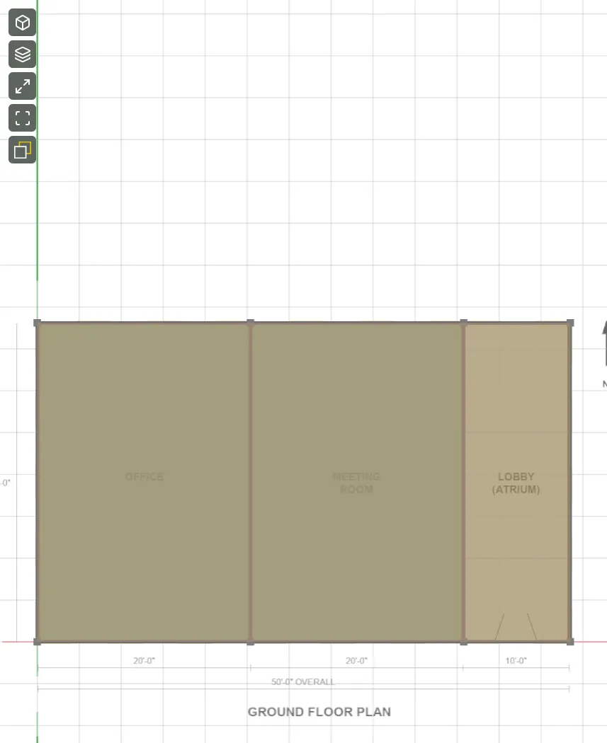
- Click Add Floor, leave Choose method: at Create from Scratch, enter a Ceiling height of 20 ft, leave Starts at at 0, and click Create. Floor 1 is created and entered.
- Optionally, import the ground floor plan as a background (§9.1): link it to Floor 1, skip the Rotate step, scale it by clicking the ends of the 50 ft overall dimension and typing 50, and position it by clicking the drawing’s southwest corner and then the origin.
- In top view, choose Rectangle, click the origin, point up and to the right, type
50,30, and press Enter. - Choose Line. Click the southwest corner, point east, type
20, and press Enter: this places a point on the south edge 20 ft from the corner. Start a new line at that point, point north, type30, and press Enter to split the rectangle. Repeat from the new point for the second division at 40 ft. Three spaces appear. - Rename the spaces Office, Meeting Room, and Lobby in the outliner.
- In Floor 1’s dialog, check that Floor Height Calculation Method is Specify Ceiling Height and Ceiling Height is 20 ft, so the Lobby’s walls run the full two stories.
10.3 The second floor and the atrium
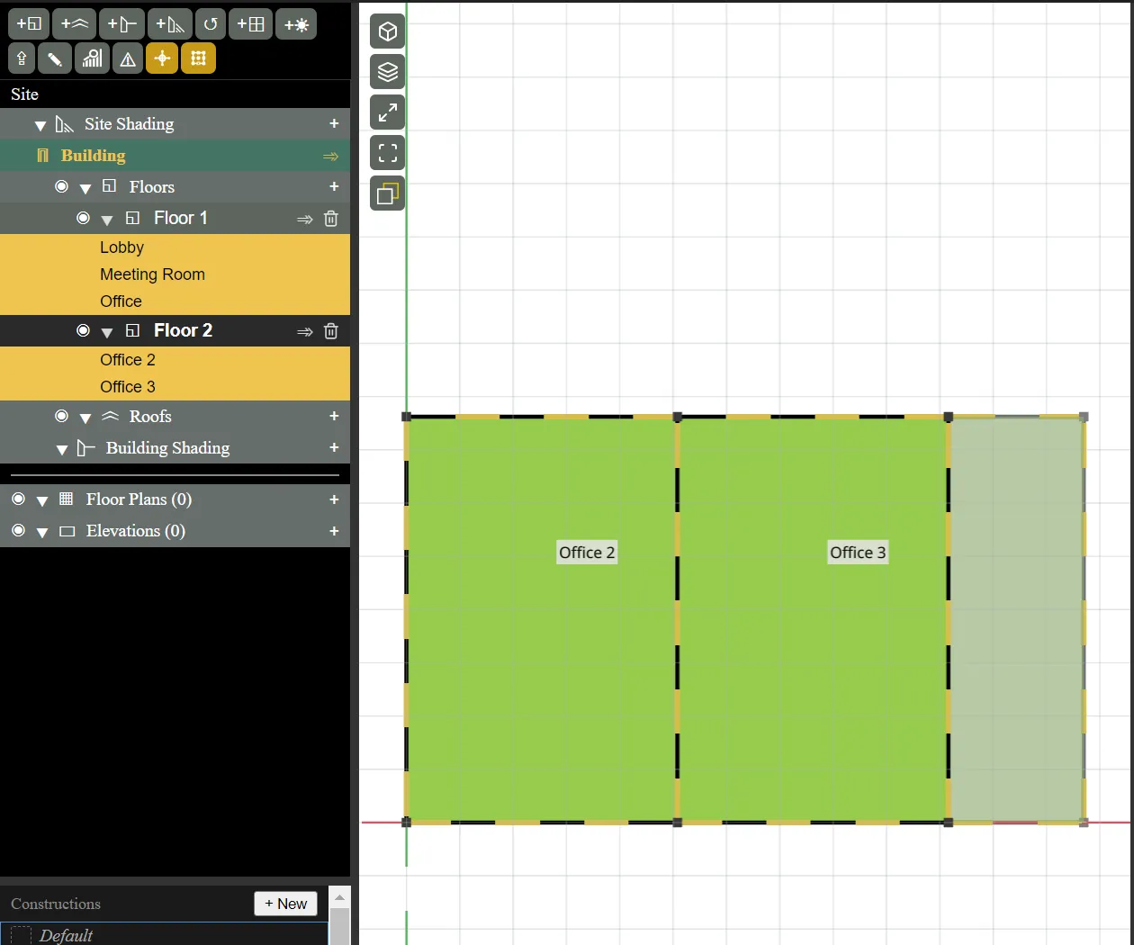
- Click Add Floor, choose Copy Existing Floor, choose Floor 1 under Floor to copy, and set Starts at to 10 ft. Floor 2 starts with copies of all three spaces.
- On Floor 2, use Erase to drag across the Lobby’s three outer edges (south, east, and north). The Lobby’s area on Floor 2 is removed, leaving Office and Meeting Room; rename them Office 2 and Office 3.
- In Floor 2’s dialog, set Ceiling Height to 10 ft, so its walls stop at the 20 ft roofline.
10.4 Walls and roofs
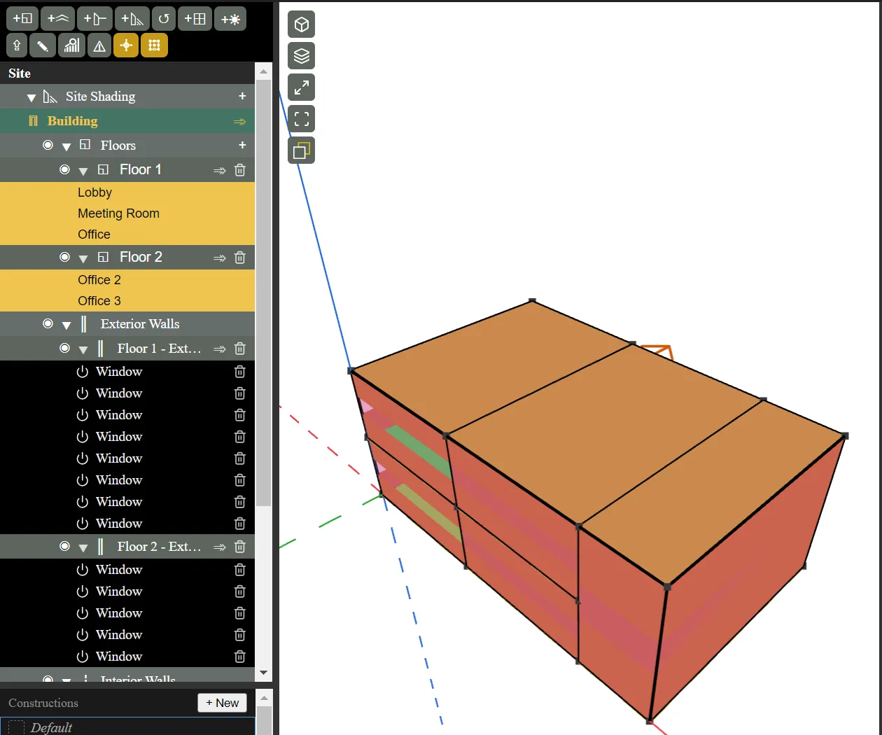
In Automatic mode the walls and roofs below are already in place as you finish each floor. In Manual mode, click the outliner’s wall-generation button, and EP3 grows the walls for both floors:
- Floor 1’s walls rise to 20 ft, but along the wings they are cut at 10 ft by Floor 2’s slab, so each wing is two stories of ordinary walls.
- The Lobby’s walls have nothing above them, so they run the full 20 ft in one piece: a two-story atrium, from one field setting and an area not drawn on the second floor.
- The wall between Office 3 and the upper part of the Lobby becomes an interior wall between those two spaces.
- Each floor with nothing above it gets a flat roof at 20 ft: Floor 1’s roof over the Lobby and Floor 2’s roof over the two wings, together one continuous roofline.
The Lobby is at the end of the building, so Floor 2’s outline is one rectangle and gets its roof automatically. An atrium in the middle of the building would split Floor 2 into two separate regions, which get no automatic roof (§6.1).
10.5 Windows
Use Add Windows By Exposure (§7.1) with All Orientations and a 25% window-to-wall ratio to give every exterior wall a window. For the Lobby’s storefront, enter Floor 1’s exterior wall group and draw its glazing with the Window Rectangle tool, following the south elevation; the entry doors are drawn the same way, from the foot of the wall, which makes them glass doors (Windows, Shading, and Daylighting). With elevation drawings imported and Elevation Wrap on (§9.3), the drawing’s windows show on the walls to draw over.
10.6 Checking the result
Run Validate from the top toolbar before simulating. Its Space Enclosure and Unexpected Construction Types checks find spaces that are not closed and surfaces whose construction does not suit their boundary; Model Troubleshooting and Quality Assurance covers them. A surface’s Outside Boundary Condition, which EP3 sets from the geometry, can be overridden in the surface’s dialog when the geometry cannot express the intended boundary.
To see each flagged surface in the 3D view, turn on the unexpected adjacency highlighter in the outliner (§11).
From here, assign the PSZ-AC units to the zones, simulate, and review the results as in the Model Wizard’s worked example. Running Simulations and Viewing and Interpreting Results cover both.
11. Diagnosing geometry problems: unexpected adjacency
The ⚠ button in the Building Geometry Outliner’s toolbar highlights the surfaces whose boundary or construction does not match their geometry. Turn it on and the problem faces are hatched in the 3D view, and a badge on the button counts them. The highlight is live: it clears as soon as you fix a surface. Hover over a hatched face to see why it is flagged.
The colours, in order of precedence when a face has more than one problem:
- Blue: you set the outside boundary condition by hand, and it differs from the one the construction expects. A hand-set boundary that matches the construction is not marked.
- Red: the face has no construction. Paint it (§7.3).
- Orange: the outside boundary does not match the construction. For example, an exterior-wall construction on a wall that borders another Space. Orange also marks a face that touches more than two Spaces, and a face that lies exactly on top of another, such as a Floor 2 slab sitting on the Floor 1 roof.
- Green: a wall, roof, or floor that is not matched to any Space. EP3 treats it as shading, outside the building’s thermal envelope. Overhangs and fins often show green, and that is correct.
A window or door takes the colour of the surface it sits in when it has no construction, or when its construction expects a different boundary from that surface. The badge counts each window with its surface, so a surface and its windows count once.
Resolve red faces before you move on. A face without a construction hides any other problem it has until it is painted. Then work through orange, and check the blue faces: each one is a boundary you set by hand, so confirm it is still right.
The hover menu on the button or badge has four options:
- Hide / Show surface tooltips turns the hover reasons on or off.
- Refresh matching for all unexpected surfaces matches every flagged and shaded face to its Spaces again. It is one undo step. Use it after drawing walls or roofs by hand, as with Refresh Surface Matching.
- Set all outside boundary condition to automatic clears every hand-set boundary in the model. It appears only when there are some.
- One row per collection, showing its name and the number of flagged faces. Click the name to enter that collection with its still-flagged faces selected. The camera stays where it is. The ↺ button on the row re-matches just that collection’s flagged faces.
The highlighter and View Building Data cannot be on at the same time. Turning the highlighter on puts the active tool back to Select. Whether it is on is not saved with the model.
Once the badge shows ✓, run Validate (§10.6).
This handbook is also built into EP3 (Help), where its EnergyPlus links open the EnergyPlus Reference. Technical specifications · Book a demo