Buildings and Surroundings from Maps
1. Overview
EP3 can make a Building from a map, with its outline, its height, and the buildings around it. A photo or a scanned elevation can then place its windows. This chapter covers four tools:
- Building from Map makes the Building, its Floors, and its Spaces from one or more buildings picked on a map (§3). Add more buildings adds further buildings to a Building that already has geometry (§4).
- Neighbouring Buildings adds the buildings around the site as Site Shading and makes the walls that touch them adiabatic (§5).
- Photo pins straighten a photo or a scanned drawing onto the wall it shows (§6).
- Windows from image colours finds the windows and doors in a photo or an image elevation from the colours you pick (§7).
The map tools need map lookups (§2). A building outline from a file (GeoJSON or KML) needs neither map lookups nor an internet connection, and photo pins and image colours work with any image.
2. Map lookups
Map lookups are off until you turn them on. A map sends requests from your computer to the map services, so the first time a map tool needs them it shows a privacy note: Turn on allows them, and Cancel leaves them off. An outline file can still be used with lookups off. The setting is Allow map lookups in File > Settings… > Map Lookups; turning it off there stops every lookup at once.
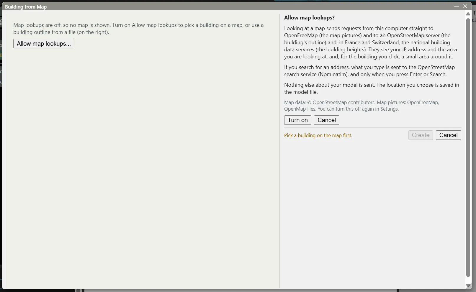
What is sent, and where:
| What | Where it goes | When |
|---|---|---|
| The map pictures | OpenFreeMap | While a map is shown |
| A building’s outline, height, and parts | An OpenStreetMap server | Once for each selection, and when you click a place where the map draws no building; panning and zooming send nothing |
| Building heights in France and Switzerland | The national building data services (IGN BD TOPO, the Swiss federal building register) | When the map is in those countries and a height is needed |
| An address you type | The OpenStreetMap search service (Nominatim) | Only when you press Enter or click Search |
These services see your IP address and the area you are looking at. Nothing else about your model is sent, and the requests go straight from your computer to the services, never through EP3’s server.
The location you choose is saved in the model file as the site location (latitude, longitude, and the map’s zoom), with the OpenStreetMap ids of the buildings used. Every map tool then opens at that place and zoom. A model with no site location opens at its Site:Location object’s position if it has one, else at the weather file’s station, else at the last place you looked.
The data licences require the credits shown under the map: “Map data: © OpenStreetMap contributors”, the map pictures’ credit, and, when a national service answered, “Building heights: IGN BD TOPO (Licence Ouverte)” or “Building register: © OFS/BFS, geo.admin.ch”.
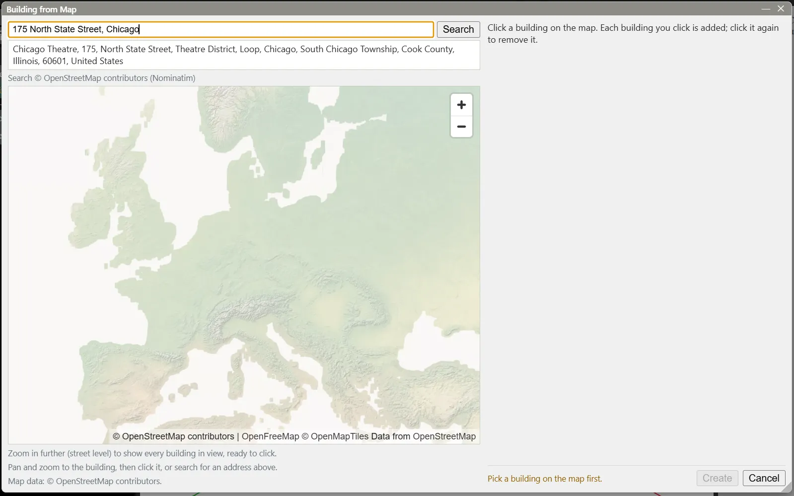
The search box above the map takes a street address or a place name. Choosing a result moves the map there.
3. Building from Map
3.1 Starting
When the model has no Building, click + on the Building row of the Building Geometry Outliner. The question Make the Building from: offers:
- From the map — click one or more buildings on an OpenStreetMap map. Their outlines, levels, and heights come with them.
- From an outline file (GeoJSON/KML) — a footprint drawn in Google Earth, exported from a GIS, or downloaded from a city’s open data. The file chooser opens at once, and a file with several buildings lists them to choose from.
The Building from Map dialog is modal: the rest of EP3 is unavailable while it is open. Cancel or Esc changes nothing, and Create is one undo step.
3.2 Picking buildings
Pan and zoom to the site, or search for an address. Zoom in until the buildings show as shapes; when the map is too far out, a message asks you to zoom in.
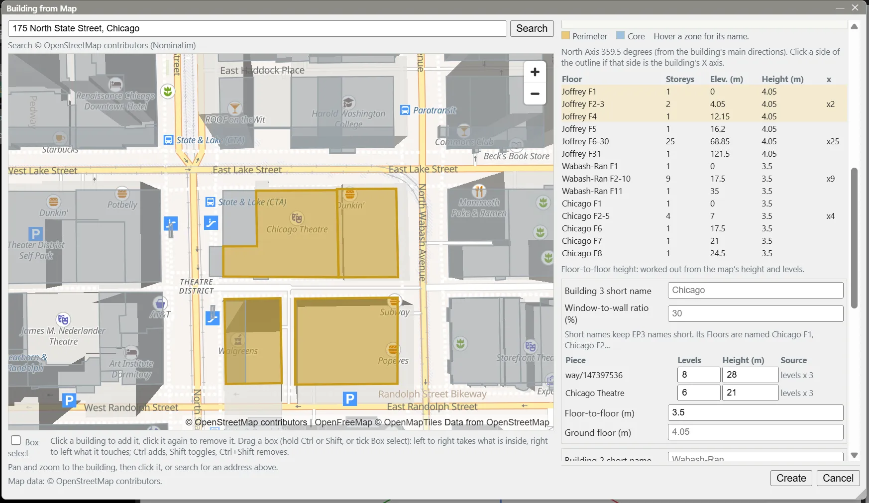
- Click a building to add it, and click it again to remove it. The buildings that will be made are amber; the others are grey.
- Box select adds many at once: drag a box while holding Ctrl or Shift, or tick Box select and drag. Left to right takes the buildings wholly inside the box; right to left takes every building the box touches. As elsewhere in EP3, Ctrl adds, Shift toggles, and Ctrl+Shift removes.
- A building cut by the edge of a map tile is joined from its pieces. A building the map draws as several pieces is picked piece by piece.
Once the selection settles, EP3 asks OpenStreetMap once for the exact outlines, levels, heights, and building parts of the selected buildings. A progress bar names each step as it runs, for example “Step 2 of 4: Looking up the exact building outlines (OpenStreetMap)”, with the time taken and a Cancel button. Where a step has a count, the line shows it, as in “Looking up building heights from national data 3 of 7”. The map stays usable, and Create waits until the work is done. If the OpenStreetMap servers are busy or do not answer, the line “OpenStreetMap servers are busy; using the map’s outlines.” appears and the Building is made from the map’s outlines. These are accurate to about 0.5 m, and their height is the one the map draws.
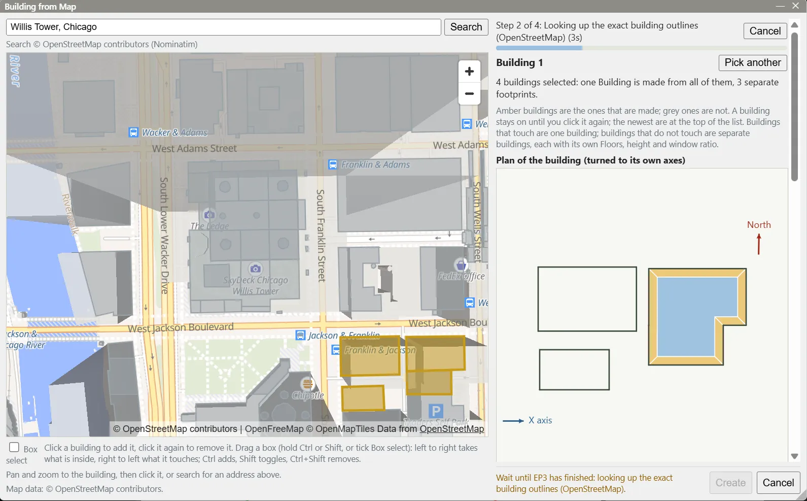
A click where the map draws no building asks OpenStreetMap for the building at that point, or the nearest one within 10 m; when there is none, the dialog says “No building is mapped there”. A building from an outline file or from the map’s outlines has no building parts.
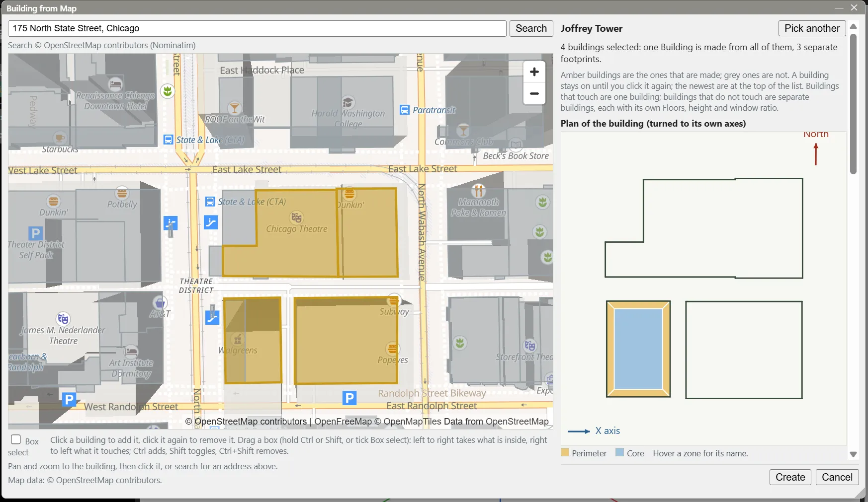
The pane on the right sums up the selection (“3 buildings selected: one Building is made from all of them, 2 separate footprints.”) and shows a plan of what will be made, turned to the building’s axes, with the zones filled by kind (Perimeter, Core, Whole Floor). Hover a zone for its name.
3.3 Levels, heights, and one row per piece
Each separate building has a table with one row for every piece selected in it: the piece’s name, Levels, Height, and the source of the height. Below the table are Floor-to-floor and Ground floor. Hovering a row, a piece on the map, or a piece in the plan highlights it in all three. Every field can be edited, and the units follow the model’s unit system.
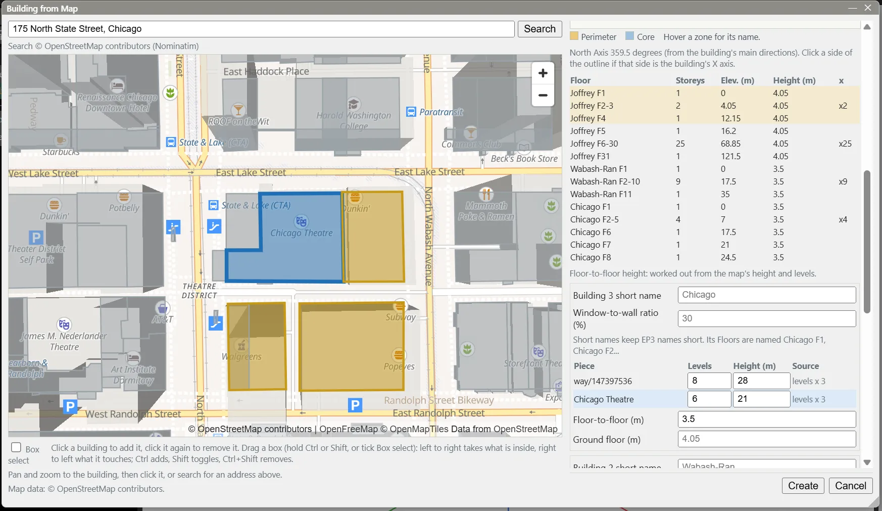
A height comes from one of these sources:
- “OSM height” — the height mapped in OpenStreetMap;
- “national data” — IGN BD TOPO or the Swiss building register, used when OpenStreetMap has none;
- “levels x 3.5 m” — a mapped number of levels at the Floor-to-floor height, which the label names (“ground floor + levels x 3.7 m” once a Ground floor height is set);
- “map tiles” — the height the map draws;
- “default” — nothing is known, so one 3.5 m storey is assumed, and an amber note says so;
- “set by you” — a value you typed. For a building of one piece the label still names the method, for example “ground floor + levels x 3.7 m (set by you)”, because the Height stays the sum of the storeys.
For a building of one piece, Levels, Height, Floor-to-floor, and Ground floor are linked, so the Height is always what the storeys add up to and no part storey is made. Levels are whole storeys. Editing Levels, the Floor-to-floor, or the Ground floor keeps the others and changes the Height; editing the Height keeps the Levels and the Ground floor and changes the Floor-to-floor. For example, 7 levels with a 5.9 m ground floor and 3.7 m above make 5.9 m + 6 x 3.7 m = 28.1 m. With a height and no levels, Levels is the height divided by 3.5 m, rounded, and the Floor-to-floor is set so the storeys add up to the height. A Floor-to-floor outside 2.4 to 6 m shows a warning but is accepted. Ground floor is an optional, different height for the lowest storey. A building with parts, such as a podium and a tower, has a row per part and one shared Floor-to-floor; a part’s Height follows the Floor-to-floor and Ground floor until you type one.
3.4 Separate buildings
Selected buildings that touch are made as one building, each piece keeping its storeys. Buildings that do not touch become separate buildings in one Building. Each separate building gets:
- a short name, used in its Floor names. The default is the first word of its OpenStreetMap name, cut to 10 characters, or A, B, C. A longer name shows a warning but is accepted. A name the model’s Floors already use is replaced with a letter;
- Floors that no other building shares, named “A F1”, “A F2-4” (a single unnamed building gets “F1”, “F2”), with that building’s levels, floor-to-floor, and ground floor heights;
- a Window-to-wall ratio (%), if you set one; otherwise the shared ratio.
3.5 Floors, zoning, and North Axis
- Zoning is Core and perimeter or One Space per Floor. Core and perimeter makes a perimeter ring of the Perimeter depth (4 m by default), split by facade direction, around a core. A part of the outline narrower than twice the depth is all perimeter. A courtyard gets a perimeter ring of its own and stays open.
- Perimeter Space Type and Core Space Type list the model’s Space Types and the library’s. Each Space is named from its number, Space Type, and zone, such as “3 Office North Perimeter”. In a model that assigns Space Types by name, the name gives the Space its type; otherwise the type is assigned directly (Spaces and Zones). A library Space Type brings the EEMs of the library that change it, and the result line lists them as “Added EEMs: …”.
- North Axis. EP3 finds the building’s main directions, turns the outline so they lie along X and Y, and sets the Building’s North Axis so the true orientation is kept (Creating Building Geometry). The plan shows the North Axis and how it was found. Click a side of the outline in the plan to make that side the X axis; Find the axes automatically undoes the choice.
- Consecutive storeys with the same outline become one Floor with a Floor multiplier. A building with parts is sliced storey by storey, so a podium and a tower keep their outlines. Roofs are flat.
3.6 Windows and party walls
- Window-to-wall ratio (%) is 30 by default. 0 or blank makes no windows, and 100 or more is held at 99 with a warning. The windows are made on the exterior walls at Create.
- Party walls. A wall against a touching building you did not select is made adiabatic. Where a lower neighbour covers only part of the wall, the wall is split first. Nothing is added as shading. After Create, the status line says how many walls were made adiabatic.
- Adiabatic walls never get windows. Every automatic window tool skips them: the window-to-wall ratio here and in the Model Wizard, Add Windows By Exposure, Windows from Elevations, and Copy Windows from Floor.
3.7 Create
Create makes the Floors, Spaces, walls, windows, and party walls in one undo step and saves the site location. The dialog then goes straight on to the Neighbouring Buildings dialog (§5), with a summary starting “Made the building from the map” at the top; with map lookups off, it closes.
When Create is greyed out, a line beside it gives the reason: nothing is picked, EP3 is still working on the selection (the step is named), the plan is being worked out or was refused, the perimeter depth is not above 0, or the window-to-wall ratio is not a number. An empty perimeter depth takes the default.
4. Adding more buildings later
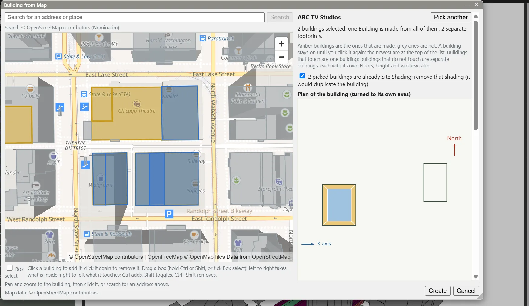
When the Building already has geometry, the Building row of the Outliner shows Add more buildings +. It asks the same question, From the map or From an outline file, and opens the dialog at the saved site and zoom. The model’s Building is outlined in amber and cannot be clicked. Pieces already in the model are blue and cannot be picked again.
- The new buildings become new Floors of the same Building, placed in its coordinates. The North Axis and the site stay as they are, so the axis controls are hidden and a note says so.
- Where a new building touches the existing one, the walls become shared interior walls with the model’s default interior wall construction. Windows on the shared wall are removed from both sides; windows above or beside a lower new building stay. A wall that is still an outside wall against another building is made adiabatic, as in §3.6.
- A picked building that is already Site Shading can be taken over: a checkbox, on by default, removes that shading in the same undo step so the building is not modeled twice.
- A Building drawn by hand, with no saved site location, is refused with “Place the site on the map first”. Place the site pin… opens the pin step of the Neighbouring Buildings dialog (§5.2).
5. Neighbouring buildings as Site Shading
5.1 Selecting and adding
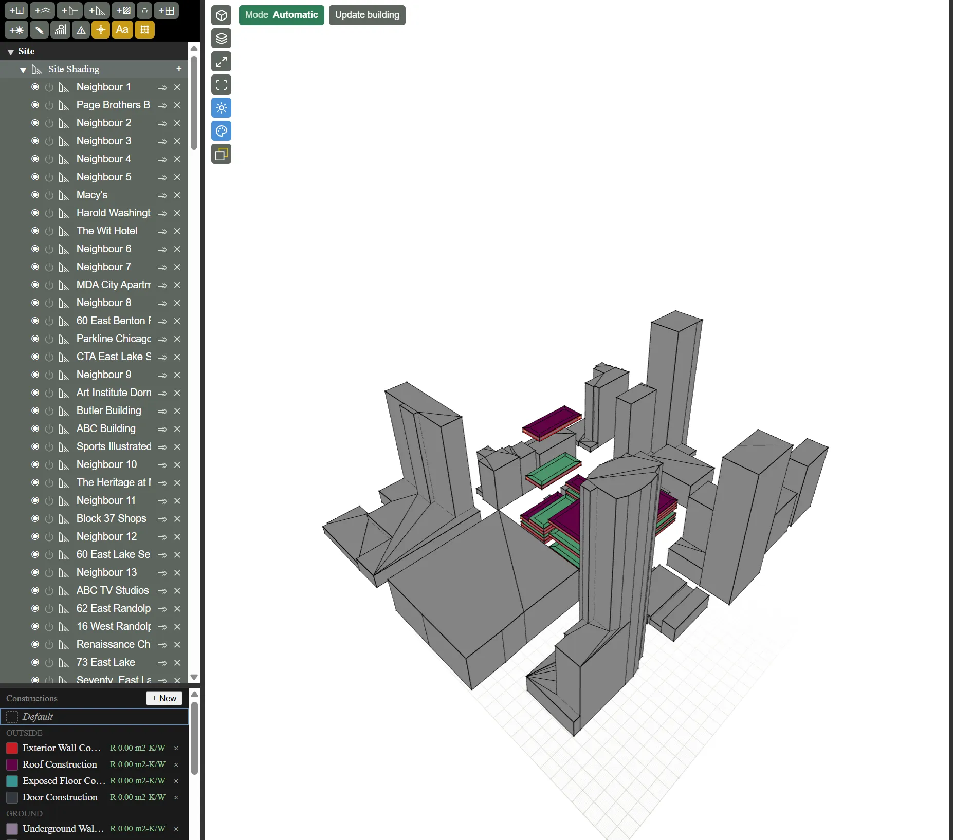
Click + on the Site Shading row. EP3 asks whether to add neighbouring buildings from the map as site shading: Get neighbouring buildings… opens the Neighbouring Buildings dialog, and Add an empty site shading group adds an empty collection. Esc adds nothing. The dialog also opens after Create in Building from Map.
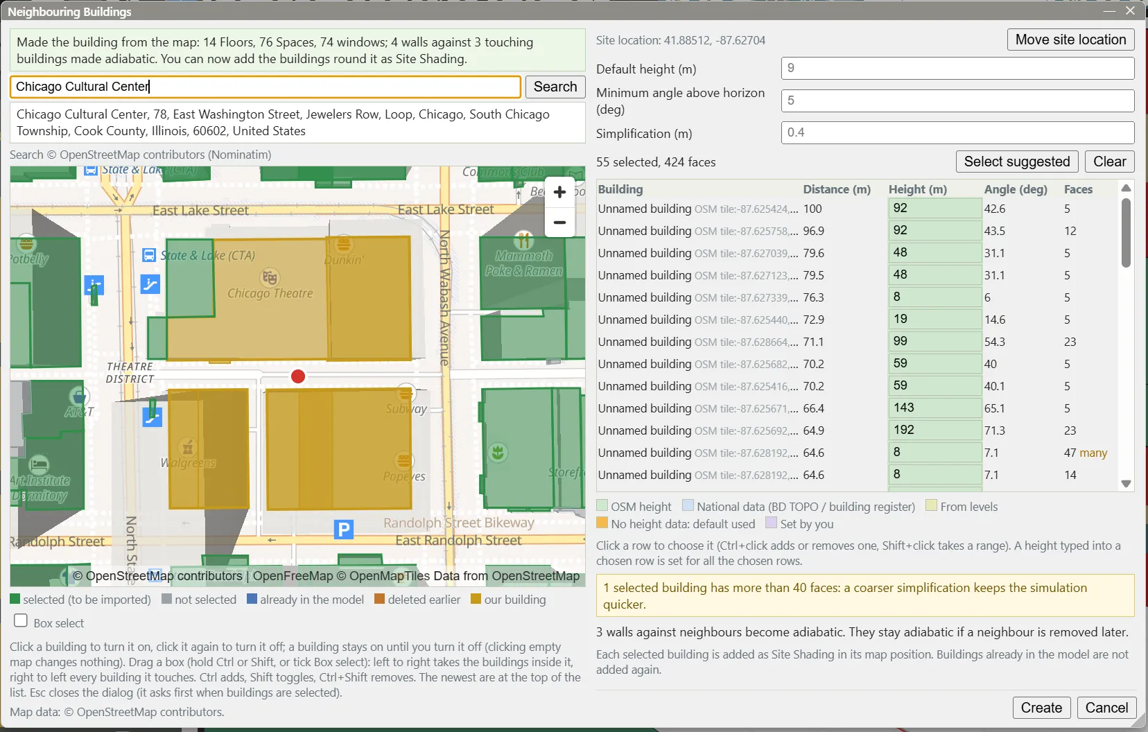
The map shows the buildings in view once it is zoomed in to street level. Your Building is outlined in amber. Buildings already in the model are blue and cannot be selected.
- Click a building to turn it on, and click it again to turn it off. Clicking empty map changes nothing. Box select works as in §3.2.
- Select suggested selects the new buildings within 100 m of yours whose tops are higher than the Minimum angle above horizon (5 degrees by default), seen from your building. It replaces the selection. Nothing is selected until you choose.
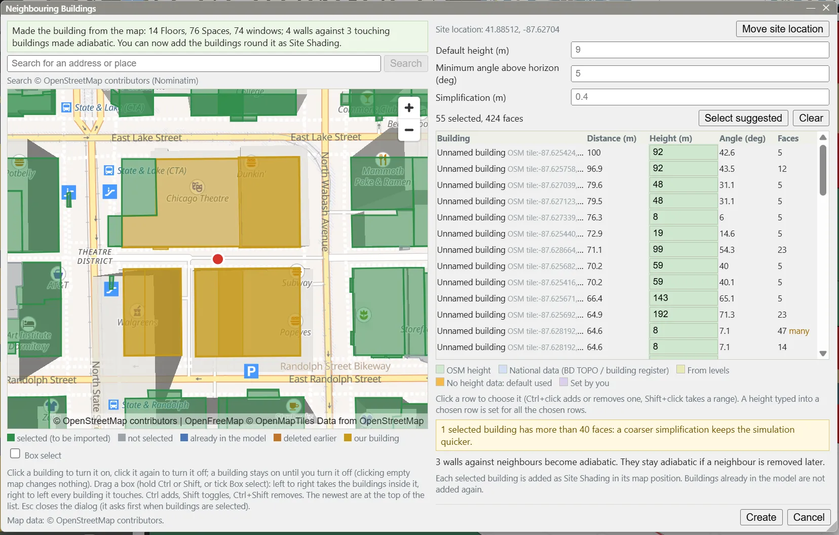
- Clear empties the selection. Esc closes the dialog, and asks first when buildings are selected.
The list shows only the selected buildings, newest first, with their distance, Height, and faces. A neighbour mapped with levels and no height stands 3 m a level, the height OpenStreetMap’s own 3D maps give a level. Each height is coloured by its source: OSM height (green), National data (blue), From levels (yellow-green), No height data: default used (amber, bold), and Set by you (lilac). Type a height in a row to set it. Choose several rows (click a row, Ctrl+click to toggle one, Shift+click for a range, or select buildings on the map), and a height typed into one of them is set for all. Clearing the field removes the typed height. Default height applies to buildings with no height from any source.
Simplification merges sides that are closer to a straight line than the set distance, which gives fewer faces and a faster simulation. A building with over 40 faces, or neighbours with over 500 together, shows a warning.
The line “N walls against neighbours become adiabatic” counts your walls that stand against a selected neighbour. A wall is split first where the neighbour is lower or narrower than it. These walls stay adiabatic if the neighbour is removed later. Create reads the exact OpenStreetMap data for the selected buildings, then adds the neighbours in one undo step. A progress bar names each step, with Cancel while EP3 waits for OpenStreetMap. The status line then gives the counts. When Create is greyed out, a line beside it gives the reason.
Each neighbour is a separate Site Shading object, with a roof and a wall on every outward side, exported as Shading:Site:Detailed. Like any other object, it can be turned on or off per EEM, so a design without a tall neighbour is one EEM away. Site Shading does not turn with the North Axis (Creating Building Geometry). EP3 remembers a neighbour you delete: on a later visit it is shown in orange as “deleted earlier” and left unselected, so it comes back only if you select it.
5.2 The site pin and moving the site
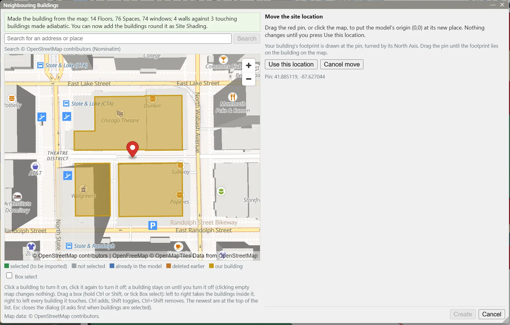
A model with no saved site location first asks Where is the site? The red pin marks the model’s origin (0,0). It starts at the best known place; click the map or drag the pin to move it. Your Building’s outline is drawn in amber at the pin, turned by the North Axis, so you can line it up with the building on the map. Use this location saves the location in one undo step. Nothing is looked up before then.
To change a saved location, click Move site location, beside the “Site location: latitude, longitude” line. Drag the pin or click the map, then click Use this location; Cancel move keeps the saved location. When neighbours are linked to the site, EP3 asks what to do with them:
- Erase them deletes the linked neighbours and saves the new location.
- Keep them saves the new location and keeps the neighbours as ordinary Site Shading at the same model coordinates, so on the map they are displaced by the move.
- Do not move changes nothing.
Walls already made adiabatic against neighbours stay adiabatic either way.
6. Photos and scanned drawings
A photo of a facade, or a scan, is rarely square to its subject. Position Background straightens it onto its wall (an elevation) or its floor (a plan) with up to four pins. Importing an image removes its location and camera data, so the model keeps nothing about where a photo was taken.
Every image ends Position Background (Creating Building Geometry) with the Pins step, as a floor plan or an elevation: a photo, a scan, a screenshot, or a PDF page imported as an image. CAD drawings and PDF pages drawn as lines have no Pins step. The steps run in this order:
- if you scale from a known length: Rotate (when offered), Scale from length, Position (pin 1), Pins. The length sets the scale, so Scale to model is left out;
- if you skip Scale from length: Rotate (when offered), Position (pin 1), Scale to model (pin 2), Pins.
Click Skip (or press Tab) on the Pins step when the picture is not skewed.
Four coloured pins appear on the picture, in place on its wall in the 3D view: pin 1 blue, pin 2 orange, pin 3 green, and pin 4 purple. Pin 1 holds the point you clicked in Position, and pin 2 the point you clicked in Scale to model, which sits exactly on the building point you matched it to. A pin whose step did not run sits on an image corner, chosen to spread the pins well, or on the middle of a side when three corners would put three pins in a line. When you skip Position, pin 1 takes the lower-left corner. Each pin is fixed where its point of the picture lies when the step opens, so nothing moves until you drag one.
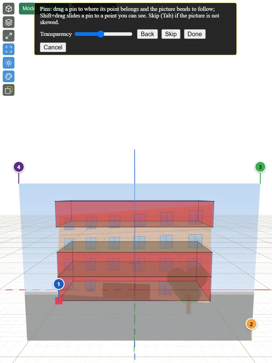
- Drag a pin to where its point belongs. The picture bends to follow, and the other three pins stay where they are. A pin snaps to the origin and to the building’s vertices within a short distance of the pointer on screen: the corners of every Floor, wall, and roof, including the eaves and the parapet, and the nearest one wins. On a corner where Floors stack, zoom in so the vertex you want is the nearest. A vertex another pin already holds is not snapped to, since two pins cannot share a point.
- Shift+drag a pin to slide it along the picture without bending it, so it holds a different point. Use this when a corner is hidden behind a tree or a car: move the pin to a window corner you can see.
- The Transparency slider lets the model show through the picture. It changes only the view and ends with the step.
EP3 refuses a layout that puts three pins on one line, turns the picture over, or folds it. The bar gives the reason, and the pins stay where they were. Done, Skip, Tab or Enter ends Position Background, and Cancel undoes the whole session. Remove pins in the drawing’s fields in the Outliner returns the picture to its plain rectangle, in one undo step.
For a good result:
- spread the pins across the facade, on corners you can see clearly, such as window and wall corners;
- avoid ultra-wide lenses, which curve straight lines;
- pin points on the plane of the wall: balconies, reveals, and anything else that stands out from the wall shift against it as the camera angle changes.
Windows from Elevations reads a pinned photo as a straightened copy, measured in meters (§7).
7. Windows from image colours
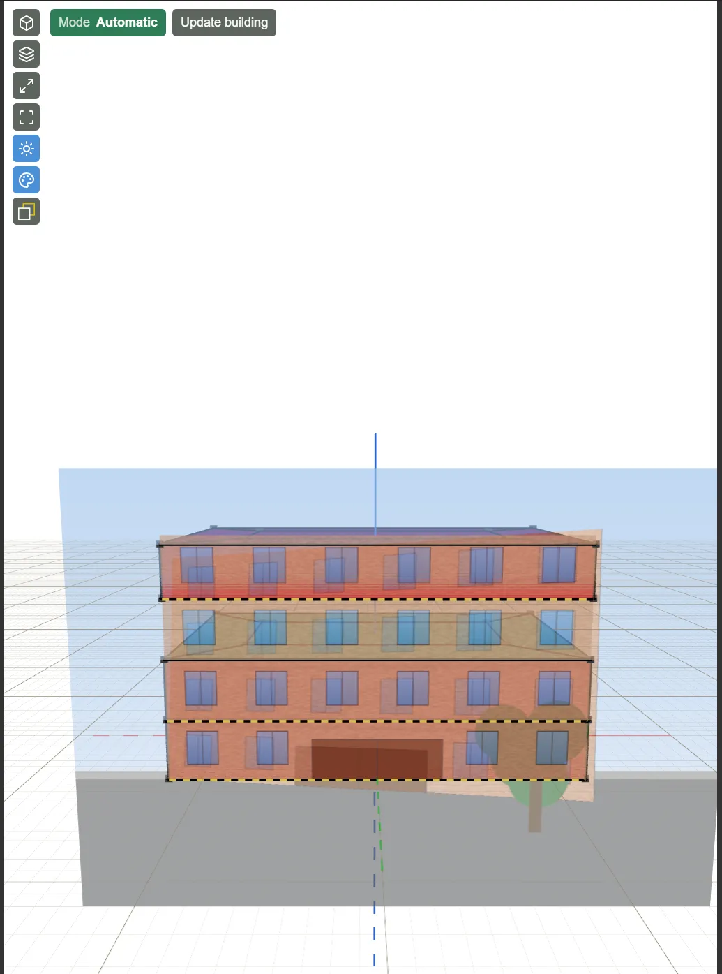
Windows from Elevations (Floors and Windows from CAD Drawings) reads image elevations as well as CAD ones. Import a photo, a rendering, or a scanned elevation with + on the Elevations row and place it with Position Background, using pins for a photo taken at an angle (§6). One run can mix CAD and image elevations.
An image elevation has a Colours step where a CAD elevation has Layers. The steps are Layers (when the run has a CAD elevation), Colours (when it has an image), and Preview.
7.1 The Colours step
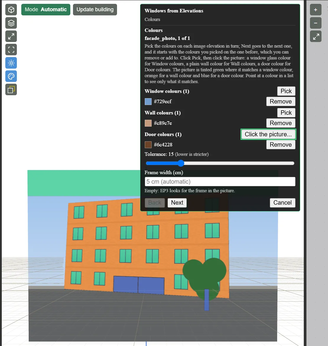
The step shows one image elevation at a time (“East elevation, 2 of 4”), with the view turned to face it. Next goes to the next image elevation, which starts with the colours picked on the one before; remove or add colours as needed. Back goes to the previous one.
Three lists hold the colours: Window colours, Wall colours, and Door colours. Click Pick, then click the picture on the glass of a window, a plain stretch of wall, or an opaque door. While you work, the picture is tinted: windows green, walls orange, and doors blue. Point at a colour in a list to see only what that colour matches. Remove takes a colour out.
- Tolerance is how far a pixel’s colour may be from a picked colour and still match it (2 to 60, default 15). Lower is stricter. Shadows and gradients need a higher value.
- Frame width is the width of the frame around each window. When it is empty, EP3 assumes 5 cm and searches outward, up to 15 cm a side, for where the wall colour returns. A typed value is used as typed, with no search. A window’s size is the rough opening, so a frame the same colour as the wall needs a typed width.
- A window is a coloured region that fills about 70% or more of its bounding rectangle. Panes separated by thin, aligned mullions merge into one window, and edges snap to the facade’s rows and columns. Windows smaller than 0.25 m are left out.
Wall colour only. With a wall colour and no window colour, everything the wall surrounds counts as window, and the note “No window colour: everything enclosed by wall counts as window.” appears. A region that touches the edge of the picture is taken as sky, ground, a neighbouring building, or shade, and is dropped, so the picture must show some wall all around each window. On a pinned photo the tint is approximate: it is drawn from the original picture, while the windows are found on the straightened copy.
Door colours make doors, which are opaque doors (Windows, Shading, and Daylighting). A door takes the Doors default construction, set in Model Settings > Default Constructions, a Space Type, or a Space. If none of them sets one, the door has no construction; choose one before simulating. Doors are left out of every window count and area, and listed separately.
Next is greyed out until the image elevation has a window, wall, or door colour, with the reason: “Pick a window colour, or a wall colour (then everything the wall surrounds counts as window).”
7.2 Preview, OpeningTypes, and walls no drawing shows
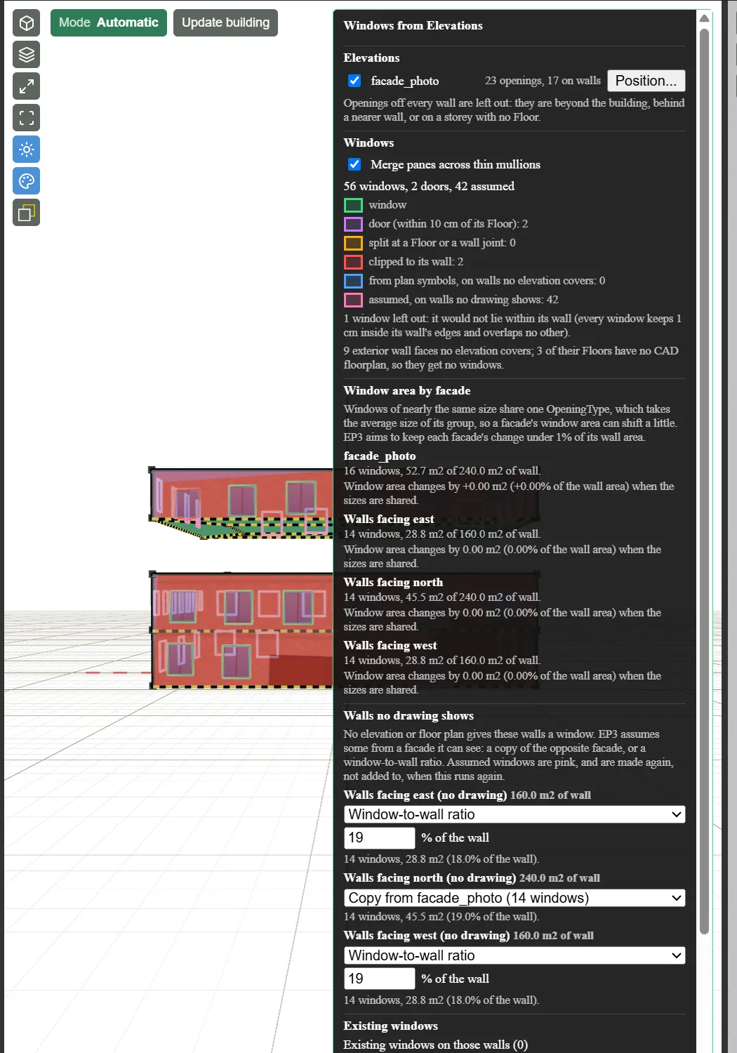
From the Preview on, an image works as a CAD elevation does: the windows are drawn on the walls, projected, split at storeys, and standardized. When no windows are found in an image, the Preview says so and sends you back to Colours. A sign, a lamp, or a traffic signal the colours pick up can be left out with Leave out openings…, and a storey the photo does not show (behind a cornice) can copy the storey below (Floors and Windows from CAD Drawings). Both are done before the windows are copied to walls no drawing shows.
Standardizing OpeningTypes. The windows of a run, CAD or image, share OpeningTypes. Windows within 10 cm in width and height and within 2 cm in sill height share one type. Each type takes the group’s average size, scaled so the group’s total window area is unchanged. Sharing sizes changes each facade’s window area by less than 2% of its wall area (EP3 aims for 1%, and splits groups with a tighter tolerance, down to 2 cm, where needed). Window area by facade in the Preview shows the change for each facade.
Walls no drawing shows. Exterior walls that get no window from any elevation or floor plan are listed in the Preview under Walls no drawing shows, grouped by the direction they face. Each facade gets one of:
- Copy from a facade that has windows. The windows are mirrored, so a window near the west end of the south facade lands near the west end of the north facade. Where the facades match in length, the positions are the same; otherwise the same windows are repeated and evenly spaced. This is the default when the opposite facade has windows.
- Window-to-wall ratio — as many windows of the commonest OpeningType as the ratio calls for, evenly spaced. This is the default otherwise. The default ratio is the one the run gives on the facades the drawings show, and you can type another percentage.
- None.
These windows are pink and marked “assumed”. Running the tool again removes them and makes them again.
Adiabatic walls are never listed and never get a window. Where a party wall runs only part of the way up, as against a lower neighbour, the wall is split there: the adiabatic part is left out, and the outside wall above it is listed under its facing direction. The row then says how much adiabatic wall facing that way was left out, for example “150.7 m² of adiabatic (party) wall facing this way is left out: it never gets windows.”
8. Checking a model made from a map
Model Validation compares the weather file with the site. The Weather File Location check on the Building Geometry tab warns when the weather file’s station is more than 50 km from the saved site location, or, when Site:Location gives an elevation, more than 300 m higher or lower (Model Troubleshooting and Quality Assurance). It appears only when the model has a saved site location and a readable weather file. To choose a nearer weather file, see Weather, Climate, and Design Conditions.
After making a Building from a map, also check:
- walls against other buildings, with the Unexpected Adjacency highlighter (Creating Building Geometry);
- heights whose source is “default” or “map tiles”, against what you know of the building;
- the constructions: a Building made from a map starts with the model’s default constructions.
9. Troubleshooting
| Problem | What to do |
|---|---|
| “Map lookups are off” | Click Allow map lookups… in the dialog, or turn on Allow map lookups in File > Settings… > Map Lookups. |
| The map asks you to zoom in | Zoom in until the buildings show as shapes. |
| “No building is mapped there” | The building may not be in OpenStreetMap. Click another building, or use an outline file. |
| “OpenStreetMap servers are busy” | The Building is made from the map’s outlines. Try again later for the exact outline, parts, and levels. |
| The building has one storey | No height or levels were found. Type Levels or Height. |
| Create is greyed out | Read the reason beside the button. |
| No windows are found in an image | Pick a window colour, raise Tolerance, or pick only the wall colour so the enclosed regions count as windows. |
| A window at the edge of a photo is missing | With a wall colour only, the picture must show wall on every side of a window. |
This handbook is also built into EP3 (Help), where its EnergyPlus links open the EnergyPlus Reference. Technical specifications · Book a demo