Floors and Windows from CAD Drawings
1. Overview
A CAD floor plan (DXF, DWG through the free ODA File Converter, or a PDF page drawn as lines) can make a Floor and its Spaces, and CAD elevations can then place the windows and doors on the walls. Two guided tools do this:
- Floor from Drawing reads one plan and walks through seven steps: Scale and turn, Crop, Layers, Place, Exterior walls, Spaces, and Names and types. It makes the Floor’s outline and walls as ordinary edges, so the Floor is edited afterwards with the same tools as a Floor drawn by hand (§2 to §10).
- Windows from Elevations reads every CAD and image elevation of the Building, finds the openings, and puts a window or door at each one on the walls (§12). Where a Floor’s plan also shows the windows, the plan places each window and the elevation gives its sill height and size.
Floor from Drawing needs line work. A PDF page drawn as lines imports as a CAD drawing: the Import PDF Page dialog suggests a scale (Scale 1 :), and Import as image (only to trace over) imports the picture instead. An image, or a PDF page that is a scan or a screenshot, can be traced over by hand (Creating Building Geometry), but cannot make a Floor. As an elevation, it can make windows: Windows from Elevations finds the openings from the colours you pick (§12.5). Floor from Drawing works in Automatic and in Manual mode. In Automatic mode the walls and roofs are grown when the Floor is finished (Creating Building Geometry).
Each tool runs as one session. Nothing it does is final until you click Finish (Floor from Drawing) or Create (Windows from Elevations), and Cancel in either takes everything back.
2. Starting Floor from Drawing
There are two ways to start.
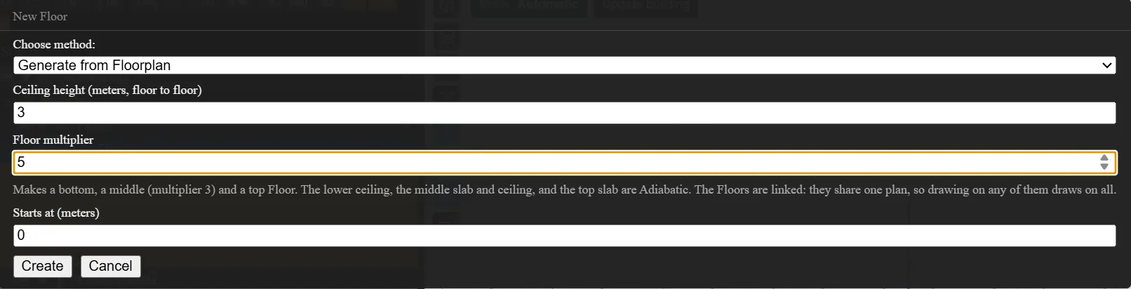
From the New Floor dialog. Click Add Floor in the Building Geometry Outliner’s toolbar. The New Floor dialog asks:
- Choose method: — Create from Scratch (an empty Floor), Copy Existing Floor (offered once some Floor has a Space; Floor to copy chooses which), or Generate from Floorplan.
- Ceiling height — floor to floor. The default is the ceiling height of the highest Floor in the model.
- Floor multiplier — how many identical storeys the Floor stands for; default 1 (§6.2).
- Starts at — the elevation of the bottom of the new Floor. The default is the top of the highest Floor in the model (its elevation plus its ceiling height), or 0 for the first Floor.
Click Create. With Generate from Floorplan, EP3 then asks for the drawing file, makes an empty Floor, imports the drawing onto it, and opens the Floor from Drawing steps. The values from the dialog fill the Place step, where they can still be changed. If the file is an image, or a PDF page imported as an image, it is imported and the status line says that Floor from Drawing could not start; the empty Floor stays.
From a drawing already in the model. A CAD floor plan in the outliner’s Floor Plans section has a ▤ button, Create Floor from Drawing…. The button is greyed out, with the reason as its tooltip, when the drawing is an image, when another Floor from Drawing session is open, or while Position Background is running. The drawing’s Floor must be empty: on a Floor that already has geometry, the tool does not start. The ✕ on a drawing’s row asks “Delete <drawing>?” before it deletes the drawing (Delete or Cancel); the delete is one undo step. Use the eye buttons to hide drawings.
A panel opens at the right of the 3D view. Its header shows the step (“Step 4 of 7: Place”) and the drawing’s name. Back and Next move between steps, and Cancel closes the session and undoes everything it did. On Scale and turn, Crop, Layers, and Place, Tab and Enter go to the next step and Shift+Tab goes back, when no field is being typed in.
3. Scale and turn
The first step checks the drawing’s size and turns it the right way round, before anything is cropped or hidden. While this step is open, and during any Position… run started from Floor from Drawing, every layer of the drawing is shown and can be snapped to, and the crop box is ignored, so a scale bar or a dimension outside the plan can be used. The layers and crop box saved with the drawing are unchanged; from Crop on they apply again.
The scale line says what the drawing’s size rests on:
- “True size, from the drawing’s own units.” — a DXF or DWG, which is drawn to scale.
- “Scale 1:100, from the page’s text.” — a PDF page whose text gives the scale. “Scale 1:100, as typed on import.” when the scale was typed in the Import PDF Page dialog.
- “Scale 1:100, a guess from the wall thickness. Check it.” or “Scale 1:100 assumed: the page does not say. Check it.” — a PDF page whose text gives no scale. These lines are amber, and the scale should be checked.
- “Scale set by measuring a known length (about 1:80).” — after Check scale.
The buttons:
- Check scale: measure a known length — click the two ends of a length you know on the drawing (a scale bar, a grid spacing, a dimension), type the true length, and press Enter or Tab. The drawing is scaled and the panel returns on this step. Cancel in the bar takes back the measurement only.
- Turn 90° left and Turn 90° right — turn the drawing a quarter turn about its centre.
- Position… — moves the drawing: click a point on it, then the point on the building (or the origin) where it belongs, with snapping to every layer. Only this position step of Position Background runs (Creating Building Geometry); Cancel in the bar takes back that move only.
A DXF or DWG that reads the right way needs nothing here: click Next.
4. Crop
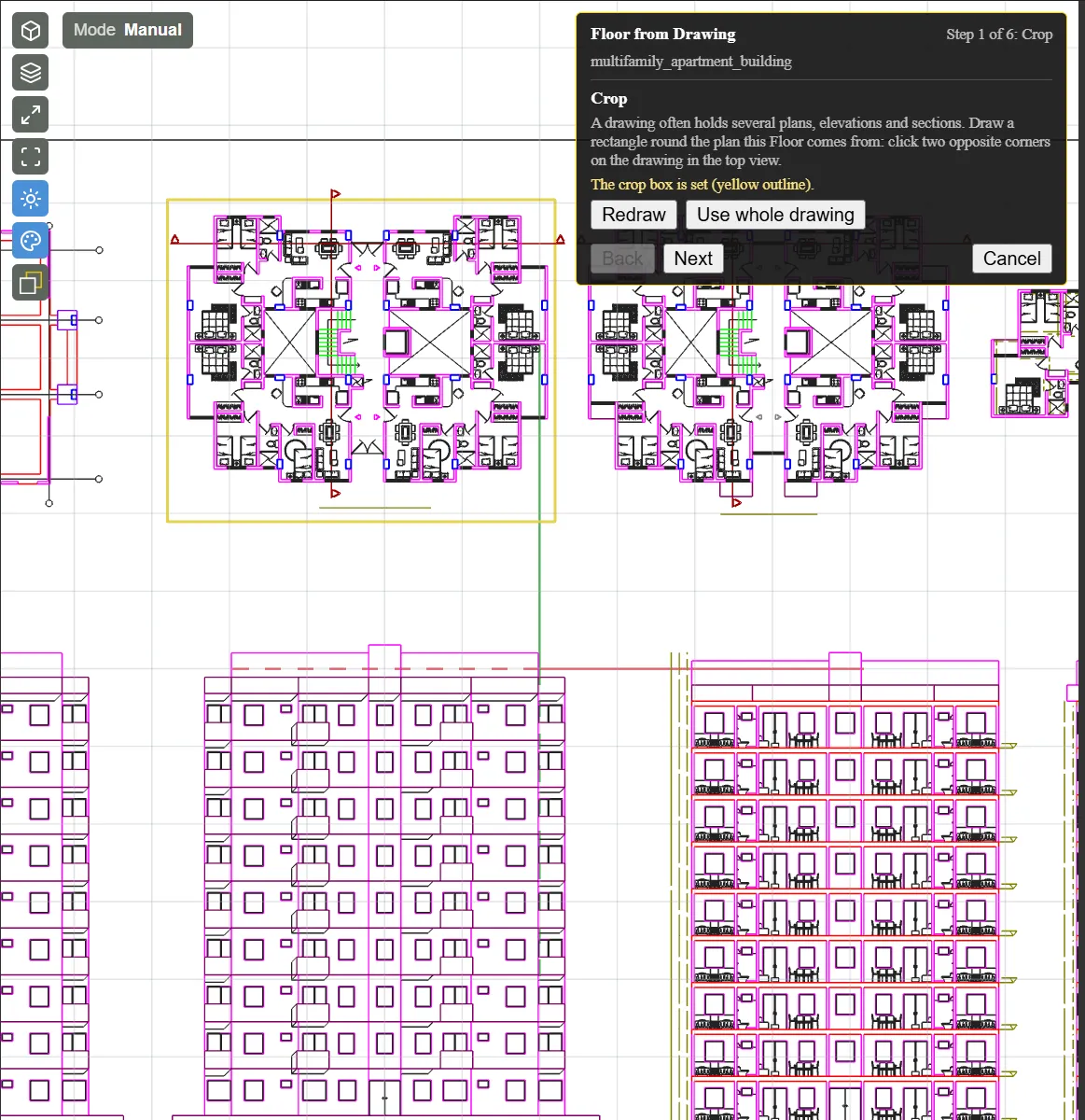
A drawing file often holds several plans, elevations, and sections on one sheet. On Crop, click two opposite corners of the plan this Floor comes from, in the top view. The crop box appears as a yellow outline. Redraw starts the box again, and Esc takes back the first corner. Use whole drawing removes the box and uses every line on the visible layers.
The crop box is saved with the drawing.
5. Layers
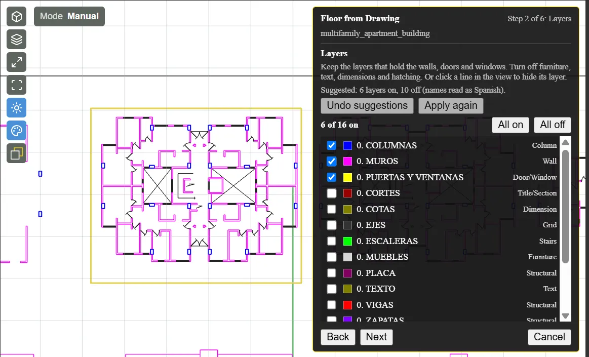
EP3 reads walls, doors, and windows from the drawing’s lines. Layers lists every CAD layer with a checkbox, the layer’s color, and a role EP3 read from its name (walls, doors, windows, furniture, text, and so on, in English, Spanish, French, German, Portuguese, Italian, and Dutch). The step opens with EP3’s suggestion already applied: the layers that look like walls, doors, and windows on, and furniture, text, dimensions, and hatching off. The note under the buttons says how many layers are on.
- Undo suggestions puts the layers back as the file had them.
- Apply again applies the suggestion again after you have changed layers by hand.
- All on and All off switch every layer.
When another floor plan in the model has already been through this step, the layers follow that drawing by name: a name it had keeps its choice, and a new name gets the suggestion. The note reads “Matched the layers of <drawing>”. Suggest only ignores the other drawing and uses the names alone.
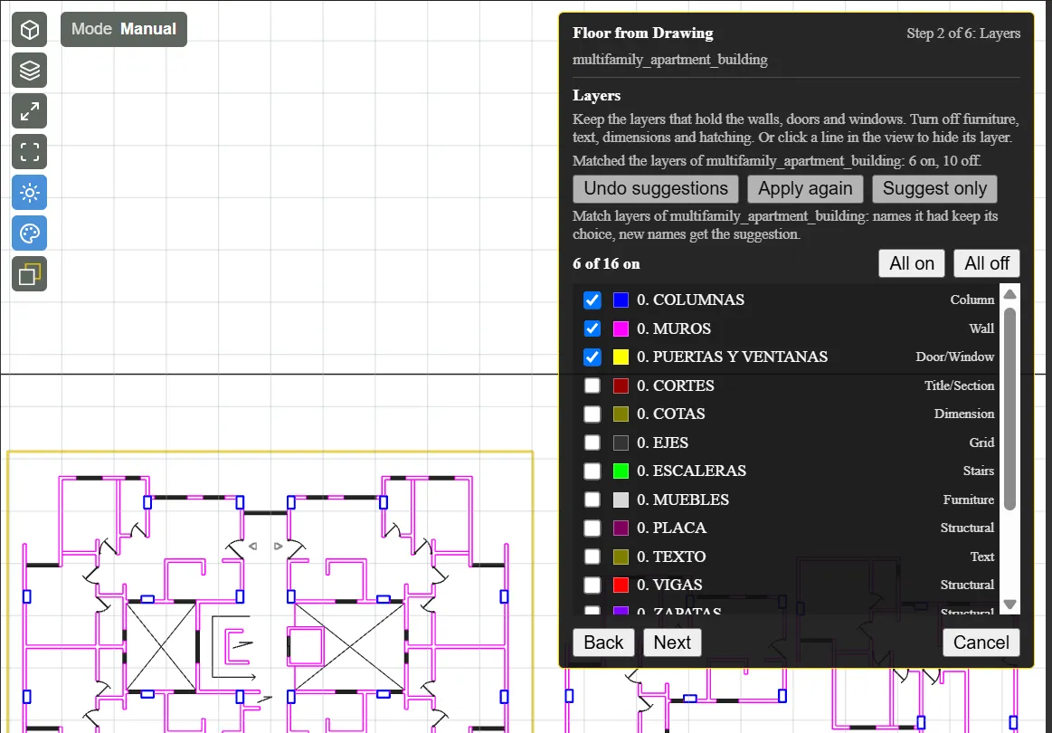
Layers that are off are not read as walls. The text on them is still read later, for the Space names on Names and types (§9).
6. Place
6.1 Placing the drawing
The drawing’s main walls must be square to the model’s X and Y axes. The automatic placement moves a drawing but never turns it: turn a plan on Scale and turn (§3). The step repeats that step’s scale line, read-only, with a Back to Scale and turn button.
When another Floor in the model has Spaces, EP3 places the drawing automatically. It matches this plan’s exterior walls against the exterior walls of the Floor directly below the new Floor’s Starts at elevation (or, if there is none, the nearest Floor above) and moves the drawing to the best match. The panel shows:
- Stack on <Floor> with the score, for example “Exterior walls: 96% coincide with Floor 1.”
- “Placed at the best match automatically.” with a Take back button that returns the drawing to where it was.
- A legend: the Floor’s outline is drawn blue and this plan’s outline orange.
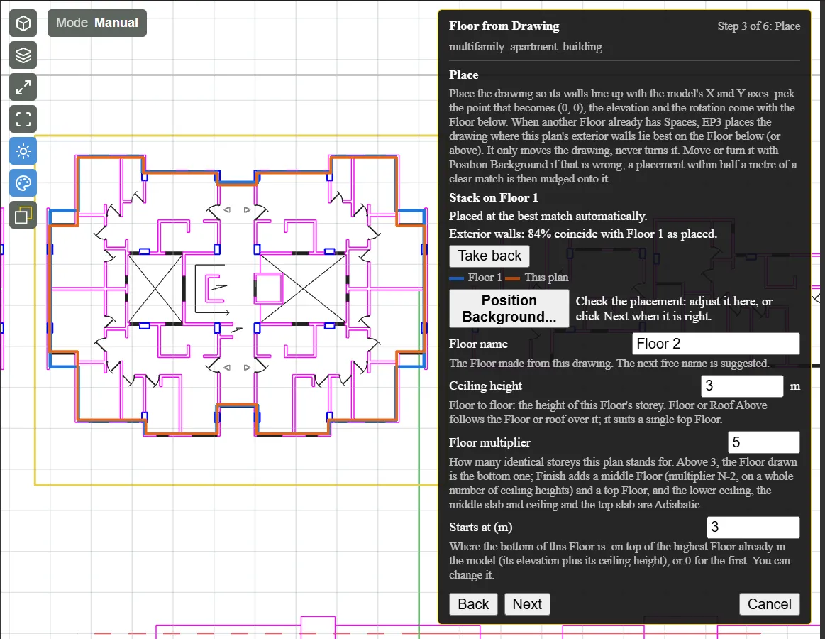
A score under 60% is reported as “Only 34% of the exterior walls coincide with Floor 1: a different footprint?” and the drawing is still placed there. If the plan’s walls run at an angle to the other Floor’s by more than 0.1 degree, the panel says so; turn the plan on Scale and turn.
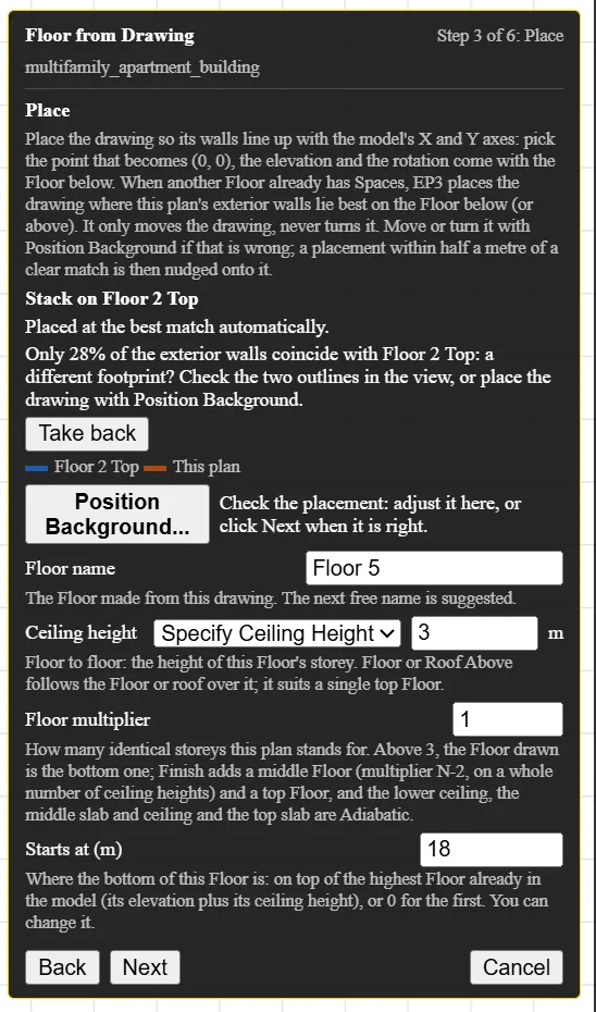
The automatic placement happens once for each set of inputs (the drawing, its layers, the crop, the settings, and Starts at). A placement you make afterwards stays.
Click Position… to check or change the placement: click a point on the drawing, then the point on the building it should go to. It runs only the position step; the scale and the turn are set on Scale and turn. When you finish with the drawing moved, EP3 looks for a shift of up to 0.5 m that lines the exterior walls up with the Floor below or above, and applies it when it gives a clearly better match. The panel reports it, for example “Nudged 0.12 m east to line up with Floor 1’s exterior walls (62% to 96% coincide).”, with a Take back button that restores your placement exactly.
When no other Floor has Spaces, there is nothing to match against; place the first Floor’s drawing with Position…, for example by putting a corner of the plan on the origin.
6.2 Ceiling height, Floor multiplier, and Starts at
The step’s fields repeat the New Floor dialog:
- Floor name — the next free name (“Floor 2”) is suggested.
- Ceiling height — with a Floor multiplier of 1 you can choose Floor or Roof Above (the walls rise to the Floor or roof above, which suits a single top Floor) or Specify Ceiling Height, floor to floor.
- Floor multiplier — a whole number, 1 or more.
- Starts at — the elevation of the bottom of the Floor.
A Floor multiplier above 1 stands the drawn plan in for several identical storeys. The Floors it needs are made at Finish, with the same stacking the Model Wizard uses (The Model Wizard):
| Floor multiplier | Floors made |
|---|---|
| 1 | One Floor, named as typed. |
| 2 or 3 | That many Floors, one ceiling height apart, named “<name> Bottom”, “<name> Middle” (for 3), and “<name> Top”. |
| 4 or more | A bottom Floor, a middle Floor, and a top Floor, named “<name> Bottom”, “<name> Middle”, and “<name> Top”. The middle Floor has a multiplier of the Floor multiplier minus 2. |
The drawn Floor is the bottom Floor; the others are linked to it and have the same Spaces, Space names, and Space Types. Each of their Zones is are named “<Floor> <Space> Zone”, for example “Typical Middle Apt 1 Zone”. In a stack of four or more, the middle Floor sits a whole number of ceiling heights above the bottom Floor, so that its elevation is a storey line: the Floor multiplier minus 1, halved and rounded down (1 for a multiplier of 4, 2 for 5 or 6, 3 for 7 or 8). The top Floor sits (Floor multiplier minus 1) ceiling heights above the bottom. The bottom Floor’s ceiling, the middle Floor’s slab and ceiling, and the top Floor’s slab use an Adiabatic copy of the interior floor and ceiling construction, because those surfaces would touch the Floors that the multiplier replaces. Every Floor of a stack needs a set ceiling height, so with a Floor multiplier above 1 the Ceiling height field takes a number only.
The Floors of a stack share one plan, its Spaces, and their windows, doors, and wall paint, so an edit on one Floor is made on all of them. §3.3 of Building Geometry describes what is shared and how to unlink a Floor.
7. Exterior walls
On entering this step EP3 finds the building’s outline in the drawing and writes it onto the Floor as real space-boundary edges, in the same style as edges drawn by hand. The drawing is dimmed underneath. A closed outline gets a face. An angled or curved facade becomes straight sides at the angles drawn, following the wall; interior walls stay square. If the building has several separate parts, each is an outline; with more than one, each outline’s number is drawn on the plan, and the status line reads “2 outlines closed”.
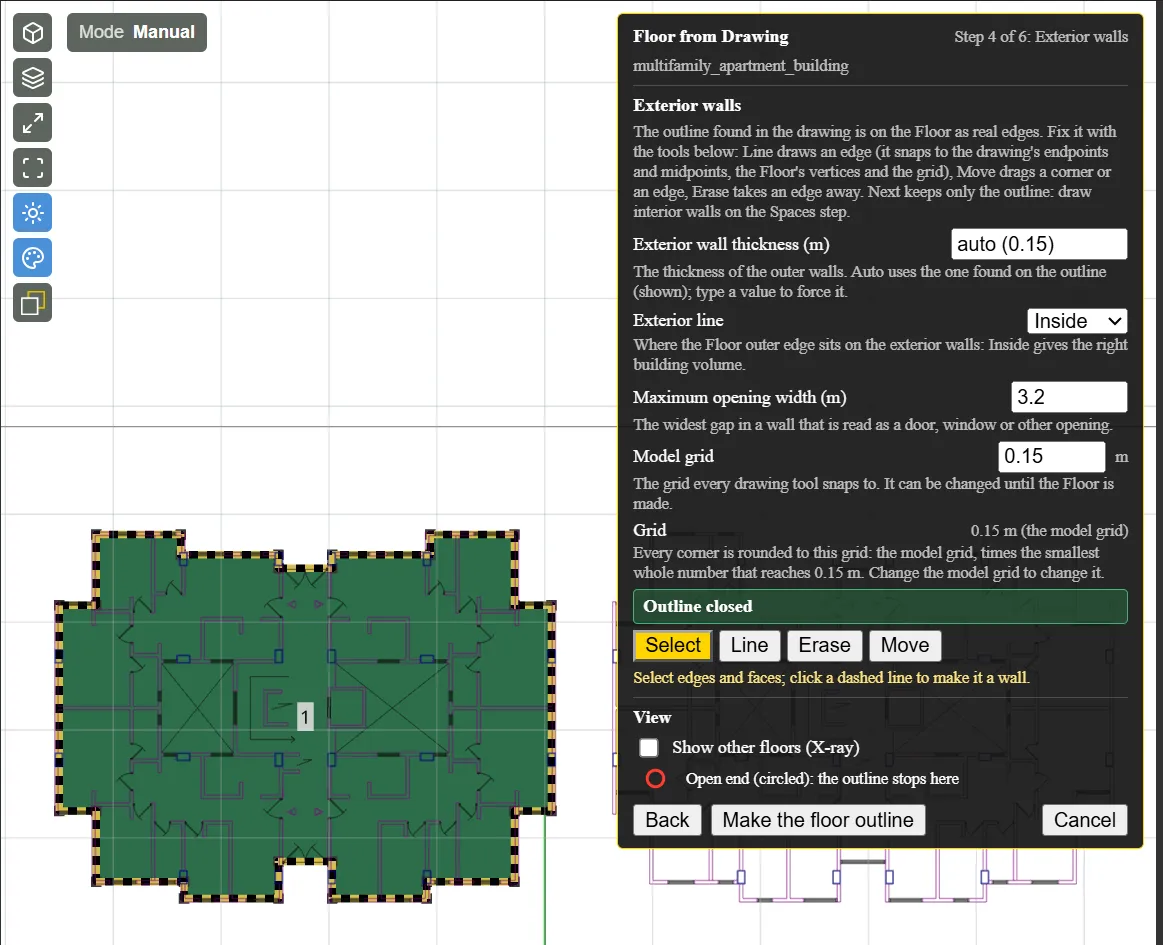
The status line under the settings says what the outline needs:
- “Outline closed” — the outline can go on.
- “The outline has 3 loose ends (circled); Next removes them.” — each loose end is circled. They are removed when you click Make the floor outline.
- “No closed outline yet: draw the building outline with Line” — the drawing did not give a usable outline. Draw the outline with Line.
- “The outline is open: draw the missing sides with Line, from circled end to circled end.” — EP3 wrote the sides it found, but the drawing left gaps in the outline. The open ends are circled.
Walls shown inside the outline on this step are only a guide. The Spaces step finds the interior walls again from the drawing, so no Spaces are made from them yet, and the outliner lists none until you finish.
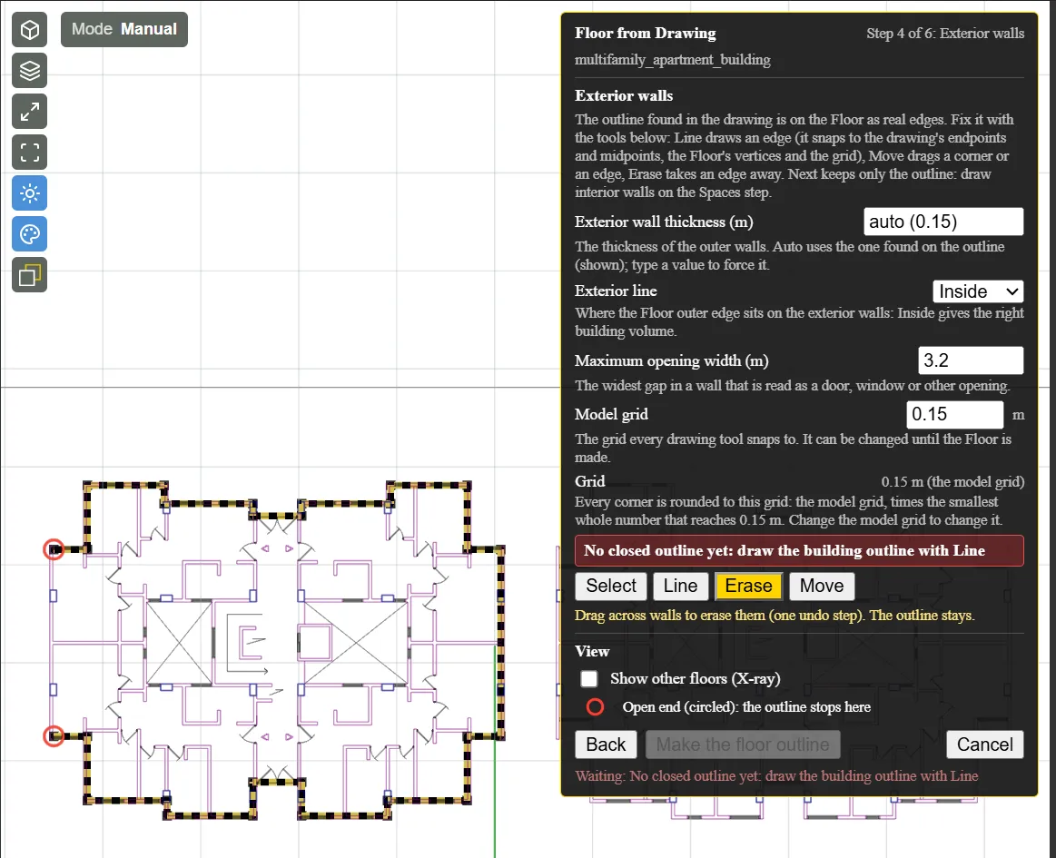
Fixing the outline. The tools are Select, Line, Rectangle, Erase, and Move, the same tools used elsewhere in EP3, with the same snapping: to the drawing’s line ends and midpoints, to the Floor’s vertices, and to the grid. Use Line to draw a missing side (or Rectangle to draw four at once), Move to drag a corner or an edge, and Erase to take an edge away. Each tool action is one undo step. Where an exterior side of the new plan lies within two grid steps of a parallel exterior side of the Floor below or above, it is moved onto that side as you draw or move it, in the same undo step, so the walls stack.
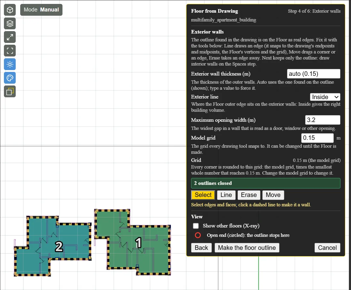
Settings. The settings change how the outline is found:
- Exterior wall thickness — auto shows the thickness found on the outline; type a value to force it.
- Exterior line — where the Floor’s outer edge sits on the exterior walls: Inside, Centre, or Outside. Inside gives the building’s true interior volume.
- Maximum opening width — the widest gap in a wall that is read as a door, window, or other opening.
- Model grid — the grid the drawing tools snap to. It can be changed until the Floor is made.
- Grid (read-only) — the grid Floor from Drawing rounds every corner to: the model grid, times the smallest whole number that reaches 0.15 m (about 6 in). A model grid finer than 0.075 m (about 3 in) cannot be used; the step says so, and Make the floor outline is unavailable until the model grid is changed.
Changing a setting or the model grid finds the outline again from the drawing. If you have edited the outline on this step, the panel first asks “Changing this finds the outline again from the drawing: your edits on this step are discarded.” with Replace my edits and Keep them. A settings change and the outline it replaces are one undo step.
Show other floors (X-ray) shows the Floors below and above while you work.
Click Make the floor outline once at least one outline is closed; any loose ends are removed. EP3 keeps only the outer boundary of each outline and the boundary of any courtyard, so lines drawn inside the outline on this step are removed: interior walls are drawn on the Spaces step. EP3 then makes the Floor: the outline and every interior wall it is confident about, as edges on the grid, and the Spaces they enclose.
8. Spaces
The Floor now exists as real geometry, with the drawing underneath in grey. The step is ordinary Floor editing, with a panel that adds the maybe walls, clean-up, and settings described below. The summary line reads, for example, “46 Spaces, 1 void, 21 dangling ends”. Hover a Space or click it to see its name and area in the panel; the Space’s dialog does not open while the session runs.
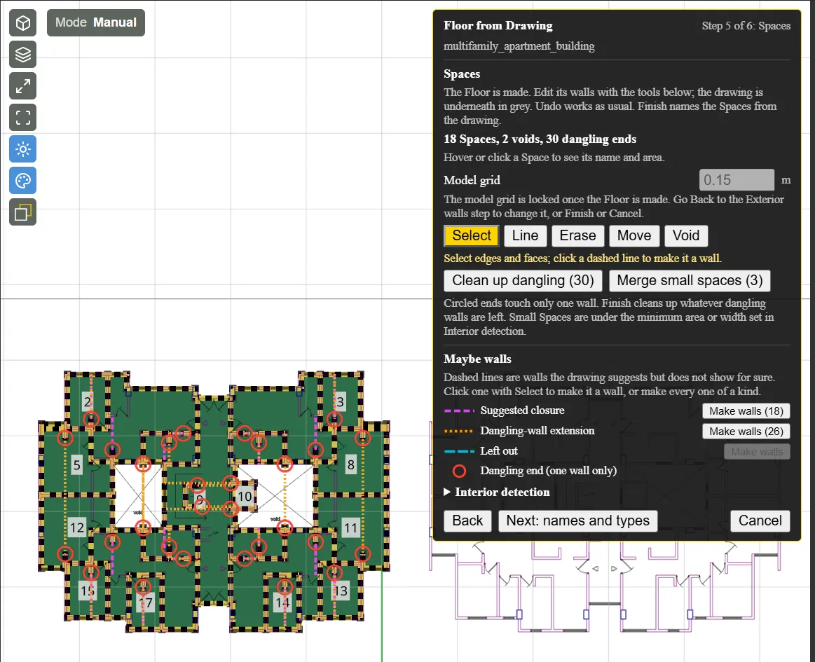
8.1 Tools
- Select — selects edges and faces. Clicking a dashed maybe wall makes it a wall (§8.2).
- Line — draws walls. A line that runs outside the outline is cut back to it, and one drawn wholly outside is removed.
- Rectangle — click one corner, then the opposite corner, to draw four walls at once. They snap as Line does, a side that runs outside the outline is cut back to it, and the rectangle is one undo step.
- Erase — drag across walls to erase them; one sweep is one undo step.
- Move — moves walls and corners inside the outline.
- Void — click a Space to make it a void, which has no Space and no floor face. Click a void to make it a Space again. Esc leaves the tool.
The outline is locked. An edit that would leave any part of it without an edge is refused, and the status line gives the reason. To change the outline, go Back to Exterior walls.
Each edit is one undo step, and Undo works as usual, back as far as the point where the Floor was made.
8.2 Maybe walls and dangling ends
A dangling end is a wall end that touches one wall only. Dangling ends are circled. Clean up dangling (n) removes every wall run that ends in a dangling end, repeatedly, until none remain. It never removes an outline edge and is one undo step. Finish also removes any dangling walls left.
Maybe walls are dashed lines EP3 suggests but the drawing does not show for certain. There are three kinds, each a different color, listed in the panel with a sample of the line:
- Suggested closure (magenta) — a gap with nothing drawn in it, up to the Maximum opening width.
- Dangling-wall extension (orange) — a free wall end carried along its line to the wall it meets.
- Left out (cyan) — a small group of walls that EP3 dropped when it found the outline and interior.
Click a maybe wall with Select to make it a wall exactly where it is drawn, or click Make walls (n) beside a kind to make all of that kind in one undo step. When a converted wall would end in a dangling end that lies within two grid steps of another wall, the end is carried along its line onto that wall. A maybe wall that runs beside a real wall, parallel and closer than a wall thickness, is not offered. Single-line walls and openings with no door or window symbol are not found as walls and leave dangling ends; the Dangling-wall extension kind closes most of them.
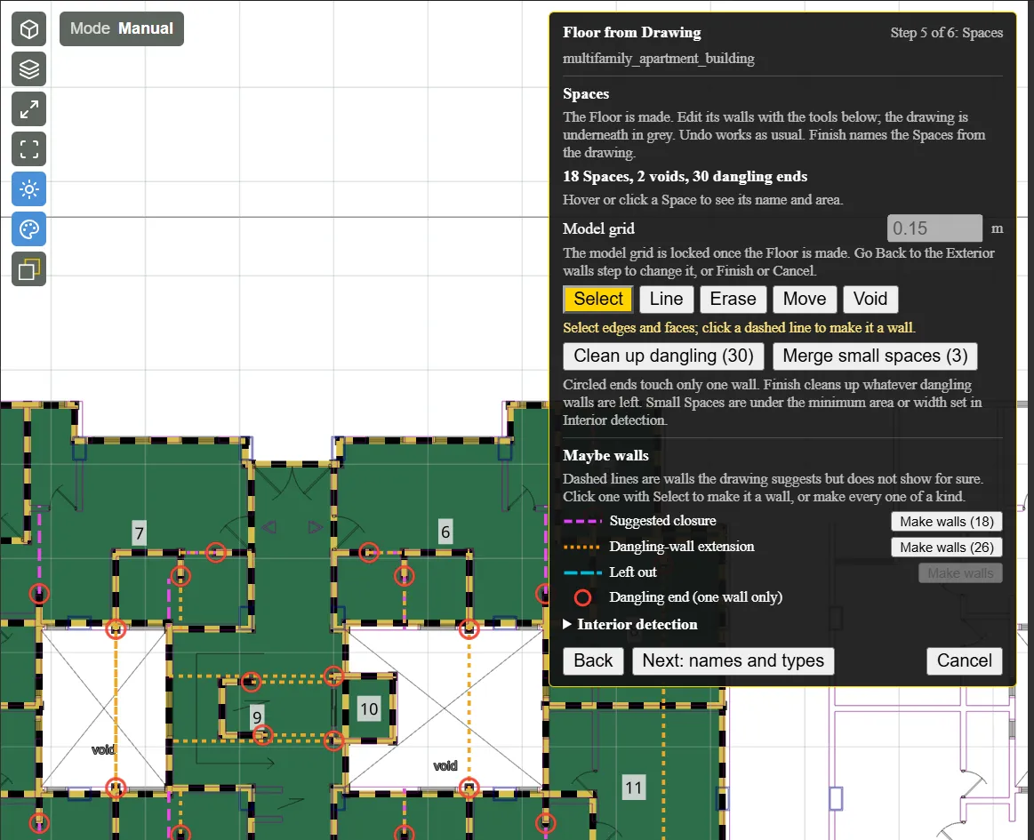
8.3 Small Spaces and voids
Two parallel walls closer together than a wall thickness are treated as one wall, so no sliver Space forms between them. The thickness used is the thickest wall found (up to 0.6 m), and at least two grid steps.
Merge small spaces (n) joins every Space smaller than the Minimum Space area or narrower than the Minimum Space width to the neighbouring Space it shares the most wall with, smallest first, then removes the dangling walls that remain. It never crosses the outline, a void is not a neighbour, and a Space with no neighbouring Space stays. It is one undo step and runs only when you click it, so a real closet or shaft under the minimum is never merged without your seeing it. The defaults are 5 m² (about 54 ft²) and 0.9 m (about 3 ft), the width raised to a whole multiple of the grid.
A room crossed by an X in the drawing, as for a shaft or a light well, is a void when the X marks cover at least 30% of the room. Under 75% only the marked box is the void and the rest of the room stays a Space; from 75% the whole room is the void. An X drawn as four strokes from the corners to the middle counts as an X.
An X-marked shaft or light well often opens into the room beside it through a window or door gap, so the finder sees one room that the X covers less than 30% of. When walls stand along at least 60% of the X’s box, with some wall along every side, the box is still made a void and the rest of the room stays a Space. A box with one side wholly open, such as a light well open to a corridor, stays part of that room: draw a line across the opening with Line, then click the light well with Void.
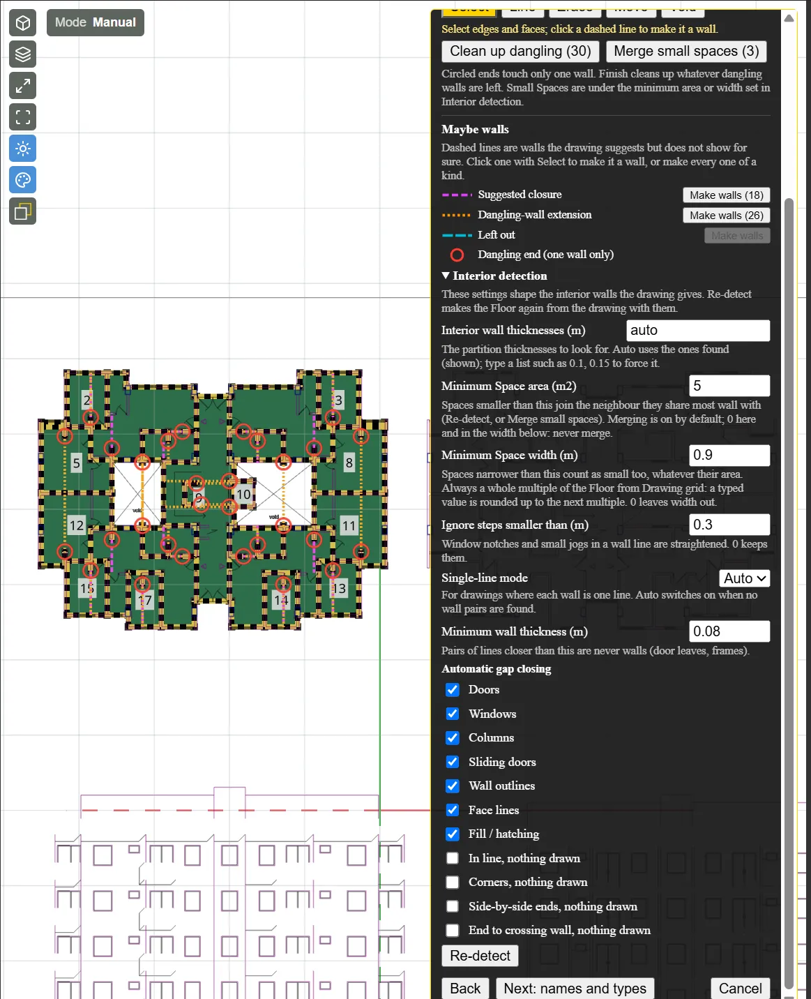
8.4 Interior detection and Re-detect
The collapsed Interior detection section holds the settings that shape the interior walls: Interior wall thicknesses (auto, or a list such as 0.1, 0.15), Minimum Space area, Minimum Space width, Ignore steps smaller than (window notches and small jogs in a wall line are straightened), Line up walls (found interior walls nearly in line, up to two grid steps apart, move onto one line; lines you draw never move), Single-line mode (for drawings where each wall is one line), Minimum wall thickness, and Automatic gap closing, a checkbox for each kind of gap: Doors, Windows, Columns, Sliding doors, Wall outlines, Face lines, Fill / hatching, and the gaps with nothing drawn (In line, nothing drawn, Corners, nothing drawn, Side-by-side ends, nothing drawn, End to crossing wall, nothing drawn).
Re-detect makes the Floor again from the drawing with the current settings. It replaces every edit made on this step and keeps the outline, and it asks first: “Re-detect makes this Floor again from the drawing: every edit you made on the Spaces step is replaced. The outline stays.” Choose Replace my edits or Keep them. The model grid is locked from this step on, because the Floor’s edges are on the grid it was made with.
8.5 Coverage
After the outline is made, an area inside it loses its Space only when you mark it Void. Within the outline, Spaces and voids always cover the whole area, whatever you do on this step: erasing an interior wall merges the two Spaces beside it, a new line splits one, and moving a wall keeps the coverage. If detection finds nothing in a region, that region is one Space.
Click Next: names and types when the Spaces are right. EP3 first cleans up the dangling walls, so the Spaces are final.
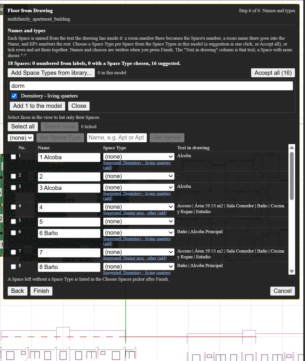
9. Names and types
The last step lists the Floor’s Spaces in a table, one row each, in reading order (top to bottom, then left to right):
- a tick box;
- No. — the Space’s current number, as drawn on the plan and listed in the outliner. Entering the step numbers the Spaces 1 to N in reading order;
- Name — editable. EP3 suggests it from the text the drawing has inside the Space (see below). A name typed in the row is the Space’s name straight away;
- Space Type — a list of the Space Types already in the model, plus (none). A Suggested: link under it chooses the suggested type in one click;
- Text in drawing — the text found inside the Space, with - when there is none. It is read from every layer, including the layers hidden on Layers.
Names. A room or unit number in the drawing’s text becomes the number in the Space’s name, followed by the room’s name: the text “19 GIFT SHOP” gives “19 GIFT SHOP”, and a unit tag such as “UNIT A 290 SF” gives “UNIT A”. A Space with no usable number keeps its current number, or gets the lowest free number when a label took it. A one-letter text is never a name, and a Space holding more than two different texts (fixture notes, for example) takes its number only. Names never collide on a Floor. A typed name that another Space on the Floor already has is outlined in red, and Finish waits until it is changed.
Space Types. EP3 matches the words in each Space’s text to a room category (office, corridor, restroom, storage, stair, elevator, mechanical, kitchen, bedroom, lobby, and others) in English, Spanish, French, German, Portuguese, Italian, and Dutch. It suggests a Space Type from the model that matches. Only when none matches does it suggest one from the template library, shown as “Suggested: Office (add)”; choosing it adds that Space Type to the model and chooses it.
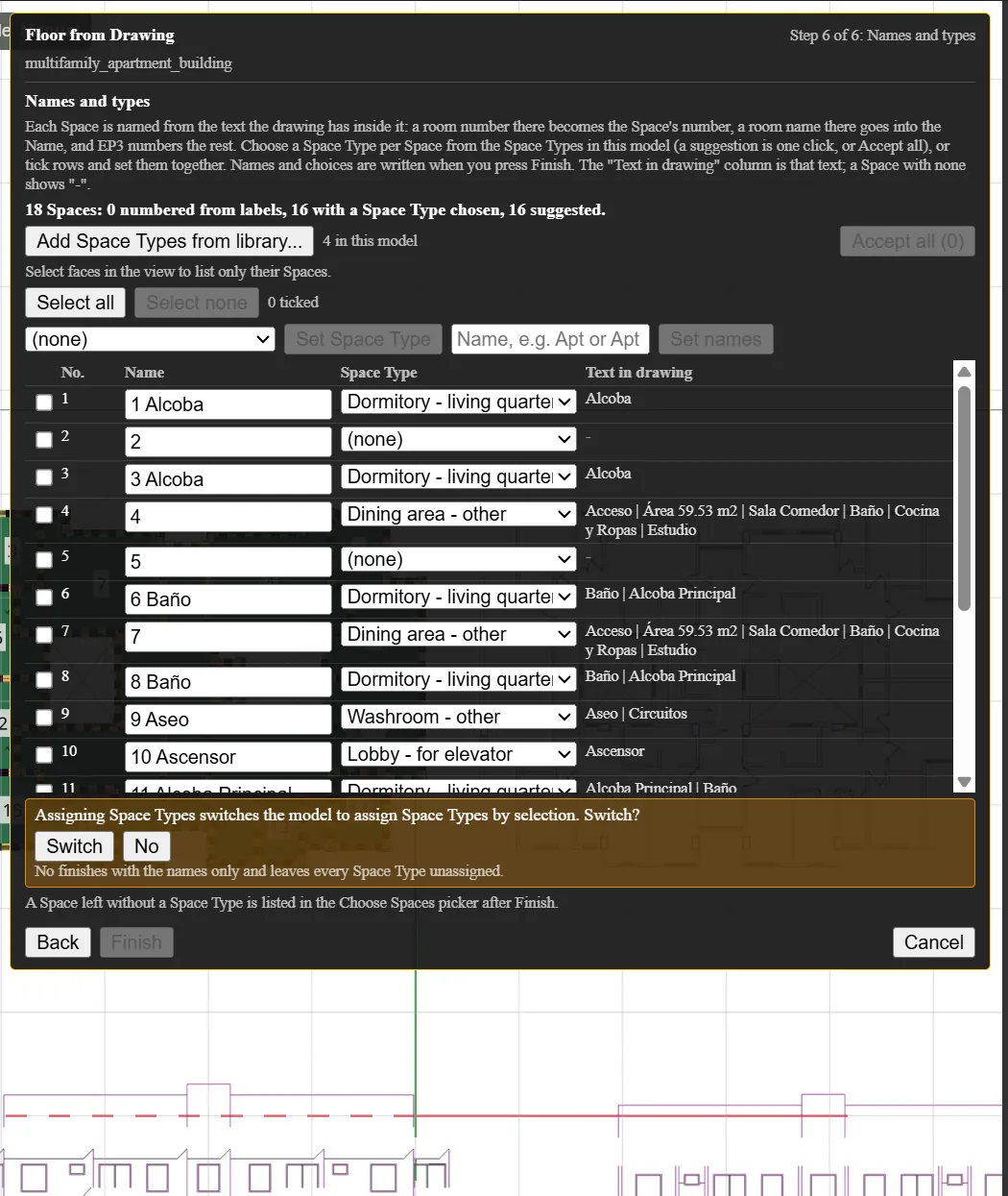
- Accept all (n) chooses every suggested type for the rows shown that you have not decided yet.
- Add Space Types from library… opens a checklist of the library’s Space Types, with a filter. Add n to the model brings the ticked ones in, with the EEMs of the library that change them; they then appear in every row’s list, and the status line reads “Added EEMs: …” after the Space Types. Close closes the list.
- Select all and Select none tick or untick the rows shown. With rows ticked, choose a Space Type and click Set Space Type, or type a name in the box (“Name, e.g. Apt or Apt #”) and click Set names; the box changes nothing until Set names is clicked. A # stands for each Space’s number, so “Apt #” gives “Apt 1”, “Apt 2”. With several rows ticked, a name without # keeps each Space’s number in front: “Apt” gives “1 Apt”, “2 Apt”. With one row ticked, a name without # is used as typed.
- Hovering a row lights its Space in the view. With Select you can pick faces in the view; the table then lists only their Spaces (“Showing 4 of 46 Spaces - selected in the view”), with Show all and Show only the n selected to switch.
Space Types are assigned by hand only in a model set to Selected Template under Update Templates Based On (The EP3 Interface and Model Settings). If you choose Space Types and the model is set to Name, Finish first asks “Assigning Space Types switches the model to assign Space Types by selection. Switch?”. Switch changes the setting and finishes with the Space Types; No finishes with the names only and leaves every Space Type unassigned. A Space left without a Space Type is listed after Finish in the Choose Spaces picker when the model is set to Selected Template.
Click Finish. EP3 writes the Space Types, makes the Floors of a Floor multiplier stack (§6.2), and in Automatic mode grows the walls and roofs once. The whole session, from Scale and turn on, is one undo step, “Create <Floor> from drawing”. Back returns to Spaces, and the table’s edits are kept while the Spaces stay as they are.
10. While Floor from Drawing is open
While the session is open, the rest of EP3 is read-only so that the Floor being made cannot be changed from elsewhere. A refused action changes nothing, and the status line says “Finish or Cancel Floor from Drawing first.”; a greyed-out control gives the same message as its tooltip.
- Allowed: panning, zooming, orbiting, 2D and 3D views, X-ray, units, grid and snap switches, Space names, isolation, the eye buttons, Measure, Select, the Handbook, Settings, and the results viewers.
- Tools: Select, Orbit, and Measure always. Line, Rectangle, Erase, and Move on Exterior walls and Spaces only. Void on Spaces. Every other tool and its key is refused.
- Outliner: visible, but nothing in it can be renamed, deleted, added, entered, or switched on or off in an EEM. Expanding and collapsing other rows, the eye buttons, and selecting a Space on another Floor still work. The Floor being made stays collapsed, with a muted “Floor from Drawing” tag; its expand toggle is dimmed, with the tooltip “Spaces are listed when Floor from Drawing finishes”.
- Dialogs: none opens while the session runs, other than viewers.
- Atlas, import, simulation, and the PRM: unavailable. File New, Open, Save, and import are refused. Closing the window asks “Floor from Drawing is open. Cancel it and close?”; Yes cancels the session, taking everything it did back, and the usual unsaved-changes question follows.
- EEMs and mode: the EEM selector and the Automatic and Manual switch are refused.
Undo, Back, and Cancel.
- On Scale and turn, Crop, Layers, and Place, the changes are part of the session, and Ctrl+Z is EP3’s usual undo.
- On Exterior walls and Spaces, every edit is one undo step, and Ctrl+Z and Esc belong to the drawing tools. Undo cannot go back past the point where the Floor was made.
- Back from Spaces takes the Floor away and keeps a snapshot. Going forward again with an unchanged outline restores the snapshot, edits included. A changed outline builds fresh from the drawing, with a note.
- Back from Exterior walls to Place does the same for the outline: it comes back if nothing before it changed.
- Cancel removes everything the session made: the Floor and its Spaces, the crop box, the layer choice, the scale, turns, and placement, and any Space Types added from the library.
11. Several floors
A building’s Floors are made one drawing at a time.
- Make the first Floor from its plan. Choose the typical plan first when one plan stands for several identical floors: the drawn Floor is the bottom Floor of the stack (§6.2).
- For each further plan, use Add Floor and Generate from Floorplan again. Its layers follow the previous drawing’s by name. On Place, EP3 matches its exterior walls to the Floor below, or the nearest above, and its exterior sides snap onto that Floor’s walls within two grid steps, so the walls stack.
- Give a plan that stands for identical floors a Floor multiplier, and its upper Floors are made at Finish.
- For a floor that is the same as one already made, use Copy Existing Floor in the same dialog: it copies that Floor’s geometry, Space names, and Space Types, with no drawing.
Use the same Starts at and Ceiling height values the Floors will have, so that each Floor stands on the one below. Windows from Elevations relies on the Floors standing on storey lines.
12. Windows from Elevations
12.1 Before you start
The tool needs the Building’s Floors, with their walls, and one or more elevations: CAD (DXF, DWG, or a PDF page imported as lines) or an image (§12.5):
- Click + on the Elevations row and choose the file. The Import Elevation dialog takes the direction from the file name (“North.dxf” faces North); check This elevation faces:, tick Mirror drawing if the drawing is drawn mirrored, and click OK (Creating Building Geometry).
- Position each elevation against the building with Position Background, which starts after the import. Two clicks are enough: a point on the drawing, such as a corner of the facade at ground level, and the matching point on the building. The placement can be rough, because matching with the floor plan lines the elevation up (§12.3).
- Click ▦ on the Elevations row, Windows from Elevations…. The button is greyed out, with the reason as its tooltip, when the Building has no CAD or image elevation, when another session is open, or while Position Background is running.
The tool uses every elevation of the Building; a CAD elevation is read whole or inside the crop box the drawing already has. It switches Elevation Wrap on for the session, so each drawing is projected on the walls it faces, and puts your setting back when the session ends.
The panel’s steps are Layers (for CAD elevations), Colours (for image elevations, §12.5), and Preview, followed by Create. Back, Next, and Cancel work as in Floor from Drawing.
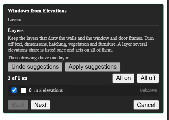
12.2 Layers
Layers is one list for every elevation in the run. A layer name that several elevations share is listed once, with “in 2 elevations”, and switching it acts on each elevation that has it; a layer in only one elevation is listed with that elevation’s name. A checkbox that shows a dash means the layer is on in some elevations and off in others, and a click turns it on in all. All on, All off, Apply suggestions, and Undo suggestions act on every elevation. EP3 applies its suggestion when the session opens.
Keep the layers that draw the walls and the window and door frames. Turn off text, dimensions, hatching, vegetation, and furniture.
The suggestion reads the layer names, and a name can mislead: a layer of window frames may be named for the slabs or the structure. So a layer whose name alone would turn it off as structural (or as ceiling, overhead, mechanical, electrical, or site) is kept on when it holds window frames, that is, when more openings are found with it on than without it (at least 2, and 5%, more). The note under the buttons names such layers, for example “Kept on because they draw window frames: 0. PLACA (66 more openings).” (the openings it adds over every elevation that has it), and their role reads “Structural, frames”. Text, dimensions, hatching, and furniture are never kept on this way.
If an elevation finds fewer openings than you expect, or no doors, a frame layer is probably off: the multifamily facades with their frame layer off give 66 of their 99 openings and no door. Tick the layer and check the counts on Preview again.
12.3 Preview
The preview draws the windows on the walls. Its panel has five sections.
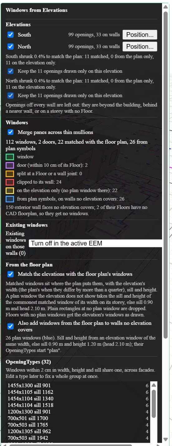
Elevations. Each elevation has a checkbox to take it in or out of the run, a count (“33 openings, 33 on walls”), and a Position… button, which starts Position Background for that elevation. Cancelling there takes back that placement only, and the preview follows the new placement. An elevation that already matches the plan needs no Position…: placing it again can make its match worse. The row’s tooltip says which way the elevation faces: walls facing within 55 degrees of it, and nearest to it, take its windows.
EP3 finds a window as a closed set of thin frame members (7 cm or less wide) around glass, 0.25 to 3.5 m wide and 0.25 to 2.6 m tall. Panes divided by thin mullions are one window. When a drawing has no framed windows at all, every closed rectangle 0.2 to 3.5 m wide and 0.2 to 2.6 m tall on its visible layers is taken as a window, and the row says “(plain rectangles)”. Check those on the walls.
When an elevation gives no windows, the panel says why:
- “no openings were found on its visible layers inside its crop” — the layer with the window frames may be off;
- “no exterior wall faces it within 55 degrees” — check which way the elevation faces;
- its openings are above or below the walls it covers, with the heights — check its height with Position…, or the Floors;
- its openings are off the end of the walls, or fall in gaps between walls or behind nearer walls — check its position with Position….
Openings off every wall, beyond the building, behind a nearer wall, or on a storey with no Floor, are left out.
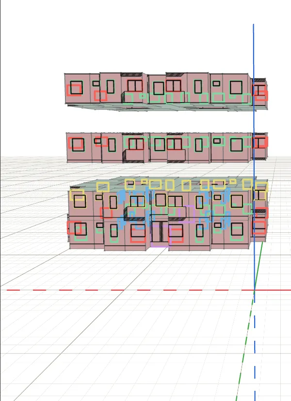
Windows. Merge panes across thin mullions is on by default; turn it off to make each pane a separate window. The counts line reads, for example, “66 windows, 2 doors, 66 matched with the floor plan”. The legend colors the windows on the walls:
- green — a window;
- purple — a door (its bottom within 10 cm of its Floor);
- amber — split at a Floor or a wall joint;
- red — clipped to its wall;
- teal — in the floor plan only: the elevation shows no opening there;
- yellow — on the elevation only: no plan window there;
- blue — from plan symbols, on walls no elevation covers;
- grey — left out because it overlaps a window that stays.
Windows that cross a Floor line or a wall joint are split into one window per wall face, and windows that run past a wall’s edge are clipped to it.
Leaving an opening out. Leave out openings… under the legend lets you click windows on the walls: each click leaves that opening out of the run, every piece of it, and draws it grey and dashed; a second click takes it back. A left-out opening makes no window, and nothing is copied from it to walls no drawing shows. Put all back takes every one back. Use it for a sign, a lamp, a traffic signal, or a stray rectangle the elevation gave as a window.
Storeys an elevation shows no window on. A storey that an elevation covers but shows no window on, above a storey that it does (a top storey hidden behind a cornice, or above the top of a photo), is listed as “<Floor> on <elevation>: copy the storey below (<Floor>)”. Ticked, the storey gets the windows of the storey below, doors left out, at the same height above its Floor and on its own walls. They are drawn light blue, follow the overlap rule below, and are copied on to walls no drawing shows.
Existing windows. Existing windows on those walls (n) chooses what happens to windows already on the walls that get new ones:
- Turn off in the active EEM (the default);
- Erase;
- Keep (add only new windows that do not overlap them).
An opaque door is never replaced. Running the tool again on an elevation is allowed and offers the same choice. Running the tool again on walls that already have windows from an earlier run replaces those windows, including glass doors, according to this choice.
From the floor plan. Two checkboxes, both on by default.
- Match the elevations with the floor plan’s windows. Where a Floor was made from a CAD plan with Floor from Drawing, or has a CAD plan with window symbols, the plan gives each window’s position along the wall and the elevation gives its sill height and its size. EP3 first lines the elevation up with the plan automatically, searching for a shift of up to 3.00 m and a stretch of up to 5% along the facade. The line under the elevation says what it did: “North moved 1.90 m east to match the plan: 44 matched, 0 from the plan only, 0 on the elevation only.” A shift over 0.50 m is applied only when most of the plan’s windows agree on it; when another shift fits almost as well, the line says so and asks for the elevation to be placed within 0.50 m with Position…. A larger correction is refused (“North would have to be moved 17.55 m east and shrunk 0.2% to match the plan, more than 3.00 m or 5%: likely the wrong side or the wrong scale. Its windows are placed as drawn, without matching.”), and that elevation’s windows are placed as drawn. A matched window sits where the plan puts it, with the elevation’s width (the plan’s when they differ by more than a quarter) and the elevation’s sill height and height. A plan window the elevation does not show takes the sill height and height of the commonest matched window of its width on its storey, or a sill of 0.90 m (about 3 ft) and a head of 2.10 m (about 7 ft). A framed opening the elevation draws with no plan window beside it is kept and shown yellow; clear Keep the n openings drawn only on this elevation, under the elevation’s line, to leave them out. A plain rectangle with no plan window is dropped. A Floor with no CAD plan gets the elevation’s windows as drawn.
- Also add windows from the floor plan to walls no elevation covers. Each window symbol in the plan of a Floor gets a window on the walls that no elevation covers. The default sill height is 0.90 m and the height 1.20 m (head 2.10 m) when no elevation window of the same width gives its size. Off, those walls get no windows.
Storey height warning. When the storeys drawn in an elevation are higher or lower than the Floors’ ceiling height, the Preview says so and names the height the drawing has, for example “North: the drawing’s storeys are 3.09 m high, but the Floors’ are 3.00 m.” The warning appears whether or not matching with the plan succeeded. Click Set ceiling height to 3.09 m to give the Floors that ceiling height; the Floors above move up with it, and their walls are grown again at the new height straight away. The Preview refreshes and the warning goes. The change is part of the session: Cancel takes it back, and it is in the one undo step Create makes.
No two windows overlap or touch. Where two would, EP3 keeps a matched window first, then one the elevation draws, then one from the plan, and drops the other; nothing is trimmed. Windows keep at least 1 mm apart, so a window that would share an edge with another is dropped in the same way. Panes split at a mullion stop 1 mm short of its centre line.
OpeningTypes. The list shows the OpeningTypes the windows will use. Windows within 10 cm in width and height and within 2 cm in sill height share one, across facades. The type takes the group’s average size, scaled so the group’s window area is unchanged, and each facade’s window area changes by less than 2% of its wall area: where a group would change it by more than 1%, EP3 splits the group with a tighter tolerance, down to 2 cm, and below that only while the change is over 2%. Window area by facade lists the change. Names read from the size, such as “1200x1500 sill 900”, “plan …” for plan-only windows, and “door 2000x2200” for doors. Edit an OpeningType later to change a whole group at once (Windows, Shading, and Daylighting).
Walls no drawing shows. Exterior walls that no elevation or plan gives a window are listed in their own section of the Preview, grouped by facing direction. Each facade copies the windows of a facade that has them (mirrored, the default when the opposite facade has windows), takes a window-to-wall ratio, or gets none. The windows are pink, labelled “assumed”, and made again when the tool runs again (Buildings and Surroundings from Maps). Adiabatic walls never get a window.
12.4 Create
Create makes the windows and their OpeningTypes in one undo step. It is unavailable while the preview works out the windows, and says “No windows to make.” when there are none. Cancel takes back the layers, the placements made with Position…, and any ceiling height set from the storey height warning.
12.5 Image elevations
A photo, a rendering, or a scanned elevation takes part in the same run. Where a CAD elevation has Layers, an image has Colours: you pick the colours of the windows, walls, and doors, and EP3 finds the openings from them. From the Preview on, an image elevation works as a CAD one. A photo taken at an angle is first straightened with pins in Position Background. Buildings and Surroundings from Maps covers both steps.
13. Glass doors
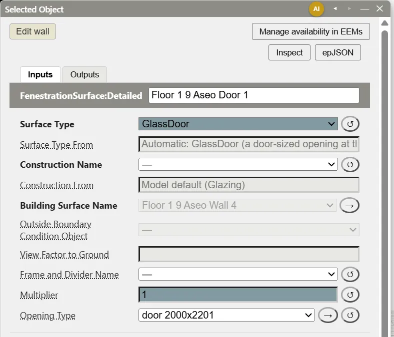
Windows from Elevations makes a door from each opening whose drawn bottom is within 10 cm of its Floor, above or below, such as an entrance door in the elevation or the plan. The door has a sill height of 0 and an OpeningType named for its size, such as “door 2000x2200”.
EP3 sets a window’s Surface Type automatically from its shape and construction. A window with a glazing construction is a GlassDoor when its bottom is within 10 cm (4 in) of the bottom of its wall, it is 1.9 to 2.7 m (about 6 ft 3 in to 8 ft 10 in) tall, and it is 0.6 to 2.6 m (about 2 ft to 8 ft 6 in) wide; any other glazed window is a Window, and an opening with an opaque construction is a Door. A door that Windows from Elevations makes is therefore a glass door when its height and width are in these ranges. You can change a window between Window and GlassDoor in its dialog (Windows, Shading, and Daylighting).
A glass door counts as fenestration everywhere EP3 measures windows: the window-to-wall ratio, the Performance Rating Method’s vertical fenestration, and daylighting apertures. An opaque door does not. A new glass door is named “<Space> Door n”.
14. Troubleshooting
- The outline has loose ends or is open. The drawing’s walls do not meet. Increase Maximum opening width on Exterior walls if a gap is a door or window, turn on the layer that draws the wall, or draw the missing side with Line.
- Only a small part of the building was found. A layer that holds walls is off, the crop box cuts the plan, or a wall is drawn as single lines. Check Layers and Crop, and set Single-line mode under Interior detection for single-line walls.
- Many small Spaces after Make walls (n). Click Merge small spaces.
- A Space is missing, or a shaft shows as a Space. Use Void to remove the Space, or click a void to restore it.
- The windows land on the wrong walls, or matching is refused. The elevation faces another way, is mirrored, or is more than 3 m out of place. Click Position… beside it on the Preview, and read the line under the elevation.
- Windows from Elevations says the elevation would have to be stretched too far. The plan and the elevation were drawn at different scales. Scale the elevation with Position Background, or turn off Match the elevations with the floor plan’s windows.
This handbook is also built into EP3 (Help), where its EnergyPlus links open the EnergyPlus Reference. Technical specifications · Book a demo