Constructions and Materials
1. Overview
Every surface in an EP3 model (walls, roofs, floors, doors, windows) has a construction: the layered assembly, or for a few specialized cases a single rated value, that sets its thermal performance. Constructions are listed in the Constructions panel below the Building Geometry Outliner, where each shows its color in the 3D view and its R-value. You assign a construction to geometry by painting it (Creating Building Geometry), and edit it in the Selected Object dialog: double-click it in the Constructions panel.
A construction’s Construction Type decides which EnergyPlus object it becomes and which fields it has:
| Construction Type | What it represents |
|---|---|
Construction:Opaque |
An opaque assembly: a stack of material layers, outside to inside, exported as a Construction. |
Construction:Glazing |
A glazing assembly: a stack of window material layers, exported as a Construction. |
Construction:FfactorGroundFloor |
A slab-on-grade or other ground-contact floor, characterized by an F-factor in place of a layer stack. |
Construction:CfactorUndergroundWall |
A below-grade wall, characterized by a C-factor in place of a layer stack. |
Construction:ComplexFenestrationState |
A BSDF-based fenestration construction for complex shading and glazing systems. |
Construction:WindowDataFile |
A construction read from a Window5 or Window6 data file. |
Construction:AirBoundary |
A boundary between zones with no thermal resistance, optionally mixing air across it. |
This chapter covers creating and editing constructions, their material layers, F-factor and C-factor constructions, and saving constructions as a library. The default construction for each surface category, which new geometry takes, is set in Model Settings > Default Constructions (The EP3 Interface and Model Settings). Placing windows and doors, and the shading and daylighting controls attached to them, are covered in Windows, Shading, and Daylighting.
1.1 Constructions in EEMs
Every EP3 model has a base model, Global, and any number of Energy Efficiency Measures (EEMs) that change it (Energy Efficiency Measures (EEMs)). Constructions can differ between EEMs in two ways:
- Change the construction. In an EEM, edit the construction’s fields or layers: change a layer, a material’s thickness or resistance, or the F-factor, C-factor, or glazing values. Every surface that uses the construction changes together. To add wall insulation in an EEM, for example, select the EEM and raise the thermal resistance of the exterior wall’s insulation material.
- Paint a different construction. In an EEM, paint surfaces with another construction. Paint belongs to the active EEM (Creating Building Geometry), so the surfaces keep their Global construction everywhere else. The painted surfaces flash in the 3D view to show the change is in the EEM; painting with Default resets them to inherit and does not flash (Energy Efficiency Measures (EEMs)).
Use the first when an assembly changes wherever it is used, and the second when particular surfaces get a different assembly from the rest. To load a whole upgraded set of constructions into an EEM at once, use Populate Constructions (§9).
2. Creating and editing a construction
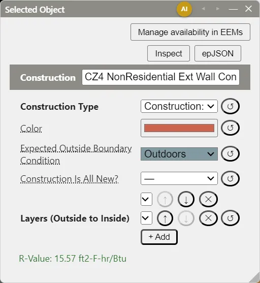
+ New, in the Constructions panel, creates a construction (named Construction 1, Construction 2, and so on), opens it in the Selected Object dialog, and makes it the Paint tool’s construction. Its fields:
- Construction Type — see §1. Changing the type reclassifies the construction in place; every surface painted with it keeps it.
- Color — its color in the 3D view and the Constructions panel.
- Expected Outside Boundary Condition — the boundary the construction is meant for:
Outdoors,Surface(an interior partition),Ground,GroundFCfactorMethod,Adiabatic, orAny. It groups the construction in the Constructions panel, decides which Default Constructions slots it may fill (§8.1), and sets the boundary of a surface whose geometry does not decide it (a surface painted with anAdiabaticconstruction becomes adiabatic, for example). Model Validation’s Unexpected Construction Types check flags a surface whose boundary differs from its construction’s. An imported construction takes its type from the file’s surfaces (Importing EnergyPlus Files). - Construction Is All New? — used by the ASHRAE 90.1 PRM generator to tell new construction from existing.
- Layers (Outside to Inside) — the material layers, for
Construction:OpaqueandConstruction:Glazing(§3). + Add adds a layer, + No-Mass layer and + Simple Glazing add the layers described in §3.2, the arrows reorder layers, and ✕ removes one.
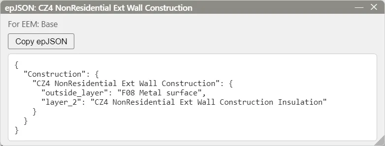
The dialog shows the construction’s R-value below the fields, and its epJSON button shows the Construction object it exports, with its layers in order.
2.1 Changing the Construction Type
Because the type is a field of the construction, you can change it at any time without repainting. The one exception: a construction that is a collection’s Construction, a Default Constructions slot other than Glass, or painted on a floor face (or on a wall or roof face whose collection has no construction) can’t become a see-through type, since those surfaces can’t be glazed. EP3 refuses the change and says where the construction is used; make a separate window construction instead. Wall and roof faces painted with it are glazed when it changes (Creating Building Geometry). Suppose you built an underground wall as a Construction:Opaque with a Ground boundary and a layer stack representing the wall and soil, and later decide to let EnergyPlus’s C-factor method handle the ground coupling. Change its Construction Type to Construction:CfactorUndergroundWall; its fields switch to C-Factor and Height (§6), and every surface painted with it keeps it.
2.2 Finding and changing several constructions
The Constructions panel has a Filter (regexp) box at the top. Type part of a name (or a regular expression such as R-?2\d) and the list shows only the matching constructions, with only the headings that still have one. Select All and Select None next to it pick or clear the constructions shown.
Ctrl-click adds a construction to the selection, Shift-click toggles it, and Ctrl+Shift-click removes it. The Selected Object dialog shows the last one picked. When you change a field there, EP3 asks whether to change it for all the selected constructions; answering Yes applies it to every one in a single undo step. To set Construction Is All New? to No on every construction of an existing building, filter, Select All, open one of them and change the field.
Moving the pointer over a construction in the list lights the surfaces and windows that use it in the 3D view, in the active EEM. Moving away clears the highlight.
3. Material layers
A layer stack runs from the outside layer to the inside, and each layer is a material object:
Material— the general case: Thickness, Conductivity, Density, Specific Heat, plus Roughness, Thermal Absorptance, Solar Absorptance, and Visible Absorptance (the last three default to 0.9, 0.7, and 0.7 and rarely need changing). Its resistance is thickness ÷ conductivity.Material:NoMass— a layer characterized by resistance alone, such as rated batt insulation: Thermal Resistance, plus the same roughness and absorptance fields.Material:AirGap— an unventilated air space, characterized by Thermal Resistance.WindowMaterial:*— glazing layers:WindowMaterial:SimpleGlazingSystem(§5.1), or a pane-by-pane stack ofWindowMaterial:Glazing,WindowMaterial:GasorWindowMaterial:GasMixture, andWindowMaterial:Gaplayers.
The Input Output Reference documents every field of each type, including valid ranges and what Roughness affects.
The layer picker offers only the materials that suit the construction: an opaque construction offers the opaque material types, and a glazing construction offers the WindowMaterial:* types and Material:AirGap. Model Validation’s Layer Types check flags any construction whose layers do not match its type, and Assigned Layers flags a construction with no layers.
3.1 Where materials come from
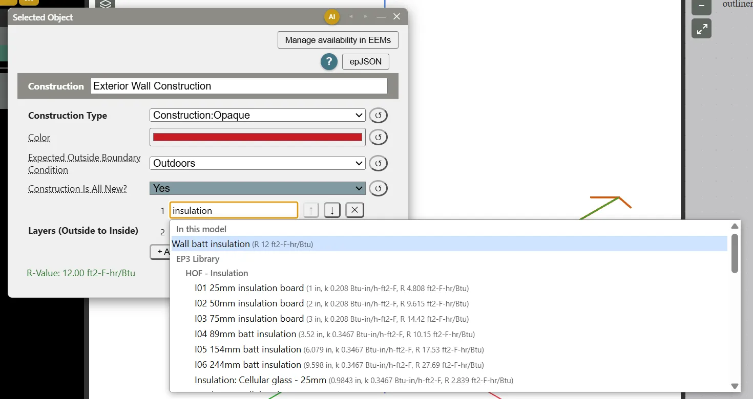
Each layer row has a searchable picker with three sources:
- In this model lists the model’s materials.
- EP3 Library lists the materials that ship with EP3, the ASHRAE 2005 Handbook of Fundamentals material data set, under headers by group: HOF - Insulation, HOF - Masonry / Concrete, HOF - Metal, HOF - Wood, HOF - Finish / Board, HOF - Roofing and HOF - Air layer. The materials inside the
.ep3files of your Library Locations follow, under headers for the location, folder and file they come from. Picking a library material copies it into the model’s Global values; picking it again reuses that copy. A model material of the same name with other values keeps its name, and the new copy gets a number added: “name 2”. - New material… creates a material named New Material in Global, sets it as the layer, and opens it so you can fill in its values.
Each row shows the material’s thickness, conductivity (k) and resistance (R), in your units. A search matches the name, the values shown or a header, and keeps the headers above a match. Picking a library material changes only the layer, in the active EEM; the material itself is in Global, so every EEM sees it.
You can also create materials in the main object dialog, under Materials and Window Properties: select a material type in Column 1 and click Add Object. Most materials arrive with a construction library (§8), which brings each construction’s materials with it; you can also paste their EnergyPlus text into the Import dialog’s Pasted text source.
To keep materials for other models, save the model that holds them as an .ep3 file in a Library Location; its materials then appear in the picker under that Library Location.
3.2 Quick adds: No-Mass and Simple Glazing
Two buttons beside + Add add a layer in one step. Each is one undo step and works in the active EEM.
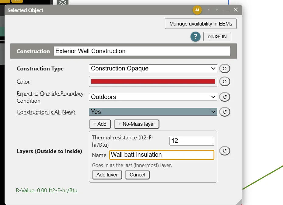
- + No-Mass layer (opaque constructions) asks for a Thermal resistance in your units, at least 0.001 m²·K/W, and a Name, which follows the resistance (
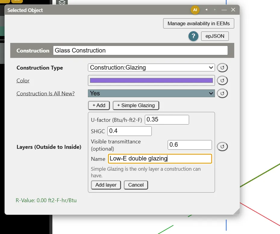
NoMass R-0.5, for example) until you type another. Add layer creates aMaterial:NoMassin Global and adds it as the last (innermost) layer. Adding the same name and resistance again reuses the material. - + Simple Glazing (glazing constructions) asks for a U-factor, an SHGC (above 0 and below 1), an optional Visible transmittance and a Name. EnergyPlus requires a
WindowMaterial:SimpleGlazingSystemto be a construction’s only layer, so when the construction already has layers, the form says they will be replaced and the button reads Replace layers instead of Add layer.
4. Opaque construction performance
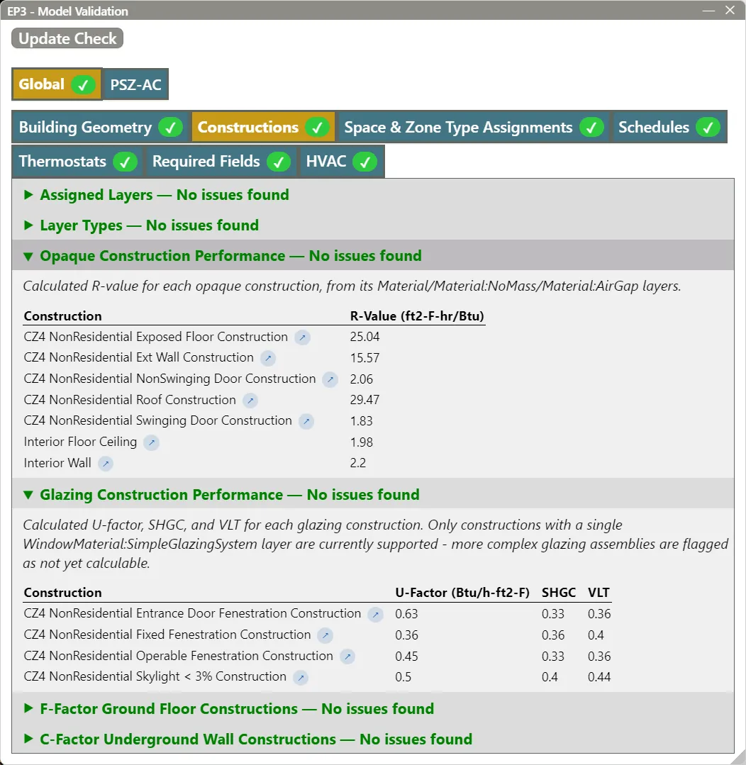
Model Validation (Validate in the top toolbar) calculates the R-value of every opaque construction and lists them on its Constructions tab, under Opaque Construction Performance. The calculation sums each layer’s resistance: thickness ÷ conductivity for a Material, and the entered resistance for a Material:NoMass or Material:AirGap. It excludes air films. A construction with any other layer type is reported as “performance could not be calculated.” The same R-value appears beside each construction in the Constructions panel.
Worked example. The CZ4 NonResidential exterior wall from the Model Wizard’s library has two layers:
| Layer | Type | Values | Resistance |
|---|---|---|---|
| Outside layer: F08 Metal surface | Material |
Thickness 0.0008 m, Conductivity 45.28 W/m·K | 0.0008 ÷ 45.28 = 0.00002 m²·K/W |
| Layer 2: CZ4 NonResidential Ext Wall Construction Insulation | Material:NoMass |
Thermal Resistance entered directly | 2.742 m²·K/W |
Total R-value = 0.00002 + 2.742 = 2.742 m²·K/W. In IP units (1 m²·K/W = 5.678 ft²·°F·h/Btu), 2.742 × 5.678 = 15.57 ft²·°F·h/Btu, the value in the Constructions panel and the validation table.
For a stack where every layer counts, take wood siding (a Material, 0.019 m thick at 0.109 W/m·K: 0.019 ÷ 0.109 = 0.174 m²·K/W), R-13 batt insulation (a Material:NoMass: 13 ÷ 5.678 = 2.290 m²·K/W), and gypsum board (a Material, 0.0127 m at 0.160 W/m·K: 0.079 m²·K/W). The total is 0.174 + 2.290 + 0.079 = 2.543 m²·K/W, or 2.543 × 5.678 = R-14.4 in IP units.
5. Glazing constructions
A Construction:Glazing construction is drawn semi-transparent in the 3D view, and its layer list offers glazing materials.
5.1 WindowMaterial:SimpleGlazingSystem
The simple glazing model takes the rated performance directly, the three values an NFRC label reports:
- U-Factor — the whole-window U-factor, including film coefficients.
- Solar Heat Gain Coefficient — SHGC at normal incidence.
- Visible Transmittance — VT at normal incidence; optional.
The Input Output Reference gives the field definitions and ranges. A simple glazing system is normally the construction’s only layer. Enter the values in the units EP3 is displaying (an NFRC label gives U-factor in Btu/h·ft²·°F); EP3 stores them in SI.
Model Validation’s Glazing Construction Performance table lists each glazing construction’s U-factor, SHGC, and VLT. It evaluates constructions with a single WindowMaterial:SimpleGlazingSystem layer; a more complex stack is reported as not yet calculable.
5.2 Construction:ComplexFenestrationState and Construction:WindowDataFile
For fenestration the simple model cannot represent, such as a shading-integrated glazing unit described by a bidirectional scattering distribution function (BSDF), Construction:ComplexFenestrationState takes a matrix-based description in place of a layer stack; the Input Output Reference documents its inputs. Construction:WindowDataFile reads the assembly from a Window5 or Window6 data file.
5.3 How a window gets its construction
A window gets its construction the way any surface does, by painting (or choosing a construction in its Construction Name list, which does the same), or from where it was placed: the Glass Construction chosen in Add Windows By Exposure, or the construction of its OpeningType. Windows, Shading, and Daylighting covers windows and OpeningType. A window’s OpeningType can differ by EEM, so its construction can too.
A see-through construction (Construction:Glazing, Construction:WindowDataFile, Construction:ComplexFenestrationState) is a window’s, or a glazed face’s. A collection’s Construction list and the Default Constructions slots other than Glass offer only opaque constructions, and EP3 refuses a see-through one on a collection or a floor face. Painting one on a wall or roof face glazes it: the surface keeps its collection’s construction, and EP3 writes the glazing as windows set 25 mm in from the face’s edges (Creating Building Geometry).
6. Ground-contact constructions: F-factor and C-factor
Construction:FfactorGroundFloor and Construction:CfactorUndergroundWall replace a layer stack with EnergyPlus’s simplified ground-coupling methods.
Construction:FfactorGroundFloor: F-Factor (without film coefficients or soil resistance), Area, and PerimeterExposed.Construction:CfactorUndergroundWall: C-Factor (also without films or soil) and Height.
Area and PerimeterExposed are not entered: EP3 calculates them from the geometry painted with the construction and writes them per surface at export.
6.1 The exposed perimeter
PerimeterExposed depends on which slab edges border the outdoors, as opposed to another conditioned space. An F-factor construction’s dialog shows the area and exposed perimeter of the faces painted with it, and four buttons that act on the edges selected in the 3D view:
- Automatically Assign — clears every manual setting on these faces’ edges, so the automatic rule decides: an edge on the slab’s outer boundary is exposed perimeter.
- Add Perimeter — marks the selected edges as exposed perimeter.
- Remove Perimeter — marks the selected edges as not exposed.
- Reset to Auto — returns the selected edges to the automatic rule.
While an F-factor construction is selected, the exposed-perimeter edges are drawn in red in the 3D view, so you can check them against the slab-edge conditions.
Model Validation’s F-Factor Ground Floor Constructions table lists each F-factor construction and compares its assigned perimeter with the perimeter calculated from the geometry, flagging a difference over 10%. The warning is advisory: it points to perimeter edges that may be missing or extra, and it does not stop a simulation. C-Factor Underground Wall Constructions lists each C-factor construction with its height.
6.2 The boundary condition
EnergyPlus requires the GroundFCfactorMethod boundary for surfaces using either method. EP3 exports every surface painted with an F-factor or C-factor construction with that boundary.
7. Construction:AirBoundary
Construction:AirBoundary models a boundary between two zones with no thermal resistance: the surface exists for zoning and geometry, but heat passes through it freely. Its Air Exchange Method (None or SimpleMixing) can add air mixing across the boundary at Simple Mixing Air Changes per Hour (based on the smaller zone’s volume), on an optional Simple Mixing Schedule Name.
8. Construction libraries
To reuse a set of constructions in other models, save a model that holds them as an .ep3 file in one of your Library Locations. Every .ep3 file there is a template: the Model Wizard’s Constructions tab and the Import dialog’s Library templates tab list the file with its constructions, each of which brings the materials it uses. An EEM of the file that changes one of those constructions or materials is offered in a column beside them (The Model Wizard). Constructions painted onto surfaces in an EEM do not travel with a template; they come only with an import of the whole .ep3 file. The file offers its other contents on the other tabs too, so keep in it only what the template should offer.
Simulate before you save a library. Run a simulation with the constructions in a model before saving it as a template. A construction that exports and simulates without error is known to work; one saved without that check can carry a problem (a mismatched layer, a missing required field) that appears only when someone uses the library in another project.
8.1 Names that Default Constructions recognize
Model Settings > Default Constructions sets a default construction per surface category. When a slot is empty, or its construction was deleted, EP3 fills it with the first construction whose name contains the words below and whose type and expected boundary suit the slot:
| Slot | Name contains | Construction must be |
|---|---|---|
| Exterior Walls | “ext” and “wall” | opaque, Outdoors |
| Interior Walls | “int” and “wall” | opaque, Surface |
| Roof | “roof” | opaque, Outdoors |
| Glazing | “fixed”, else “glazing”, “fenestration”, “glass”, or “win”, passing over an entrance door’s or a skylight’s glazing while another one matches | a fenestration type |
| Interior Floor & Ceiling | “int” and “floor”, or “int” and “ceil” | opaque, Surface |
| Underground Floor | “underground floor”, “slab”, “f factor”, or “f-factor” | opaque, Ground or GroundFCfactorMethod |
| Underground Walls | “underground wall”, “below”, “grade”, and “wall”, or “c factor” | opaque, Ground or GroundFCfactorMethod |
| Exposed Floor | “exposed” and “floor” | opaque, Outdoors |
| Doors | none: choose it yourself | opaque |
Names are matched without regard to case. EP3’s construction libraries follow this convention (“CZ4 NonResidential Ext Wall Construction,” “CZ4 NonResidential Roof Construction,” “CZ4 NonResidential Below-Grade Wall Construction”), so their constructions fill the slots on import. Naming your own constructions the same way (<something> Ext Wall Construction, <something> Roof Construction, and so on) gives your libraries the same behavior.
9. Populate Constructions
Populate Constructions, an icon button in the header of the Constructions panel, fills the model’s constructions from the constructions of another .ep3 file. It saves creating materials and picking layers one at a time, and it pairs constructions by surface slot or by your choice, so an upgraded set works even when its names differ from the model’s. It changes the contents of the constructions only. Their names, their assignments (paint, Spaces, Space Types, collections and Opening Types), the Default Constructions and the surfaces stay as they are, and nothing is removed.
Two common uses:
- Fill blank constructions. A model started without the Model Wizard has default constructions with no layers. Choose a library file with a complete set, and each blank construction takes the layers of the matching construction.
- Load an upgraded envelope into an EEM. Choose the EEM as the target and a file with the upgraded walls, roofs and windows. The model’s constructions change in that EEM only, and EEMs built on it inherit the change.
9.1 Choosing the source and the target
- Source is any
.ep3file: pick one from the library tree (EP3 Library and your Library Locations; only files with constructions are listed) or click Browse…. The tree closes once a file is chosen; Choose from library opens it again, and Rescan re-reads the library folders. - Target EEM is any EEM of the model, Global included. It starts as the active EEM. EEMs that use branching and the HVAC and service hot water system EEMs are listed but cannot be chosen, with the reason shown.
- Read from is the EEM of the source file that supplies the values written into the target. It starts as Global.
Changing the source, the target or Read from starts the table again from its pre-filled choices.
9.2 Mapping constructions
The Constructions tab, whose name shows the number of mapped rows, has one row for each construction in the model, in three columns: Target Construction (the name, with its R-value or U-factor now in the target EEM), Source Construction Type, and Source construction, the construction to take values from, with its R-value or U-factor shown under it.
- EP3 pre-fills a row when the construction is the model’s default for a surface slot (Exterior Walls, Roofs and so on) and the source’s construction for that slot has the same type. A glazing construction is only ever pre-filled with a glazing construction.
- When no slot matches, EP3 looks for a source construction of the same type with a matching name: the same name, a name that differs only by leading words such as a climate zone, or a very similar name. It fills the row only when one candidate is clearly the best, and the row says “Matched by name” so you can check it. Climate zones and the words Residential and NonResidential do not count toward a match.
- A row stays at (leave as is) when the source’s construction for its slot is of another type, with the note “Not filled: <name>” naming that construction, or when the source’s construction has the same values, with the note “Already matches (<name>)”. A row at (leave as is) is not changed. Built-in constructions are listed but cannot be mapped.
- The source list of a row holds the source’s constructions of the type chosen in the Source Construction Type column. One source construction can fill any number of rows, for example residential and nonresidential walls both taking the upgraded wall.
- Choosing another Source Construction Type is a deliberate change of the construction’s type, for example from Opaque to F-Factor Ground Floor. It clears the Source construction until you choose one of the new type, and a row with a changed type is tinted and says “Type changes”. Returning to the original type brings the pre-fill back.
A name filter narrows the rows.
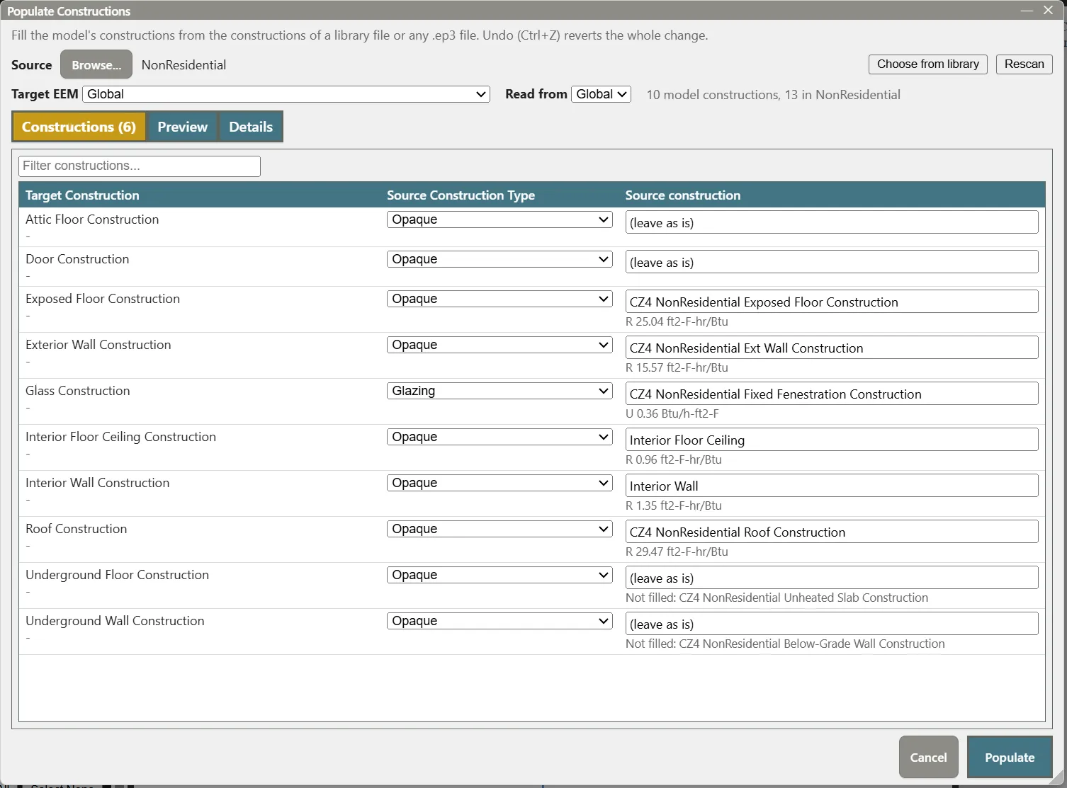
For each mapped row, Populate writes every field of the source construction into the target EEM except its name and its color. Expected Outside Boundary Condition and Construction Is All New? are copied when the target EEM is Global, since they exist only there; for another target EEM they keep their values. That includes its layers in the source’s order, its type and the fields of that type, such as the C-factor and height. Materials the model lacks come into Global. A material of the same name is reused when its values match; otherwise a copy with a number added, such as “name 2”, comes in.
9.3 Source EEMs
When the source file has EEMs that change a mapped construction or one of its materials, EEMs from the source file appears under the table; without such EEMs, nothing is shown. Each selected EEM is imported into your model. If you already have an EEM with the same name, construction changes from the source file appear in your existing EEM. Each EEM has a check box, on by default, with Check all and Uncheck all. Hover over one to see which constructions it changes and what it builds on. A checked EEM comes into the model as an EEM built on the target EEM, with the source’s values for it. If the model has an EEM of the same name, anywhere in its tree, the values merge into it and bring only the changes the source EEM makes. An HVAC or SWH system EEM or a branching EEM of that name takes no merge, and the new EEM takes the name with a number added. Otherwise the new EEM takes the source’s name and description; the source EEM’s weather file and Available for Simulation setting do not come along.
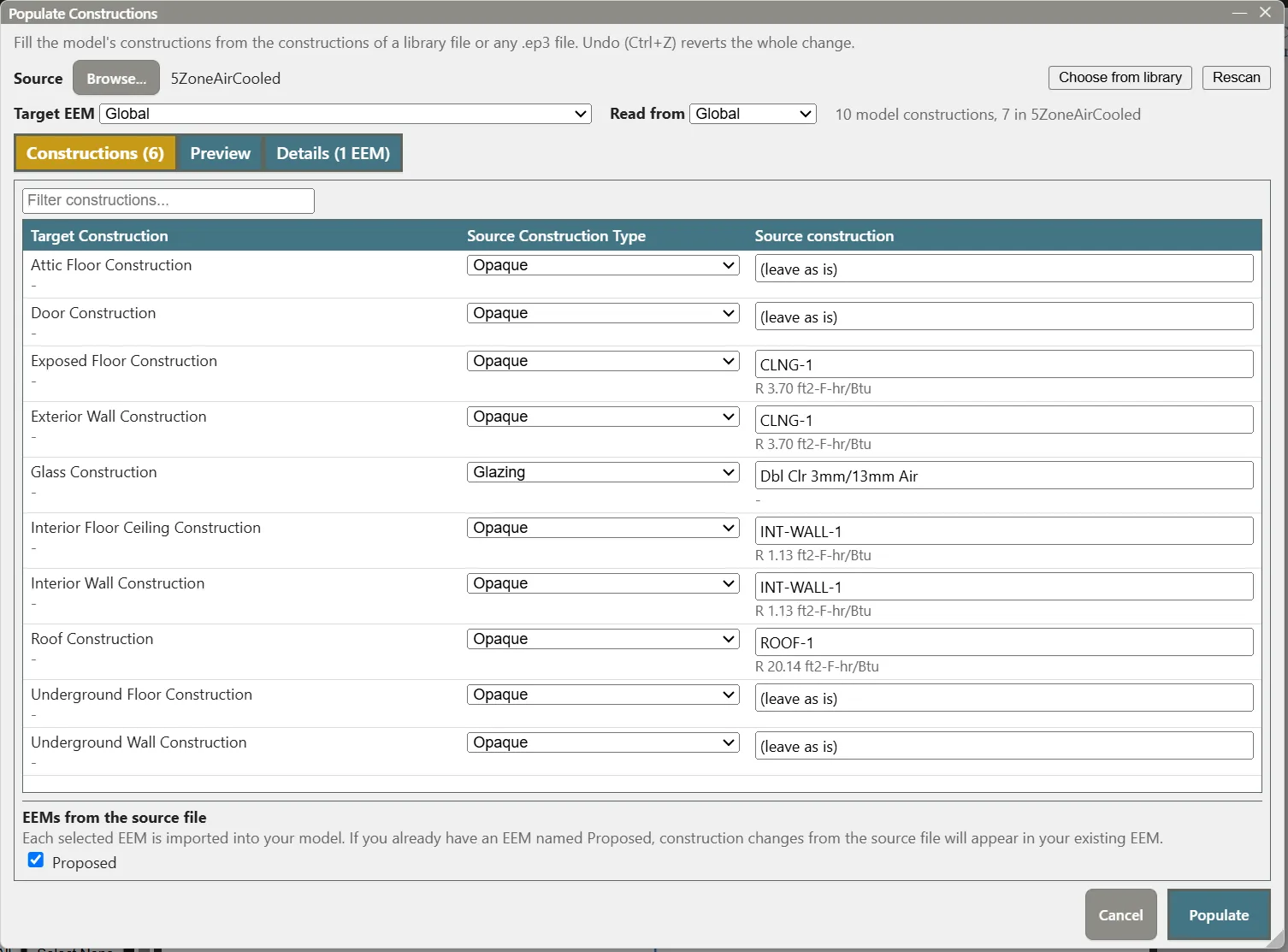
An EEM left unchecked while one built on it stays checked shows Flatten and Re-parent, with the same meanings as in the template pickers (The Model Wizard). Re-parent is the default.
9.4 Preview and Details
Before you populate, two tabs show the result:
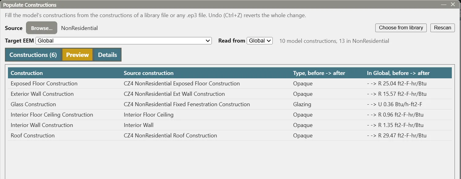
- Preview lists, for each mapped row, the type and the R-value, U-factor, F-factor or C-factor in the target EEM now and after Populate. A type change is shown in amber. Warnings come first: a type change can move a Default Constructions slot to another construction (a wall made glazing no longer fits Exterior Walls), and anything that could not be brought is listed.
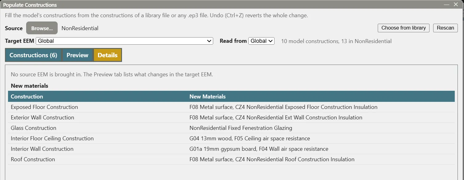
- Details lists each EEM that will come in, either as a new EEM on its parent or merged into an existing one, with every value it changes by object (constructions and materials), the model’s value before and after, and a New materials table that lists, for each construction, the materials that come into the model, with a number added to a name the model already uses for a different material. When an EEM changes a material that other constructions also use, those constructions are listed as affected, because they change with it in that EEM.
9.5 Populating
Populate is available once at least one row is mapped. It runs as one undo step and is recorded in the import history as Populate Constructions. The dialog then shows the result, such as “Populate Constructions. 3 constructions populated. 4 materials created, 1 reused. 1 EEM created. Undo (Ctrl+Z) reverts it.”, followed by anything that could not be brought and Open the report in Import Details (Importing EnergyPlus Files).
Some values are not carried over. A source EEM with several parents comes in on its nearest checked ancestor only, and values it reads from its other parents come only through Flatten. A source construction with no layers leaves the layers the model construction already inherits in that EEM.
This handbook is also built into EP3 (Help), where its EnergyPlus links open the EnergyPlus Reference. Technical specifications · Book a demo