Start from an architect’s DXF (Drawing Exchange Format) drawings and finish with a nine-storey apartment building ready to simulate: one Space per apartment, Space Types and Fan Coil equipment on every zone, and windows sized and placed from the elevations. Two floor plans make all nine storeys and two elevations place the windows, so nothing is traced by hand.
What you need
- EP3 3.0.
- The four drawings used here. Save them to one project folder. They are large files (16 to 20 MB each), so allow time for the download and a few seconds for each import:
- ground-floor.dxf (about 20 MB)
- typical-floorplan.dxf (about 16 MB)
- North.dxf (about 16 MB)
- South.dxf (about 16 MB)
- An EnergyPlus weather file (.epw). The screenshots use
USA_VA_Sterling-Washington.Dulles.Intl.AP.724030_TMY3.epw(Washington Dulles, climate zone 4A), from https://energyplus.net/weather. Keep its .stat and .ddy files beside it. The constructions chosen below are for climate zone 4. - About 75 minutes.
- The screenshots use SI units (m, °C).
The drawings keep their CAD layers (walls, doors and windows, furniture, text and so on, with Spanish names). Both tools used here, Floor from Drawing and Windows from Elevations, read only the lines on the layers you leave on.
Set up the model with the Model Wizard
The Model Wizard opens when EP3 starts without a file, and each time you choose File > New.
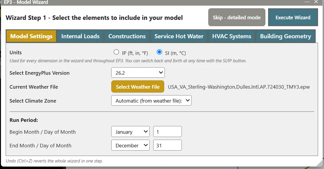
- On Model Settings, choose SI (m, °C) for Units.
- Click Select Weather File and choose your weather file.
- Leave Select Climate Zone at Automatic (from weather file). It then reads Automatic (from weather file): 4A.
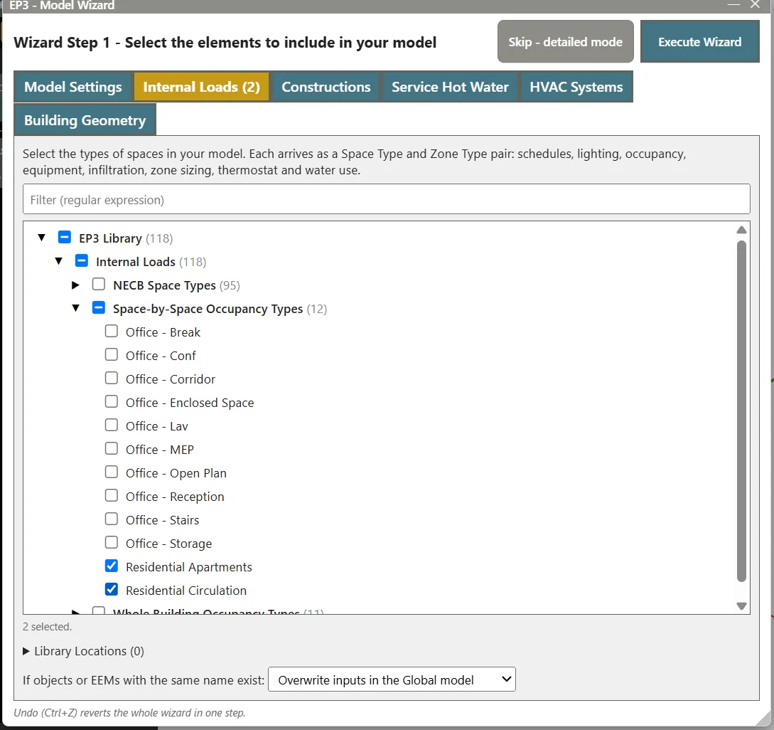
- On Internal Loads, expand EP3 Library > Internal Loads > Space-by-Space Occupancy Types.
- Tick Residential Apartments and Residential Circulation.
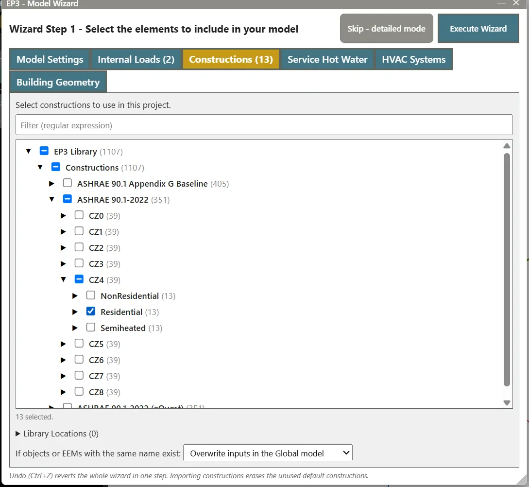
- On Constructions, expand EP3 Library > Constructions > ASHRAE 90.1-2022 > CZ4.
- Tick Residential.
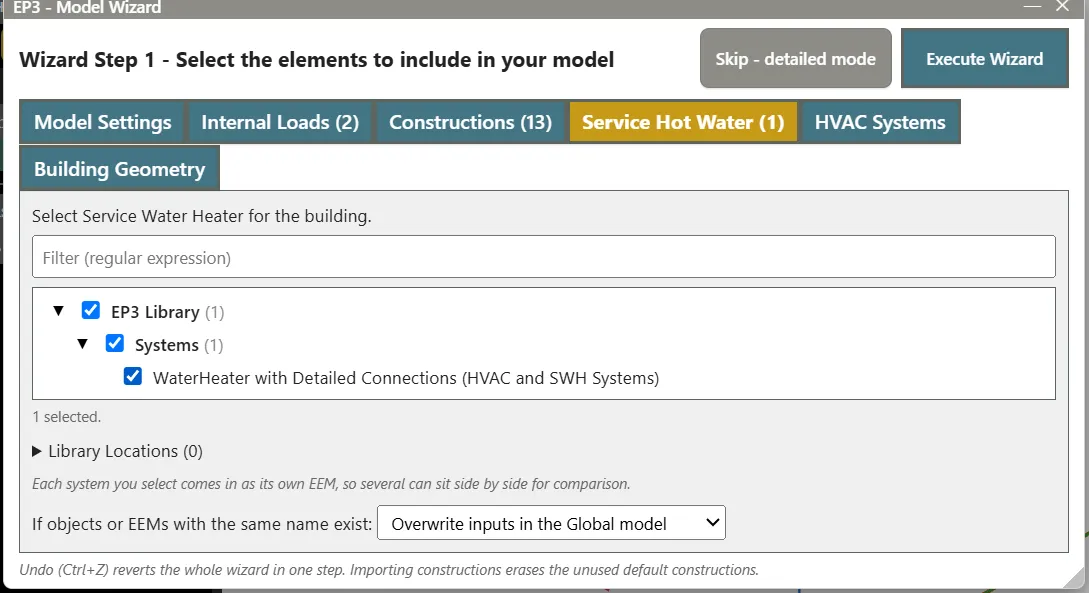
- On Service Hot Water, expand EP3 Library > Systems.
- Tick WaterHeater with Detailed Connections.
- On HVAC Systems, expand EP3 Library > Systems > HVAC and SWH Systems.
- Tick Fan Coil.
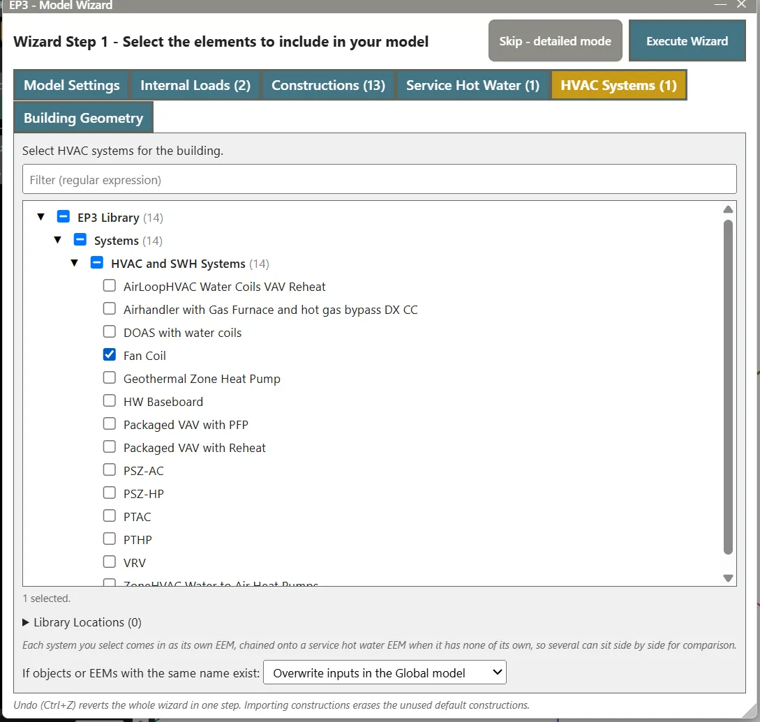
- On Building Geometry, choose I want to draw my own building geometry.
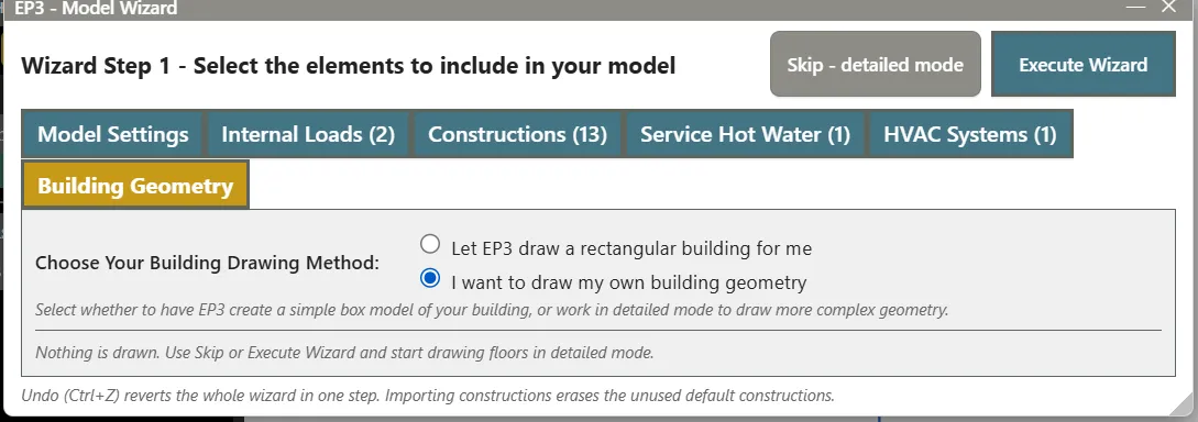
- Click Execute Wizard.
The status bar reads “Templates: 3 file(s), 180 object(s) added, 2 EEM(s).” The Fan Coil system’s plant loops and the service water loop appear in the HVAC Outliner on the right. The button over the 3D view reads Mode Automatic, so EP3 makes the walls, roofs and constructions each time a Floor is finished.
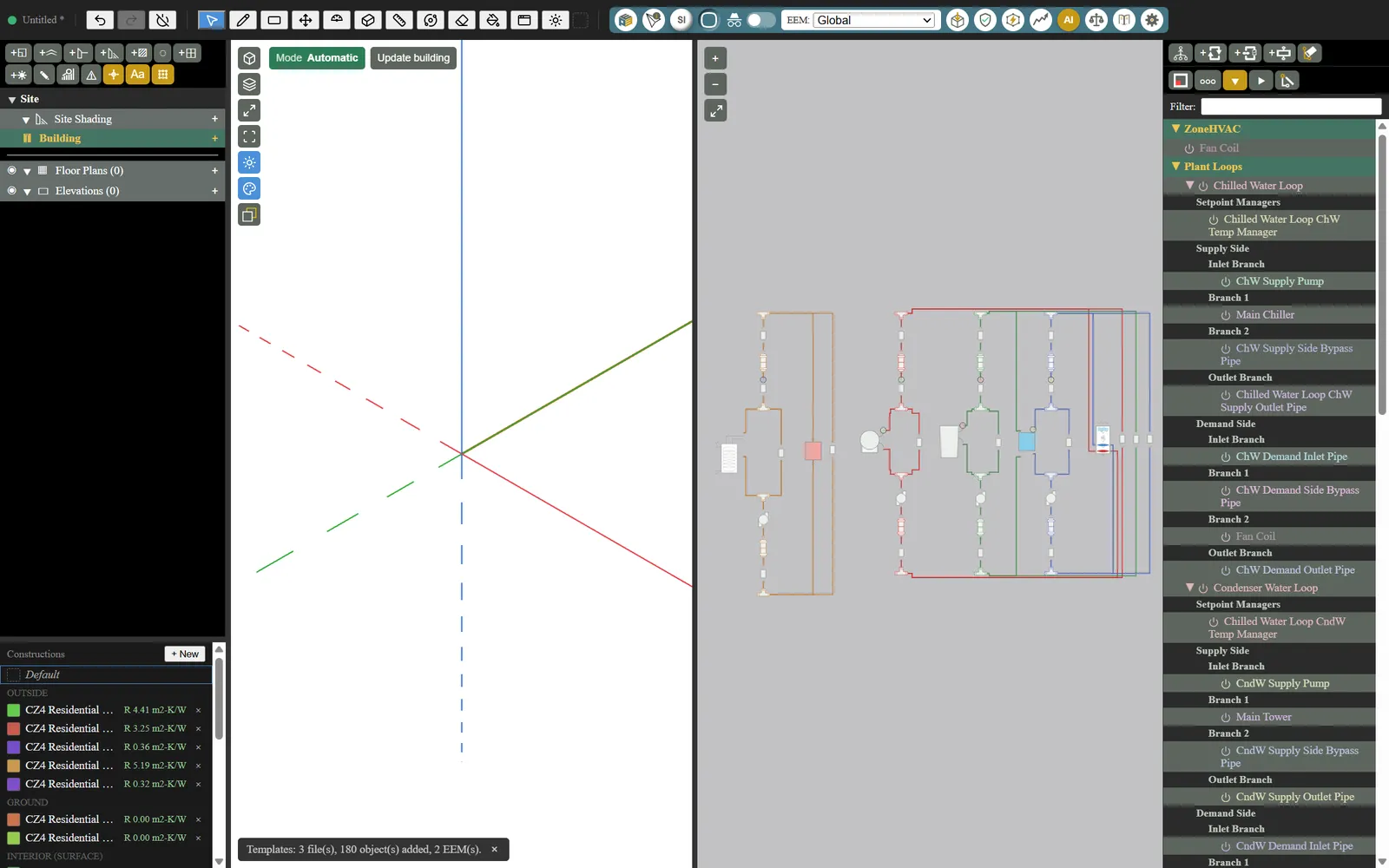
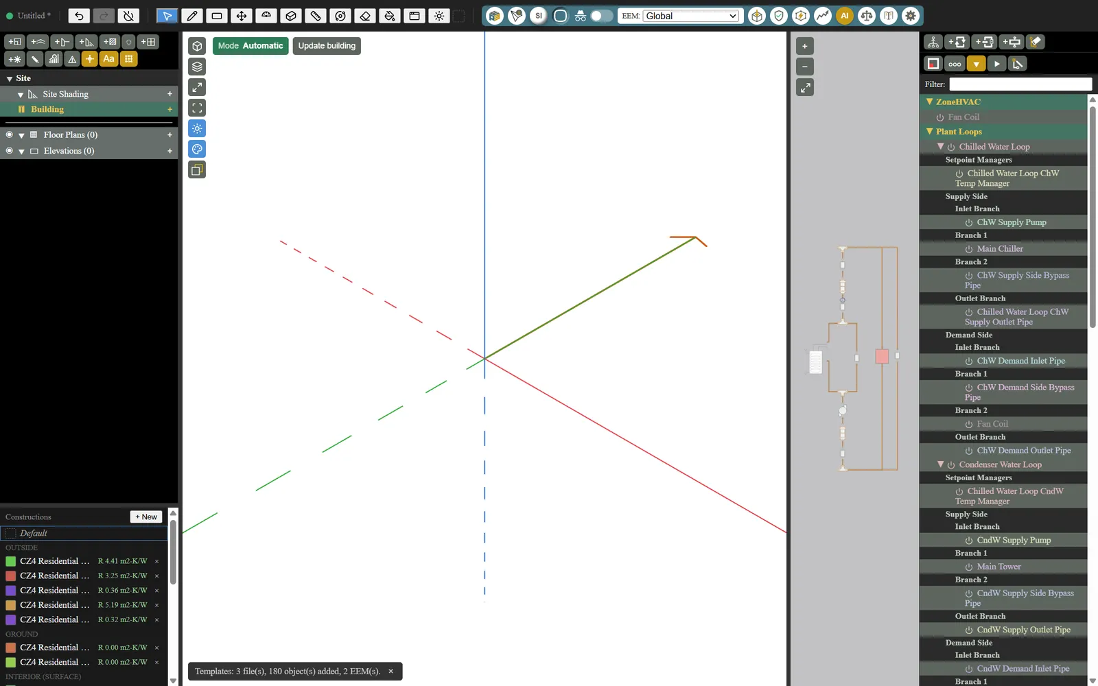
- Drag the divider between the 3D view and the HVAC diagram to the right to give the 3D view more room.
Make the ground floor from its plan
Floor from Drawing reads a DXF floor plan and makes a Floor, with its outline, interior walls and Spaces, in seven steps: Scale and turn, Crop, Layers, Place, Exterior walls, Spaces, and Names and types.
Start the Floor
- In the Building Geometry Outliner’s toolbar, click Add Floor.
- In Choose method, choose Generate from Floorplan.
- Set Ceiling height (meters, floor to floor) to 2.90. The elevations are drawn with 2.90 m storeys, so with Floors of the same height each window from the elevations lands on the right storey.
- Leave Floor multiplier at 1 and Starts at (meters) at 0.
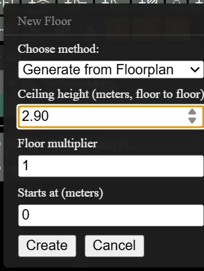
- Click Create.
- Choose ground-floor.dxf.
Scale and turn
The Floor from Drawing panel opens at the right of the view, on Step 1 of 7: Scale and turn. Every layer of the drawing is shown on this step. The line “True size, from the drawing’s own units.” means EP3 has read the drawing’s units, so the plan is already full size. It is also the right way up.
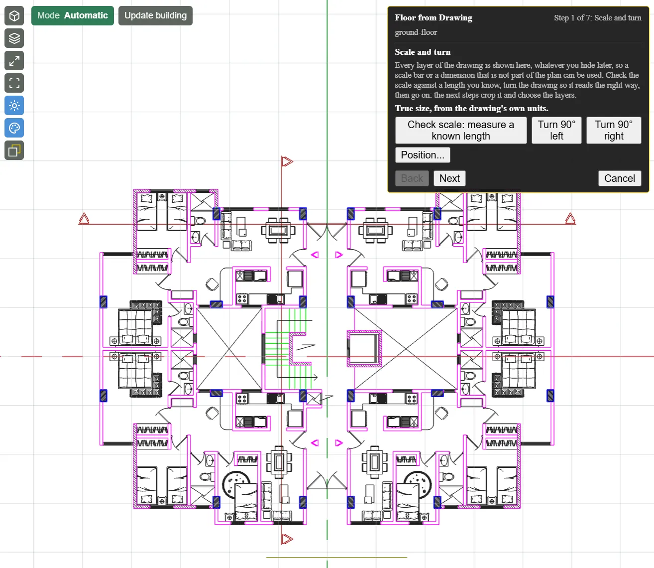
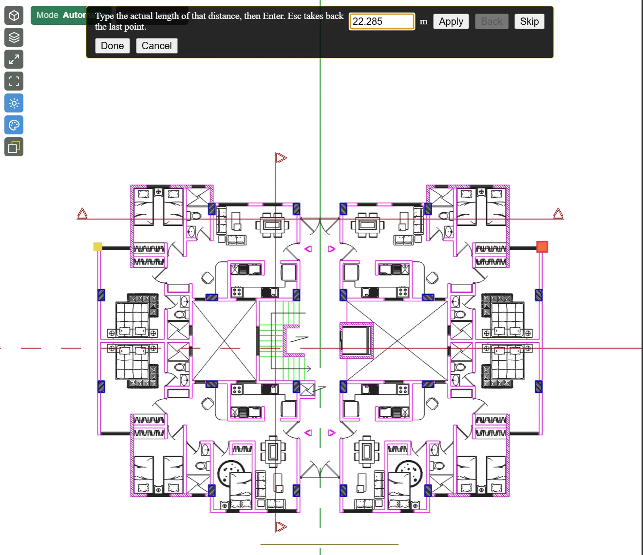
Checking the scale is optional. To check it, click Check scale: measure a known length, then click the two ends of a length you know; the clicks snap to the drawing’s line ends. The bar shows the measured length. If it is wrong, type the true length and press Enter. Cancel in the bar discards the measurement.
- Click Next.
Crop
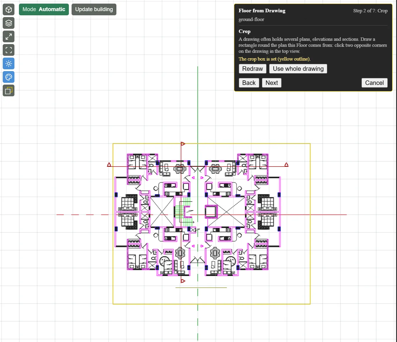
The sheet also holds a title block and other parts below the plan. Crop to the plan itself.
- Click one corner just outside the plan, then the opposite corner. The crop box appears as a yellow outline, and the panel reads “The crop box is set (yellow outline).”
- Click Next.
Layers
EP3 reads each layer’s role from its name and turns the layers on or off to suit. The panel reads “Suggested: 5 layers on, 4 off (names read as Spanish).” The walls (0. MUROS), columns (0. COLUMNAS) and doors and windows (0. PUERTAS Y VENTANAS) stay on. Furniture (0. MUEBLES), text (0. TEXTO), stairs (0. ESCALERAS) and section marks (0. CORTES) are off, so they are not read as walls.
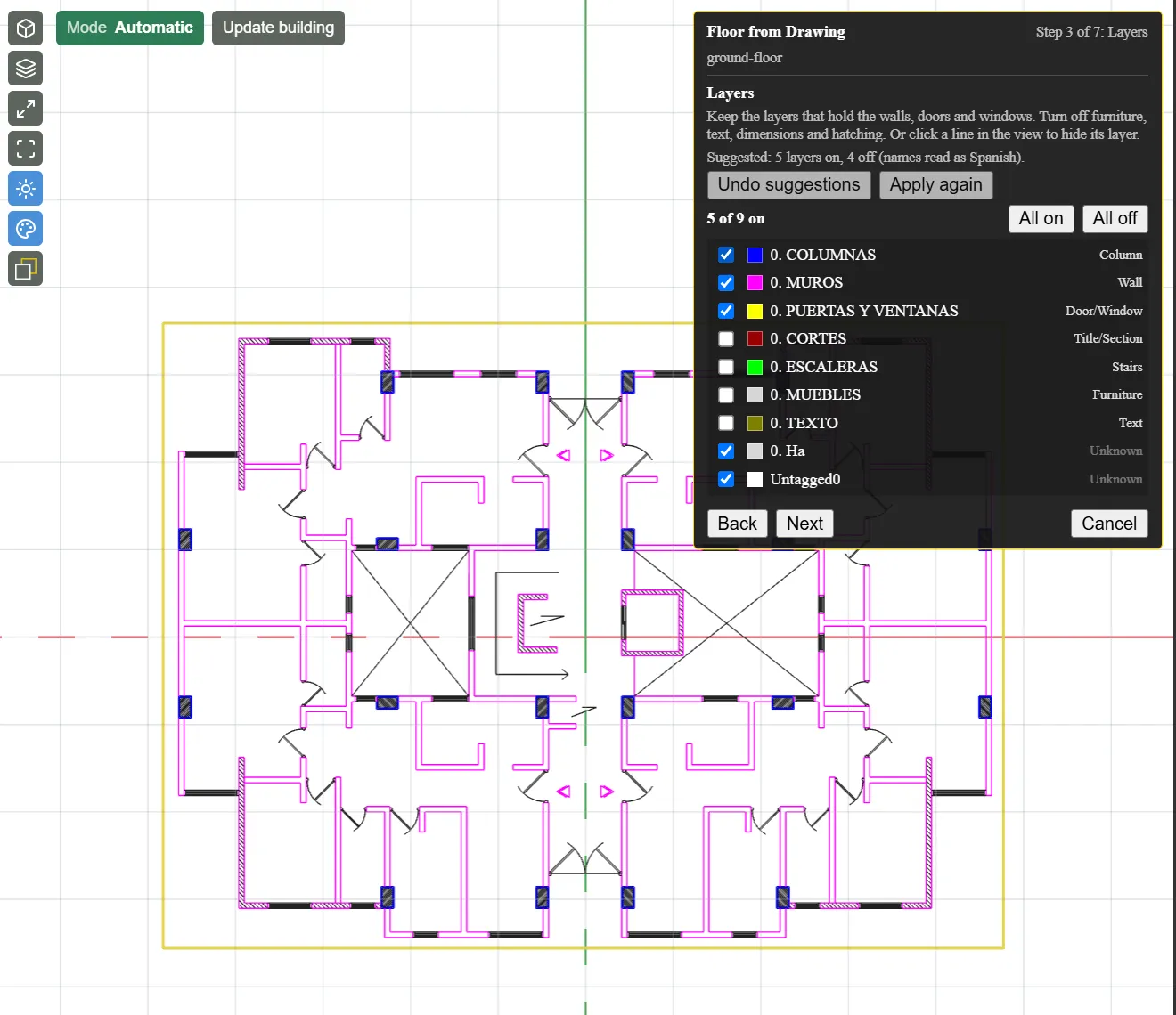
- Leave the suggestion as it is and click Next.
Tip: You can also click a line in the view to hide its layer.
Place
This is the first Floor, so there is no Floor below to line the plan up with. Put the south-west corner of the building at the model origin.
- In Floor name, type
Ground Floor. - Check that Ceiling height shows Specify Ceiling Height and 2.9, Floor multiplier 1, and Starts at (m) 0.
- Click Position…. The bar reads “Position: click a reference point on the drawing.”
- Click the outer corner of the building’s south-west wall on the plan.
- Click the origin. It is labelled Origin when the pointer snaps to it.
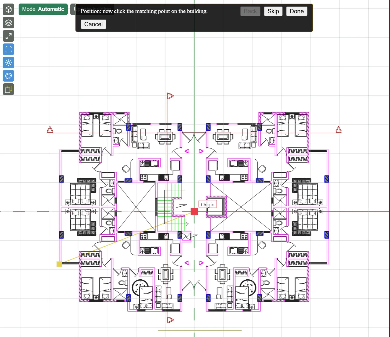
Position… runs only this position step and then returns to the panel, with the plan’s south-west corner at the origin.
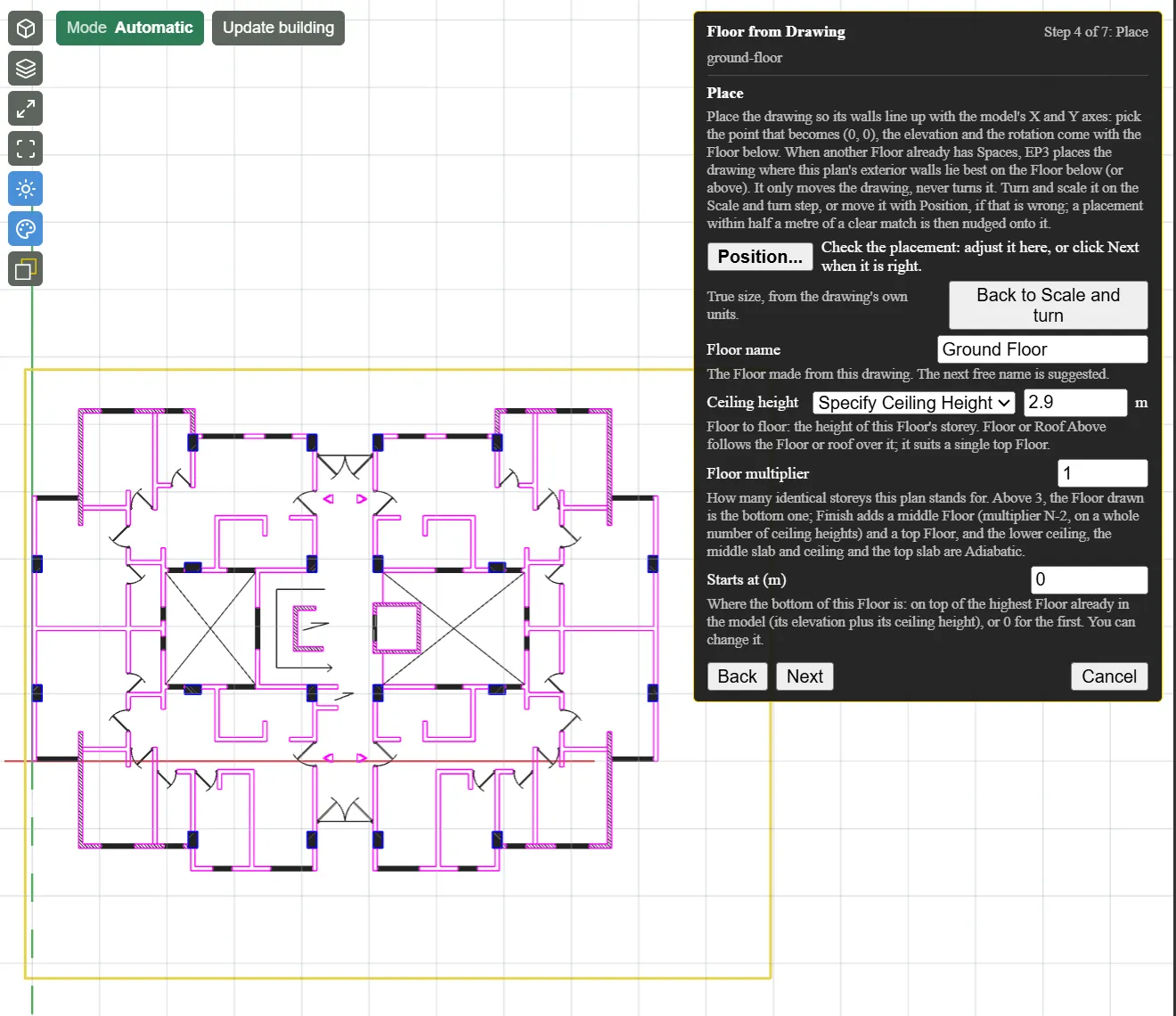
- Click Next.
Exterior walls
EP3 finds the building’s outline and writes it onto the Floor. The status reads Outline closed, so the outline needs no repair. Leave the settings as they are.
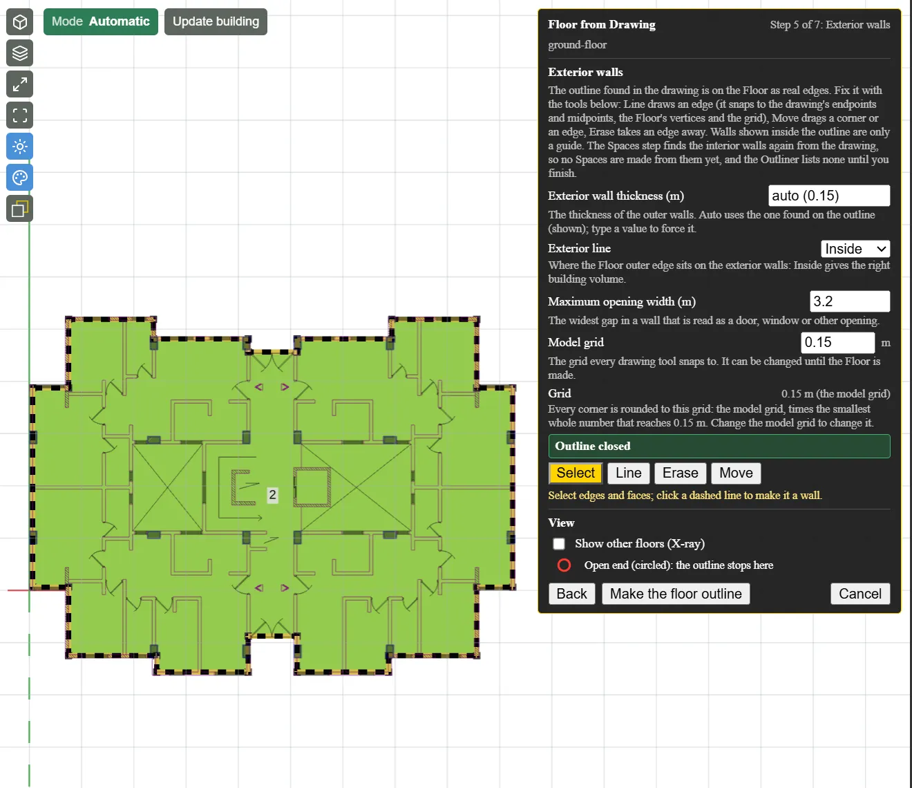
- Click Make the floor outline.
Spaces
EP3 makes the Floor with every interior wall it can identify. The summary reads “14 Spaces, no dangling ends”. The dashed lines are maybe walls: walls the drawing suggests but does not confirm. Click one with Select to make it a wall. Line, Erase, Move and Void edit the walls, and each edit can be undone.
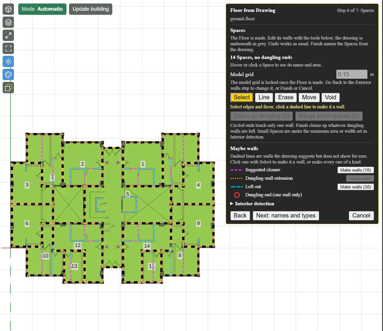
The two light wells, crossed with an X in the drawing, open into the apartments beside them through a window gap, so EP3 counts each as part of the neighbouring Space. Close them off and make them voids.
- Zoom in on the west light well.
- Click Line.
- Draw a line across the window gap at the light well’s north-west corner, from the corner of the wall to the end of the wall on the other side.
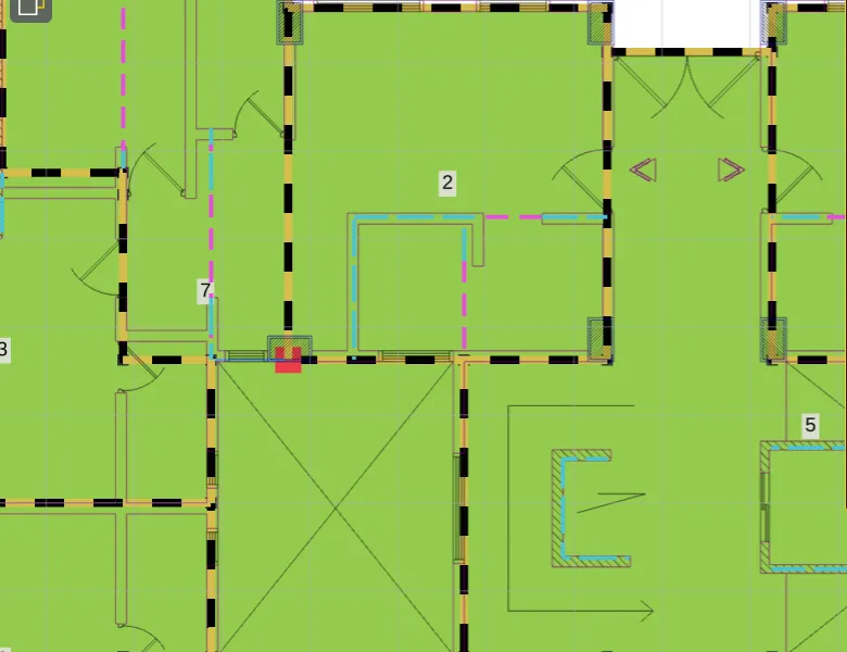
- Close the east light well the same way. Its side facing the corridor and a short piece of its north wall are open, so it takes two lines.
- Click Void.
- Click inside each light well.
- Press Esc.
The summary reads “15 Spaces, 2 voids, no dangling ends”, and each light well is marked void.
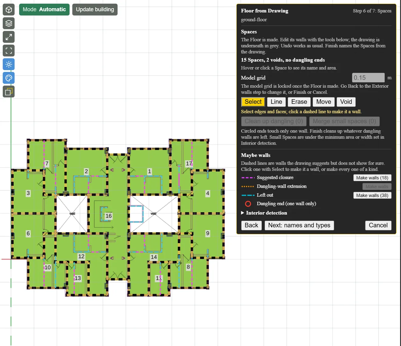
Four apartments are split into rooms. Erase the walls between those rooms so each apartment is one Space. Erasing a wall merges the Spaces on either side.
- Click Erase.
- In each apartment, drag across the walls between its rooms, one row of walls per sweep. Eight sweeps cover the four apartments.
After the sweeps the summary reads “5 Spaces, 2 voids, 10 dangling ends”. The dangling ends, circled, are pieces of wall left touching only one other wall.
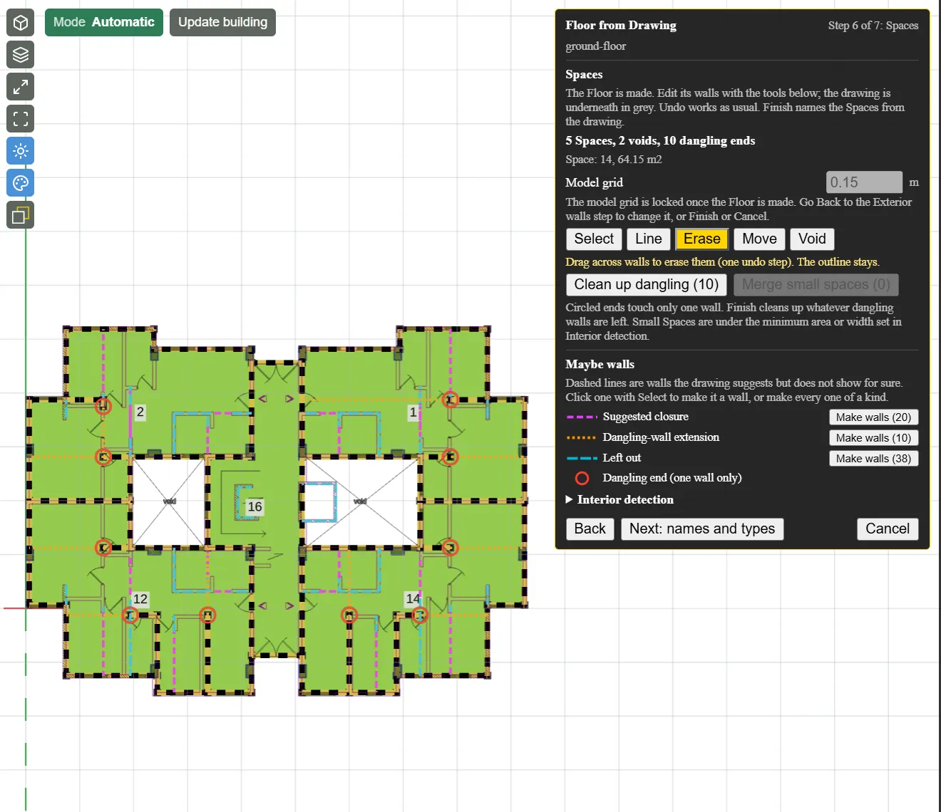
- Click Clean up dangling (10).
- Click Select.
The summary reads “5 Spaces, 2 voids, no dangling ends”: four apartments, and the corridor with the stairs.
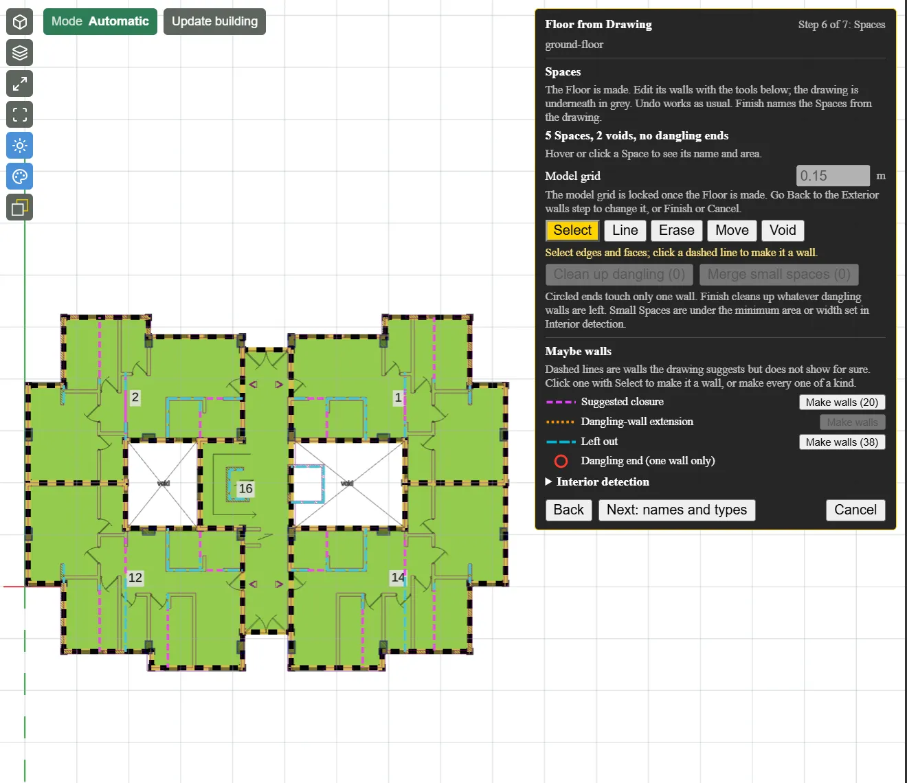
- Click Next: names and types.
Names and types
The table lists the 5 Spaces in reading order. Each row’s number in the No. column is also drawn on its Space in the plan. The drawing has no room labels, so Text in drawing shows “-” in every row. Here the corridor is row 3.
- Tick rows 1, 2, 4 and 5, the apartments.
- In the list above the table, choose Residential Apartments.
- Click Set Space Type.
- In the name box (its placeholder reads “Name, e.g. Apt or Apt #”), type
Apt #.
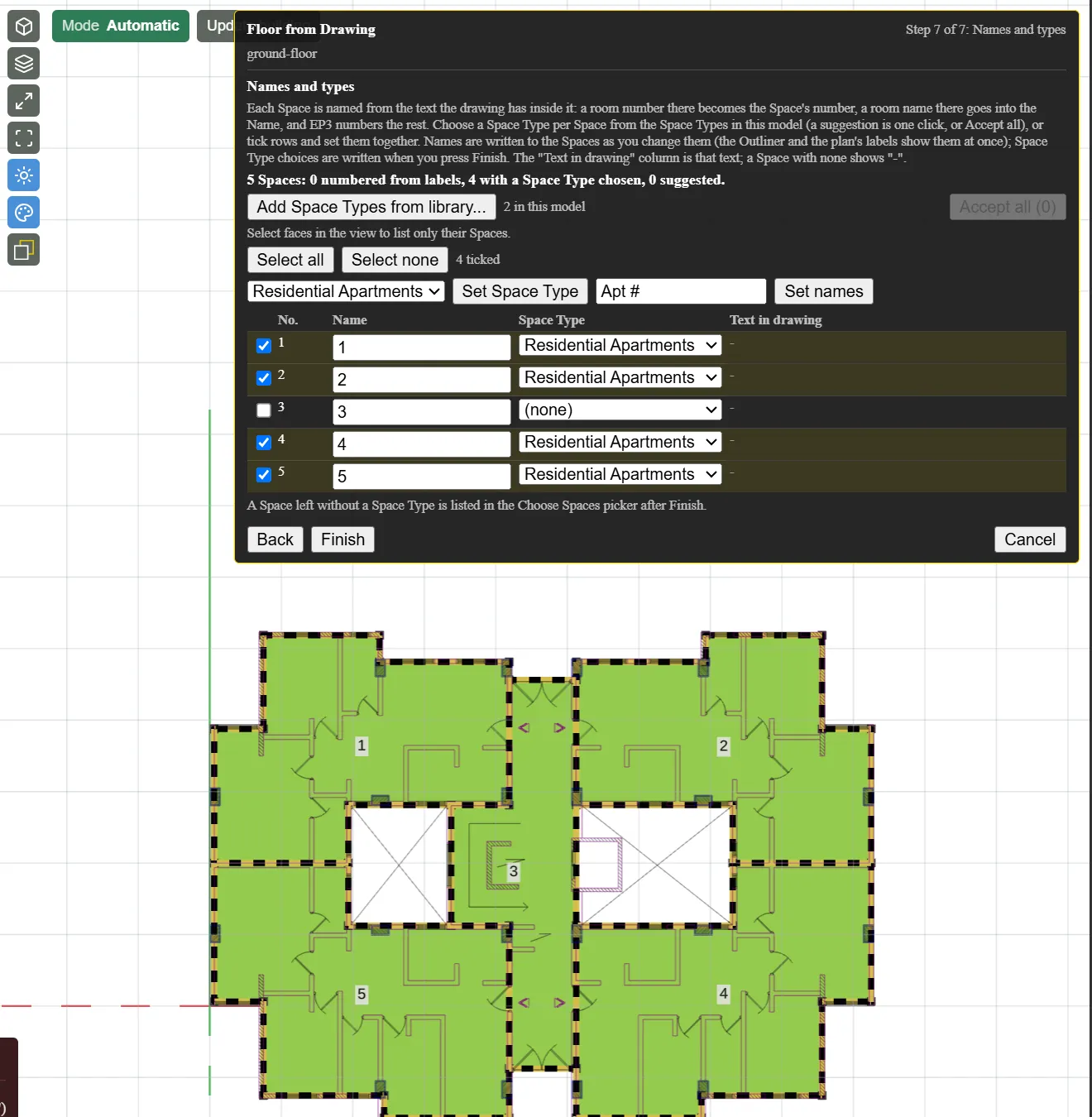
- Click Set names. The # takes each Space’s number: Apt 1, Apt 2, Apt 4 and Apt 5.
- Click Select none.
- Tick row 3.
- Choose Residential Circulation and click Set Space Type.
- In row 3’s Name box, replace 3 with
Corridor and stairs.
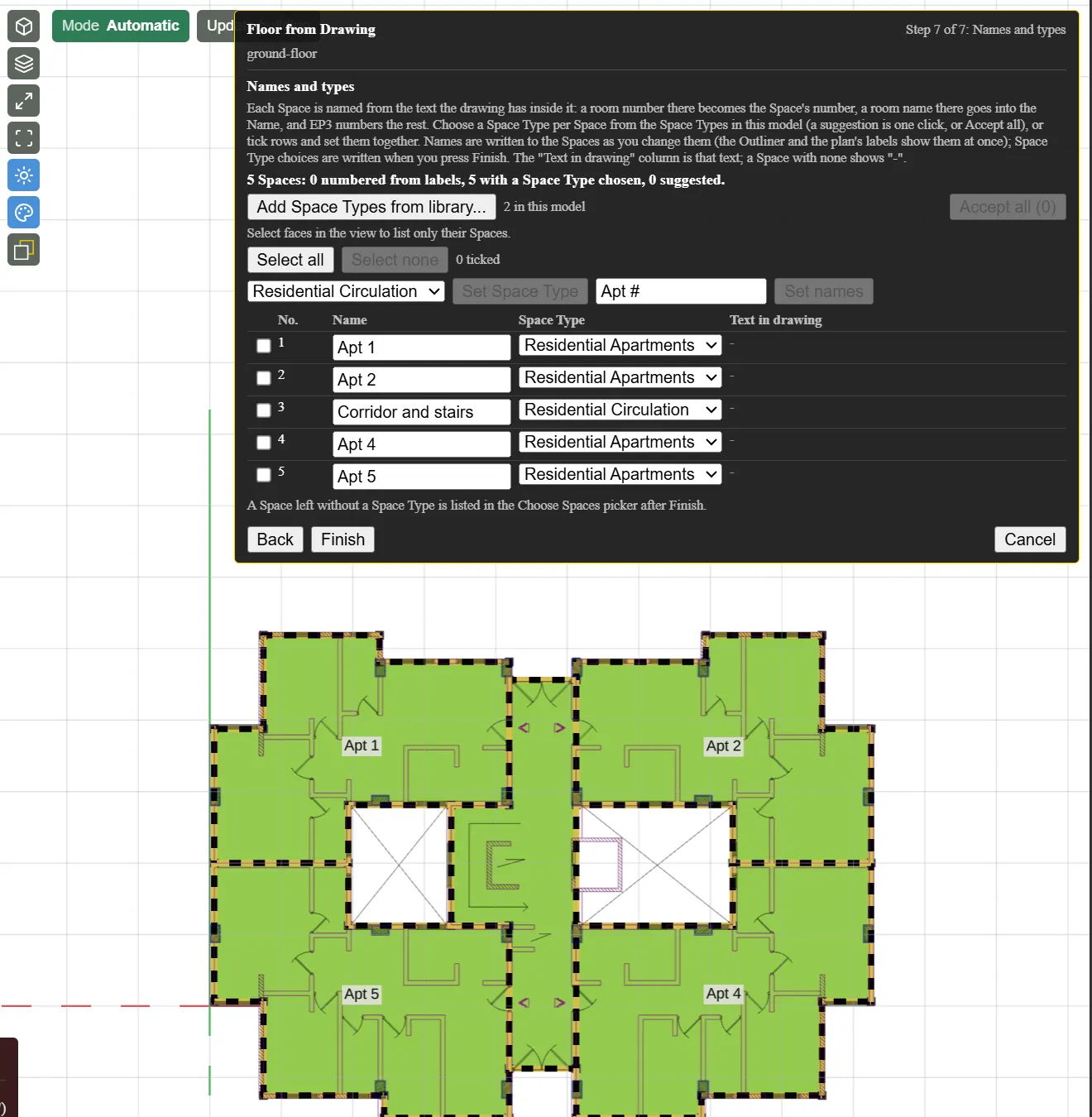
- Click Finish.
EP3 asks “Assigning Space Types switches the model to assign Space Types by selection. Switch?”

- Click Switch.
No would finish with the names only and leave every Space Type unassigned.
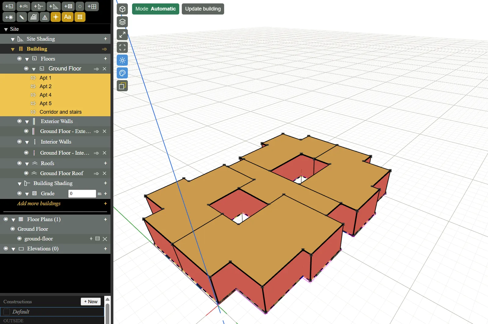
EP3 makes the Ground Floor with its 5 Spaces and, in Automatic mode, its exterior walls, interior walls and roof.
Add eight typical floors from one plan
The typical plan stands for the eight storeys above the ground floor. A Floor multiplier of 8 makes them all from one drawing, so the building has nine storeys.
Start the Floor
- Click Add Floor.
- In Choose method, choose Generate from Floorplan.
- Check that Ceiling height (meters, floor to floor) is 2.9.
- Set Floor multiplier to 8.
The note under the field reads “Makes a bottom, a middle (multiplier 6) and a top Floor. The lower ceiling, the middle slab and ceiling, and the top slab are Adiabatic.”
- Leave Starts at (meters) at 2.9, the top of the Ground Floor.
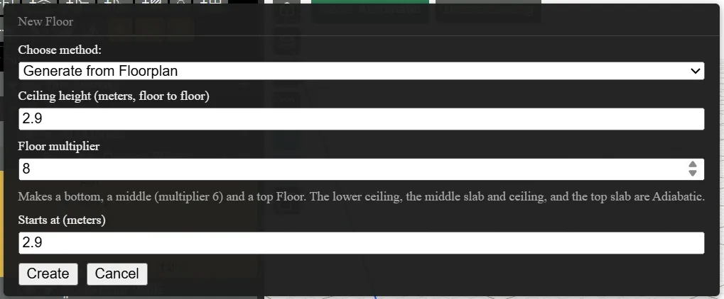
- Click Create.
- Choose typical-floorplan.dxf.
Scale, crop and layers
- On Scale and turn, click Next.
- On Crop, click two opposite corners of a box round the plan, and click Next.
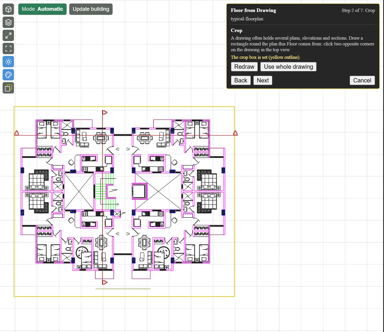
Layers follows the ground floor’s choice by name. The panel reads “Matched the layers of ground-floor: 7 on, 5 off; 4 new names suggested.”
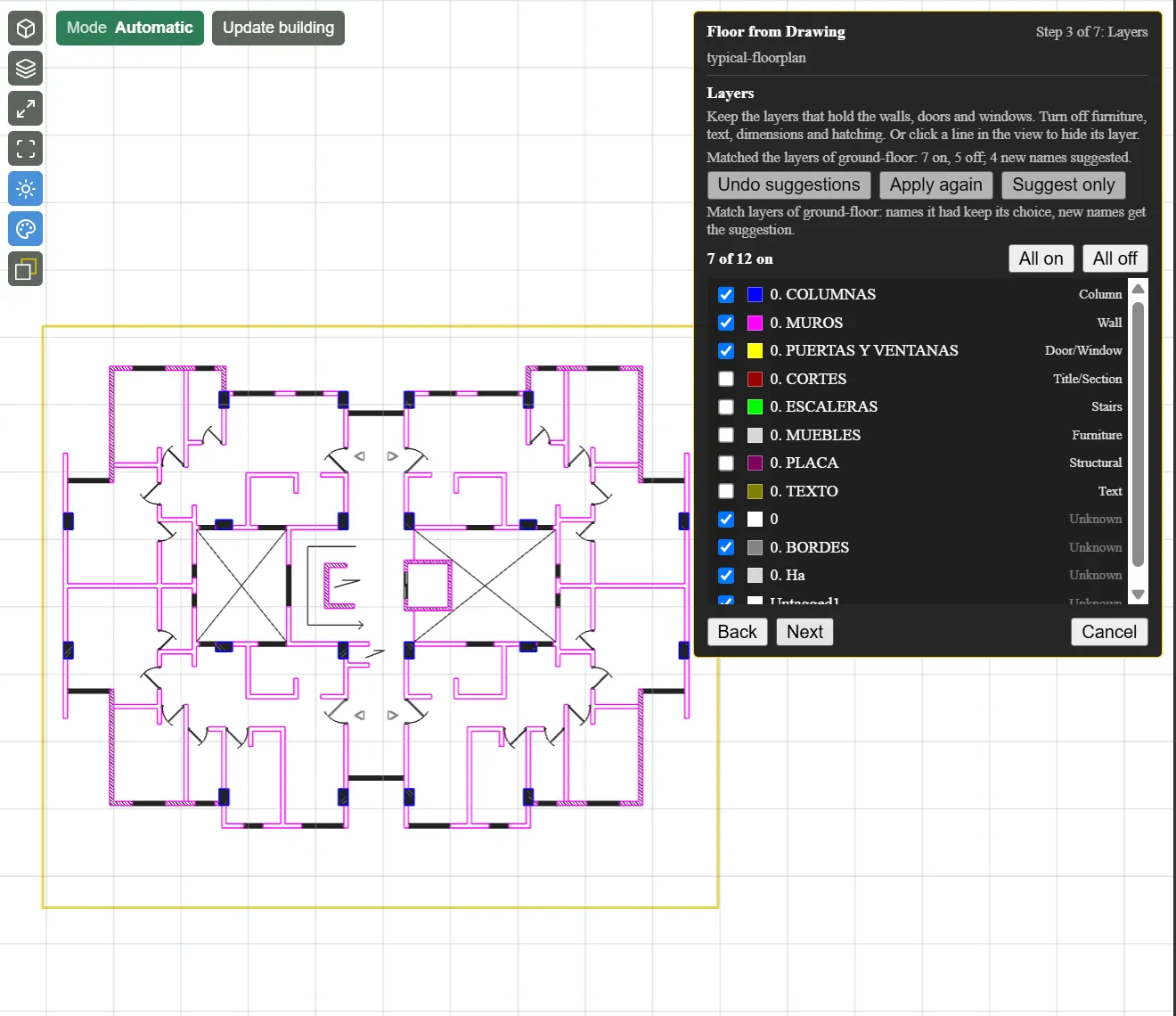
- Click Next.
Place
The Ground Floor now has Spaces, so EP3 places the typical plan on it automatically. The panel reads “Stack on Ground Floor”, “Placed at the best match automatically.” and “Exterior walls: 84% coincide with Ground Floor as placed.” The Ground Floor’s outline is drawn blue and this plan’s outline orange. They differ at the east and west ends, where the typical floors step in.
- In Floor name, type
Typical. - Check that Ceiling height is 2.9, Floor multiplier 8, and Starts at (m) 2.9.
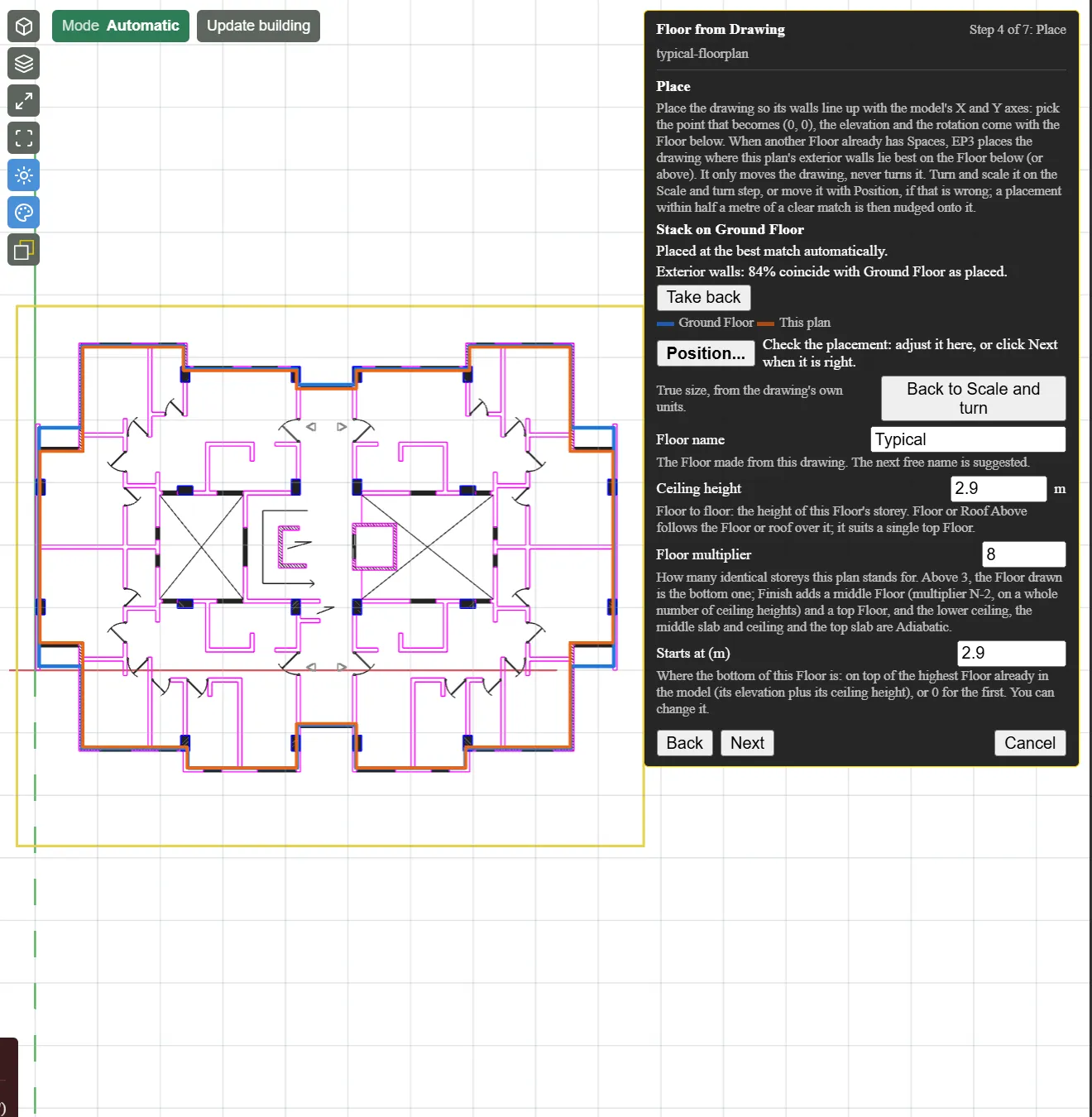
- Click Next.
Exterior walls
The status reads Outline closed, with the note “1 outline edge moved onto Ground Floor’s exterior walls, so the walls stack.” An outline side that lies close to a wall of the Floor below is moved onto it, so the walls of the two Floors line up.
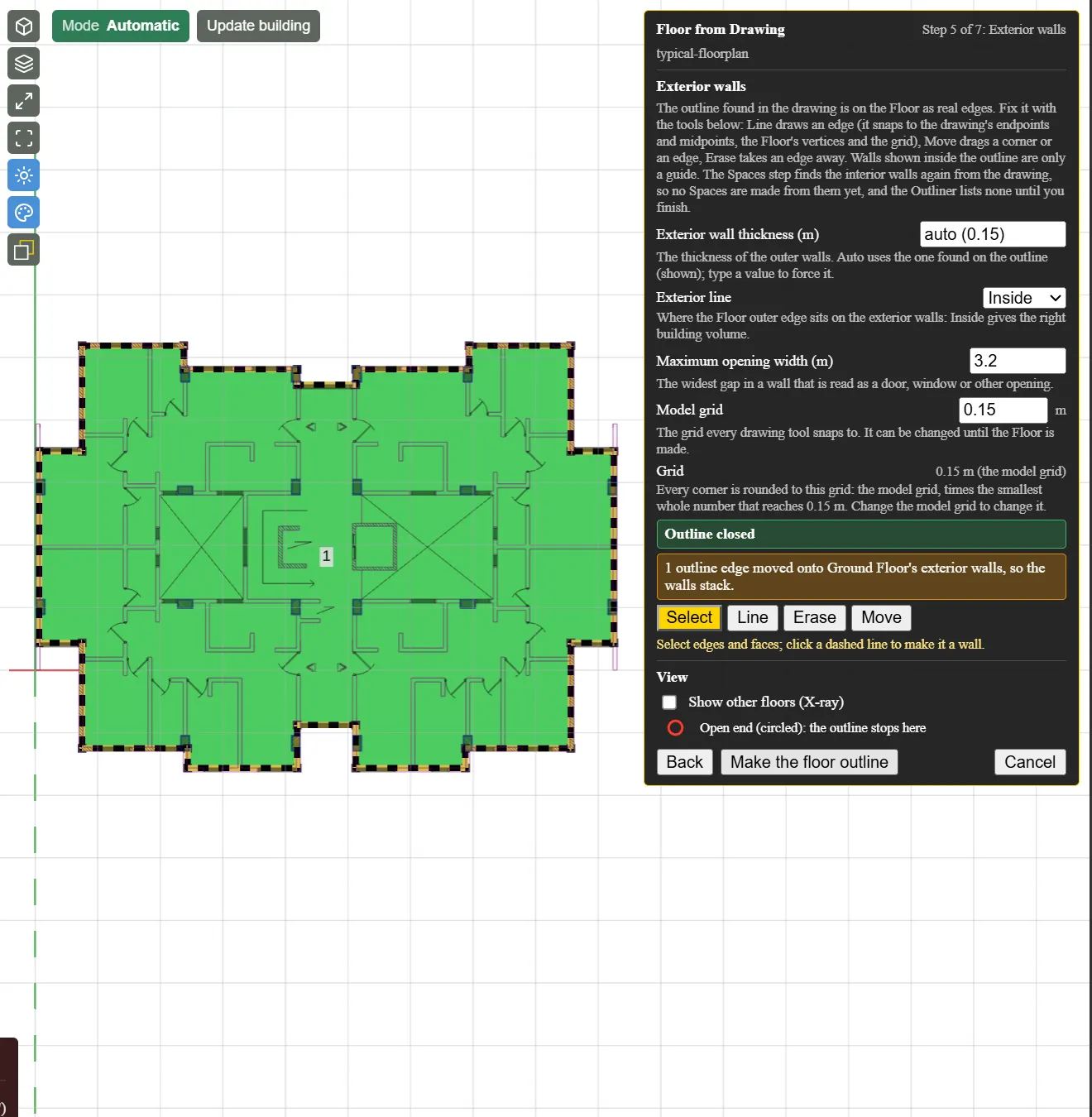
- Click Make the floor outline.
Spaces
The step opens at “16 Spaces, 2 voids, no dangling ends”. On this plan EP3 makes the two light wells voids by itself. Merge small spaces (1) offers to join a small Space, the shaft beside the east light well, to its neighbour.
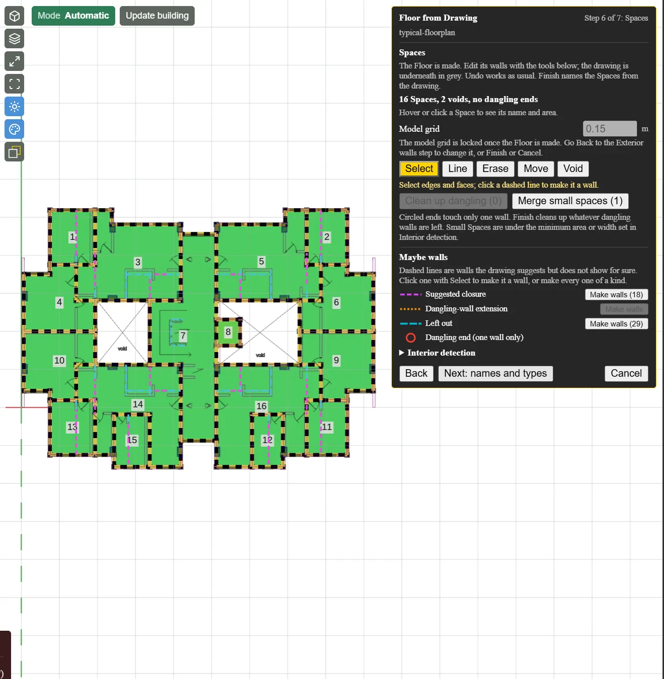
- Click Merge small spaces (1).
- Click Erase.
- In each north apartment, drag across the wall that splits off its small room beside the light well.
- In each south apartment, drag across the row of walls that separates its rooms and the service room beside it.
The summary reads “9 Spaces, 2 voids, 8 dangling ends”.
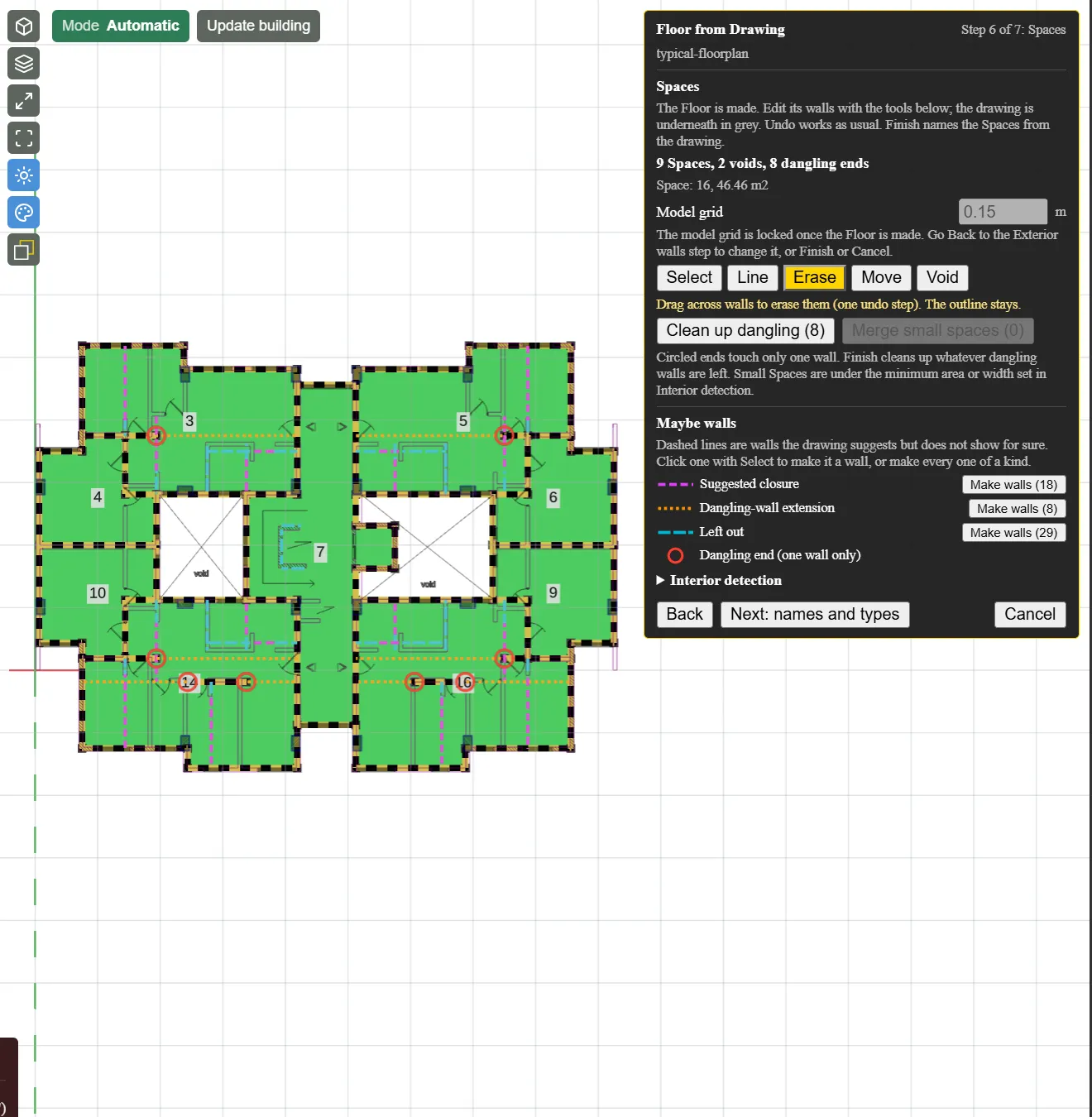
- Click Clean up dangling (8).
- Click Select.
- Click Next: names and types.
Names and types
The corridor is row 5 here.
- Tick rows 1, 2, 3, 4, 6, 7, 8 and 9.
- Choose Residential Apartments and click Set Space Type.
- Type
Apt #in the name box and click Set names. - Click Select none.
- Tick row 5.
- Choose Residential Circulation and click Set Space Type.
- In row 5’s Name box, replace 5 with
Corridor and stairs.
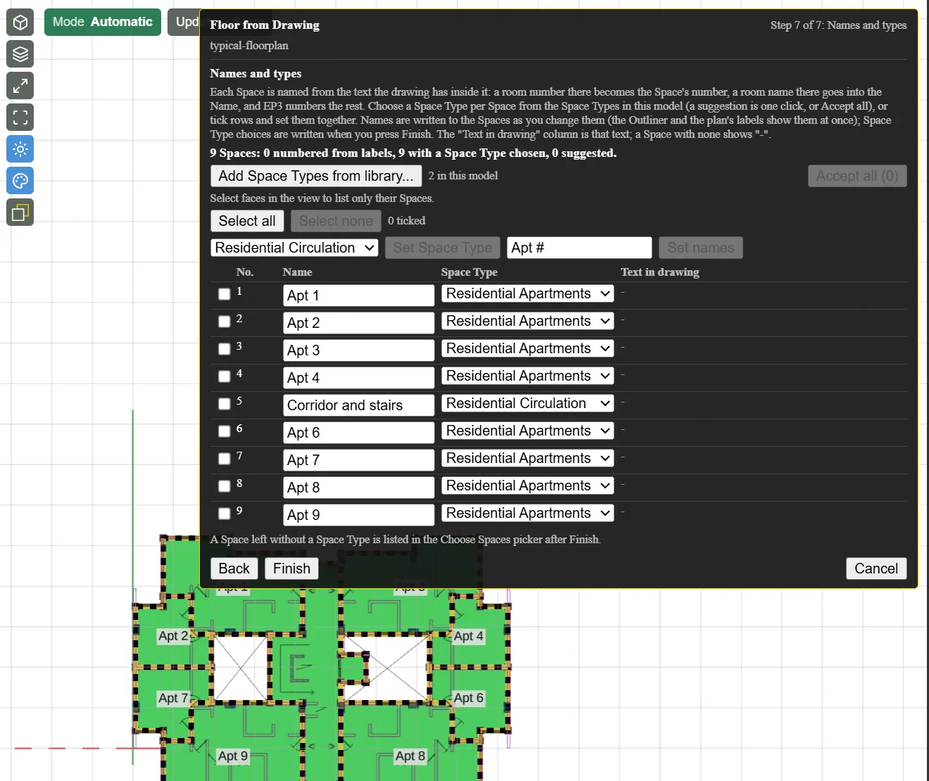
- Click Finish.
The model already assigns Space Types by selection, so EP3 finishes without a question.
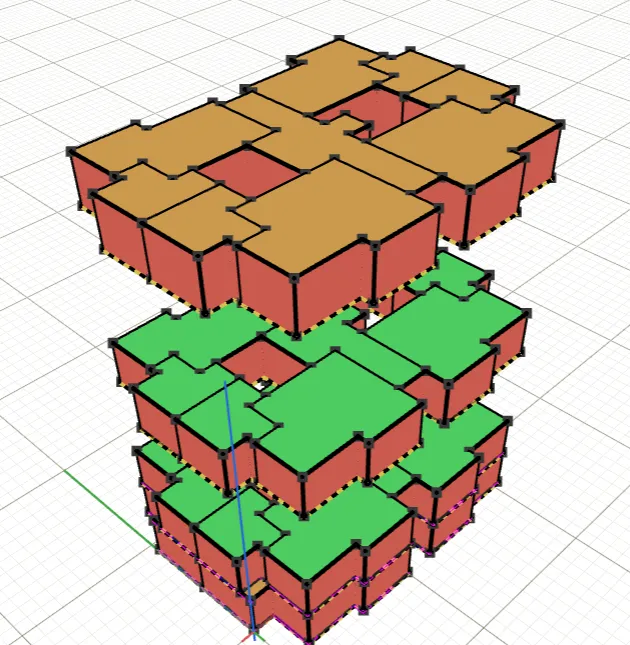
Bottom, Middle and Top
Finish makes three Floors from the typical plan, each with the same Spaces, names and Space Types:
- Typical Bottom at 2.90 m: the second storey.
- Typical Middle at 11.60 m, with a multiplier of 6: storeys three to eight. EnergyPlus counts each of its zones six times.
- Typical Top at 23.20 m: the ninth storey, under the roof.
The bottom Floor’s ceiling, the middle Floor’s floor and ceiling, and the top Floor’s floor are adiabatic, because the storeys they would touch are counted through the multiplier. The 3D view draws Typical Middle once, at a storey line partway up the stack, so gaps show above and below it.
Check the zone HVAC
The Model Wizard assigned Fan Coil to both Space Types. Check that the new zones have it.
- In the HVAC Outliner’s toolbar, click View Zone HVAC Assignments.
EP3 - Select Zone Conditioning Equipment opens on Assign HVAC Systems by Template. Each row carries the Fan Coil chip: Residential Apartments (28 zones) and Residential Circulation (4 zones). Each Floor counts once here, whatever its multiplier: four apartments on the Ground Floor and eight on each of the three typical Floors make 28 zones.
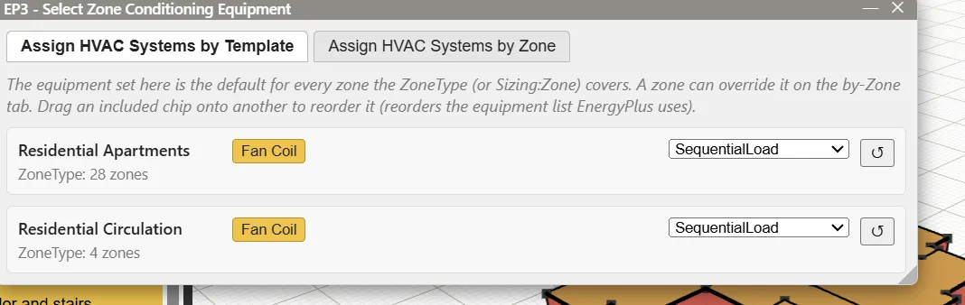
- Click Assign HVAC Systems by Zone to see each zone, such as “Ground Floor Apt 1 Zone”, with “thermostat: ok”. Here you can assign equipment to a single zone instead of through its Zone Type.
- Close the dialog.
- Save the model.
Place the windows from the elevations
Windows from Elevations finds the openings in the elevation drawings and puts a window or door on the walls for each one. Where a floor plan also shows the windows, the plan sets each window’s position along the wall and the elevation sets its size and sill height. Walls that no drawing shows get assumed windows.
Import the elevations
- In the Outliner, click + on the Elevations row.
- Choose North.dxf.
In the Import Elevation: North.dxf dialog, This elevation faces: already shows North, read from the file name.
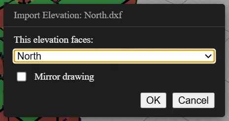
- Leave Mirror drawing clear.
- Click OK.
Position Background starts, with the bar “Rotate: click the drawing to turn it 90° (as many times as needed). Enter or Tab when it is the right way up (Shift+Tab goes back).”
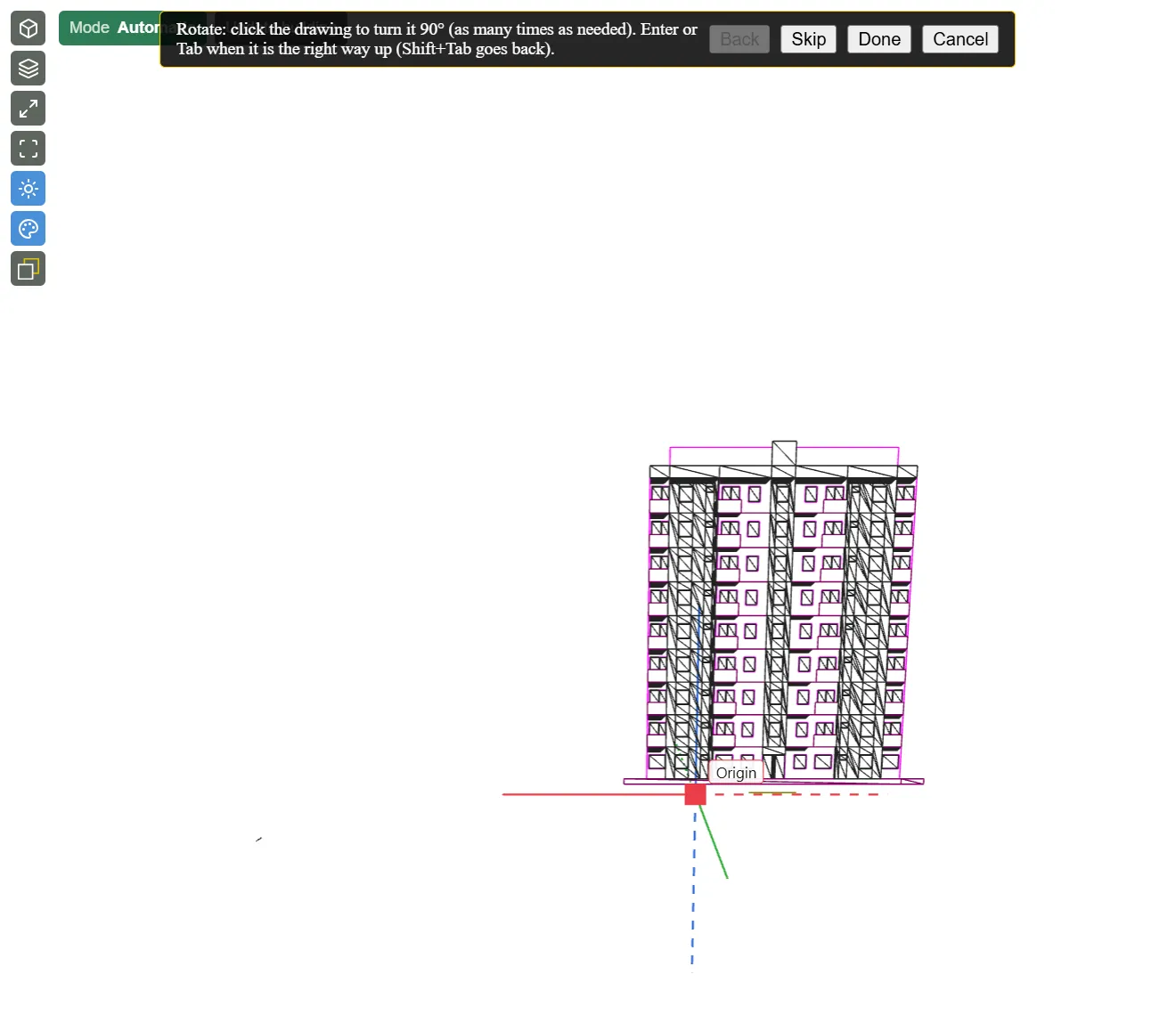
- Click Skip. The drawing is already the right way up.
- At “Position: click a reference point on the drawing. Tab to skip.”, click the lower-left corner of the facade at ground level.
- Click the matching corner of the building, at the bottom of the Ground Floor’s north wall.
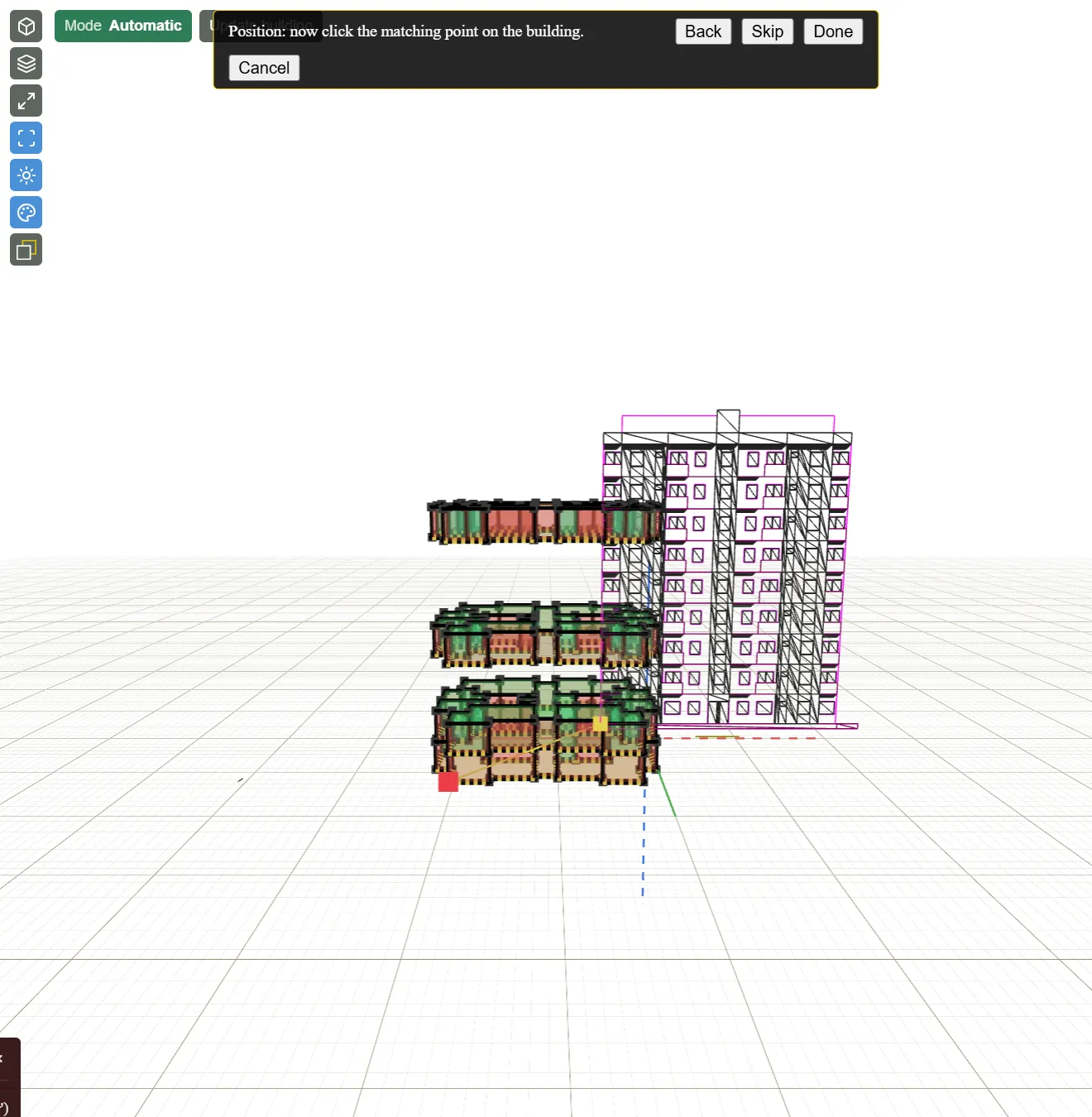
The placement can be rough. Windows from Elevations lines each elevation up with the floor plans automatically.
- Import South.dxf the same way, and check that This elevation faces: shows South. On the position step, click the lower-left corner of the facade, then the origin, which is the south-west corner of the building.
The Outliner now lists the North and South elevations under Elevations.
Choose the layers
- On the Elevations row, click ▦ (Windows from Elevations…).
Layers is one list for both elevations; each layer is marked “in 2 elevations”. EP3 suggests which layers to read from their names: the walls (0. MUROS) and the doors and windows (0. PUERTAS Y VENTANAS) are on, and text (0. TEXTO) is off. 0. PLACA is read as Structural and turned off.
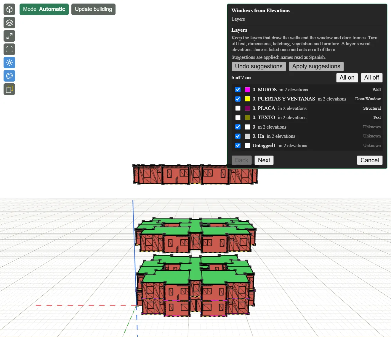
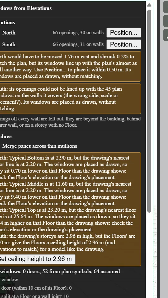
A layer’s name does not always say what it holds, and every office organises its drawings differently. Before you go on, check the suggested layers against what each layer actually contains. In these elevations, 0. PLACA draws most of the window frames. With it off, EP3 finds only 66 of the 99 openings in each elevation and cannot line the elevations up with the floor plans:
- Tick 0. PLACA.
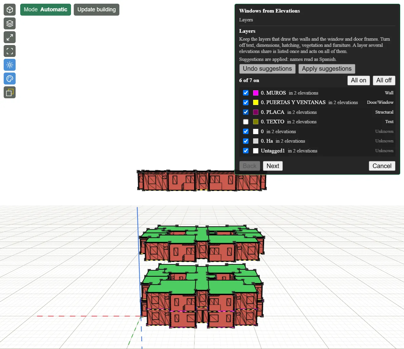
- Click Next.
Tip: If the Preview finds fewer openings than you can count on the drawing, go Back to Layers and look for a layer that draws the window frames.
Review the preview
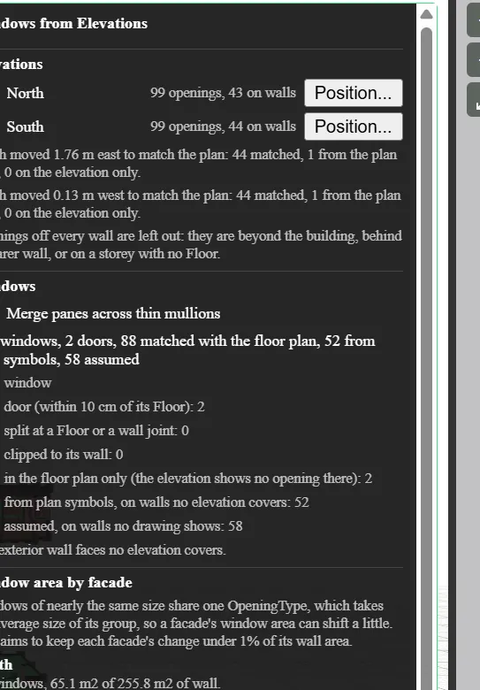
Each elevation now has 99 openings: “99 openings, 43 on walls” (North) and “99 openings, 44 on walls” (South). The openings off the walls belong to the storeys that the Typical Middle Floor stands for: it is drawn once, so the drawing’s other storeys have no wall to land on. EP3 lines each elevation up with the floor plan’s windows automatically, with a shift of up to 3.00 m along the facade:
- “North moved 1.76 m east to match the plan: 44 matched, 1 from the plan only, 0 on the elevation only.”
- “South moved 0.13 m west to match the plan: 44 matched, 1 from the plan only, 0 on the elevation only.”
The Floors’ 2.90 m storeys match the drawings, so there is no storey-height warning.
The counts line reads “198 windows, 2 doors, 88 matched with the floor plan, 52 from plan symbols, 58 assumed”.
- The 88 matched windows sit where the floor plans put them, with the elevation’s size and sill height.
- The 52 windows from plan symbols go on the east and west walls, which no elevation covers.
- The 58 assumed windows go on walls that no drawing shows at all.
- The 2 doors are the entrance doors. An opening whose bottom is within 10 cm of its Floor becomes a door.
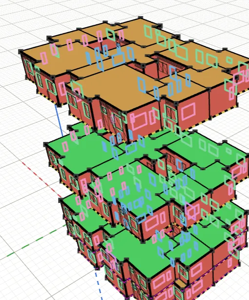
In the view, the window outlines follow the legend: green for windows, purple for doors, blue for windows from plan symbols, and pink for assumed windows.
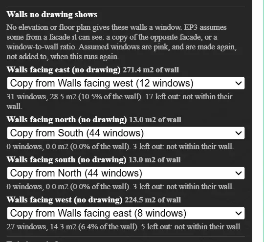
Walls no drawing shows lists the walls that neither an elevation nor a plan gives a window, grouped by the way they face. Each group copies the windows of a facade EP3 can see, takes a window-to-wall ratio, or gets none. Here the east-facing walls copy the west-facing walls, the west-facing walls copy the east-facing walls, and the short north- and south-facing pieces get no windows (“3 left out: not within their wall”).
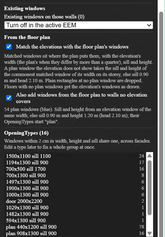
Leave the rest as it is: Existing windows on those walls (0) set to Turn off in the active EEM, and both checkboxes under From the floor plan on. OpeningTypes (16) lists the window sizes. Windows of nearly the same size share one OpeningType, so you can later change a whole group by editing its OpeningType.
Note: Position… beside an elevation is for an elevation whose line says it could not be lined up. Placing an elevation that already matches again can make its match worse.
Create the windows
- Click Create.
The status bar reads “Made 200 windows (2 doors) on 16 OpeningTypes; 58 assumed on walls no drawing shows.”
Hide the drawings and check the model
- Click the eye button on the Elevations row (“Hide ALL elevations”).
- Click the eye button on the Floor Plans row (“Hide ALL floorplans”).
Note: Hide drawings with the eye buttons. The ✕ on an Outliner row deletes the drawing without asking first.
The finished building shows its nine storeys as four Floors, with windows on every facade.
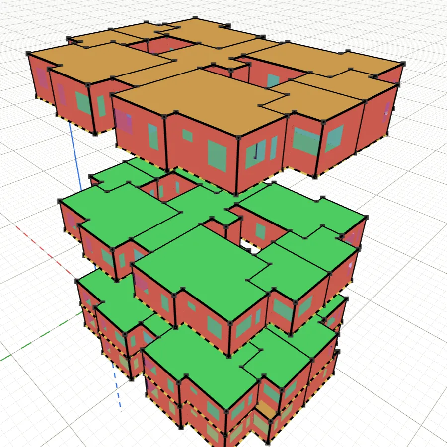
To compare the windows with the drawings, show the elevations again and click the button on the Elevation Wrap row (“Turn Elevation Wrap on”). Each elevation is projected onto the walls it faces.
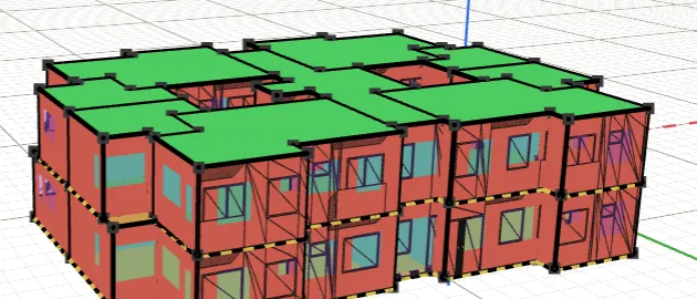
Turn Elevation Wrap off and hide the elevations again before you go on. Then run Model Validation.
- In the top toolbar, click Check the model for common issues.
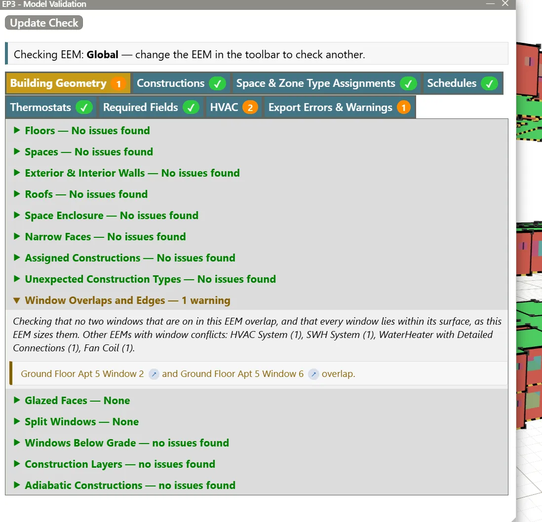
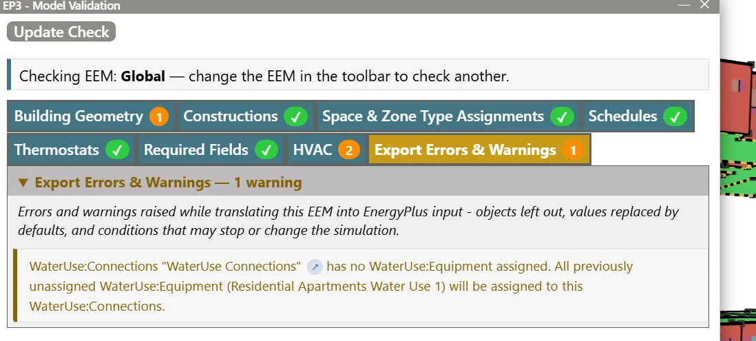
EP3 - Model Validation opens and checks the Global EEM. Constructions, Space & Zone Type Assignments, Schedules, Thermostats and Required Fields each show a tick. Building Geometry has one warning, under Window Overlaps and Edges: two windows of the Ground Floor’s Apt 5 overlap.
- Click HVAC.
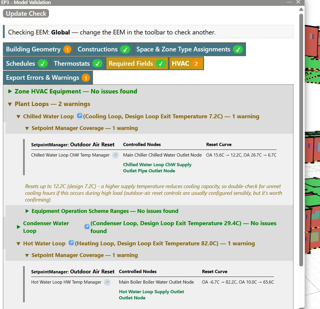
Zone HVAC Equipment reports no issues. The two warnings under Plant Loops are Setpoint Manager Coverage notes on the Chilled Water Loop and the Hot Water Loop: the Fan Coil system resets the supply water temperatures with the outdoor air temperature, which lowers the plant’s capacity in mild weather. Keep them in mind if a simulation shows unmet hours.
- Click Export Errors & Warnings.
The one warning says that the service water connections have no water use equipment yet, so EP3 assigns the Residential Apartments water use to them when it writes the EnergyPlus input.
- Close the dialog.
- Save the model.
Next steps
- Run the model and read the results: Running Simulations, and Viewing and Interpreting Results.
- Every setting of both tools, including maybe walls, voids, the window matching rules and walls no drawing shows: Floors and Windows from CAD Drawings.
- Change a group of windows at once with its OpeningType: Windows, Shading, and Daylighting.
- Review the zones and their equipment: Spaces and Zones, and Zone-Level HVAC Equipment and Zone Sizing.
- What each Model Validation tab checks: Model Troubleshooting and Quality Assurance.