Model an existing building without drawings: pick it on a map, take its outline and storeys from OpenStreetMap, bring in the buildings around it as site shading, and place its windows from one street photo. The example is the Fairbanks, Morse and Company Building at 900 South Wabash Avenue in Chicago, a 1907 seven-storey office building with regular brick facades.
What you need
- EP3 3.0 and an internet connection. The map, the building data and the address search come from online map services.
- The photo of the building’s Wabash Avenue (east) facade: fairbanks-morse-wabash.jpg. Save it to your project folder.
- The weather file
USA_IL_Chicago-Midway.AP.725340_TMY3.epw(Chicago Midway, climate zone 5A, about 10 km from the site), from https://energyplus.net/weather. - About 60 minutes.
- The screenshots use SI units (m, °C).
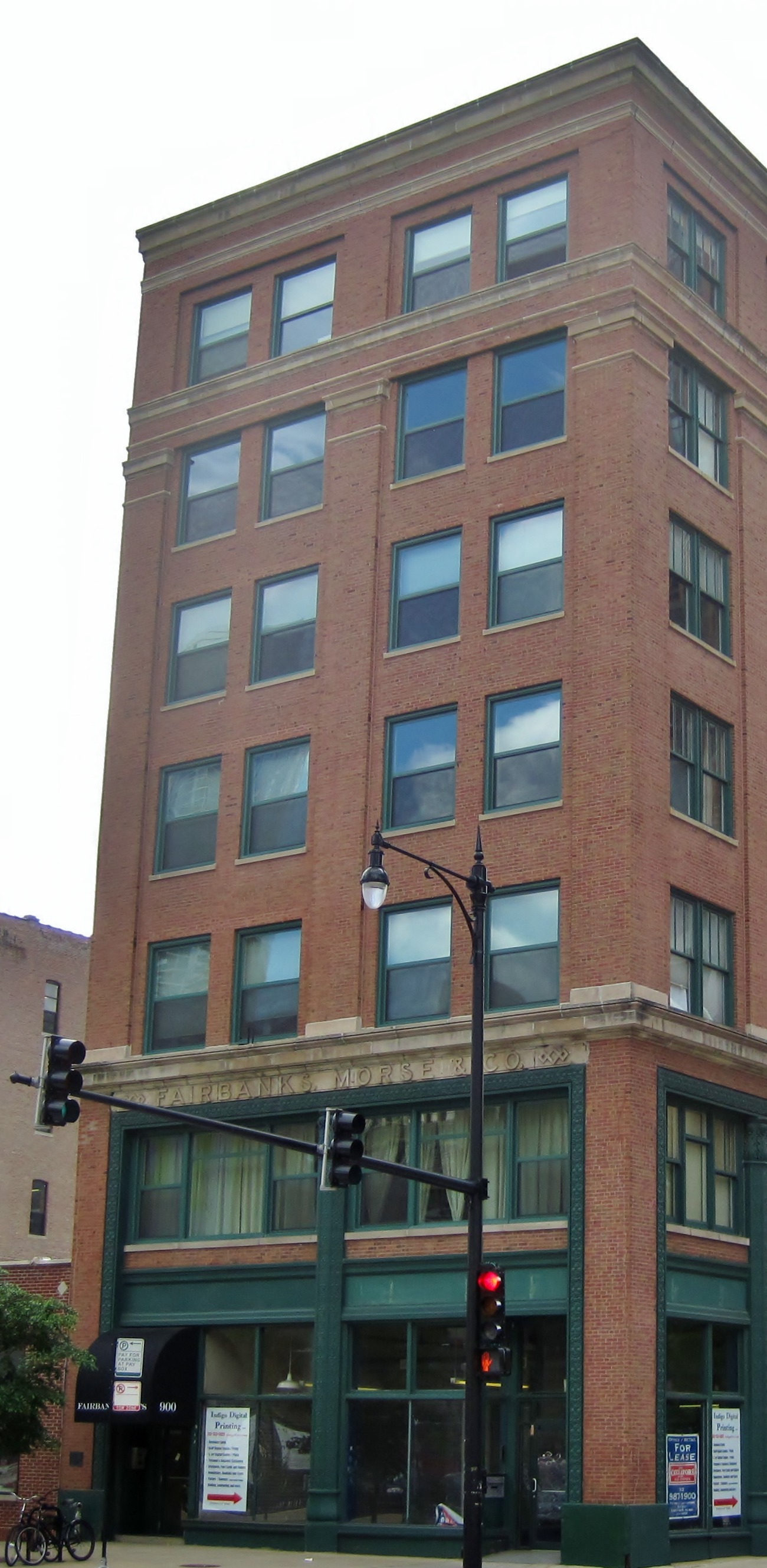
Note: Photo credit: “Fairbanks, Morse and Company Building” by Teemu008 from Palatine, Illinois, CC BY-SA 2.0 (https://creativecommons.org/licenses/by-sa/2.0), from Wikimedia Commons (https://commons.wikimedia.org/wiki/File:Fairbanks,_Morse_and_Company_Building_(7367623630).jpg). The download is cropped to the east facade and is shared under the same licence. Map data © OpenStreetMap contributors (ODbL); map pictures © OpenFreeMap, OpenMapTiles.

Set up the model with the Model Wizard
The Model Wizard opens when EP3 starts without a file, and each time you choose File > New.
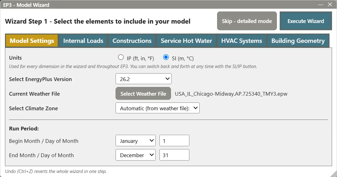
- On Model Settings, choose SI (m, °C) for Units.
- Click Select Weather File and choose
USA_IL_Chicago-Midway.AP.725340_TMY3.epw. - Leave Select Climate Zone at Automatic (from weather file). EP3 reads climate zone 5A from the weather file.
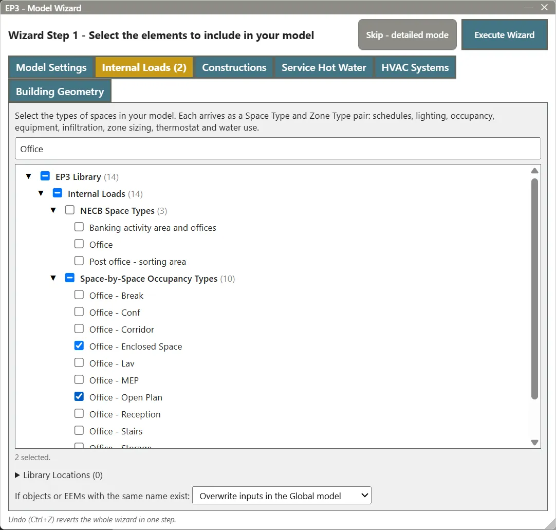
- On Internal Loads, type
Officein the filter box. - Under Space-by-Space Occupancy Types, tick Office - Enclosed Space and Office - Open Plan.
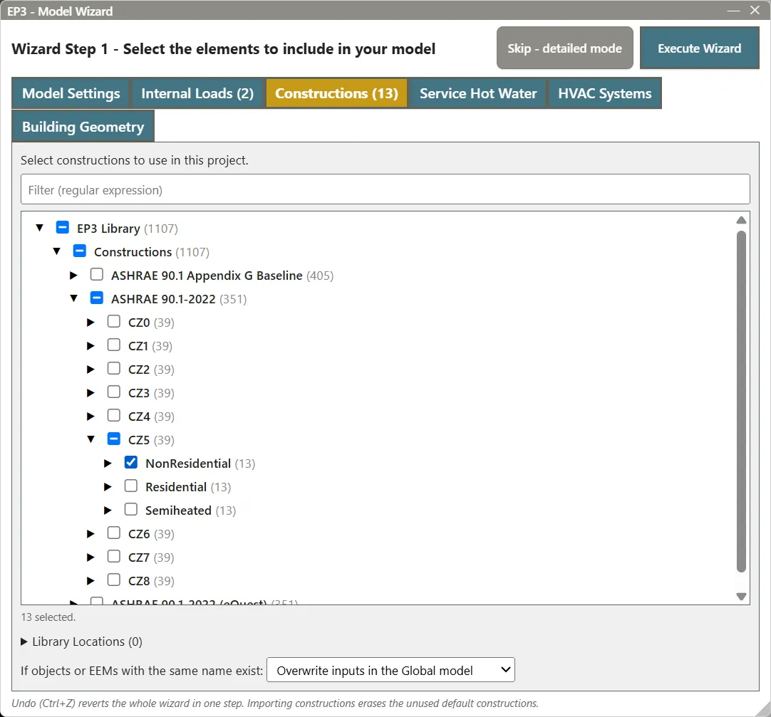
- On Constructions, expand EP3 Library > Constructions > ASHRAE 90.1-2022 > CZ5.
- Tick NonResidential.
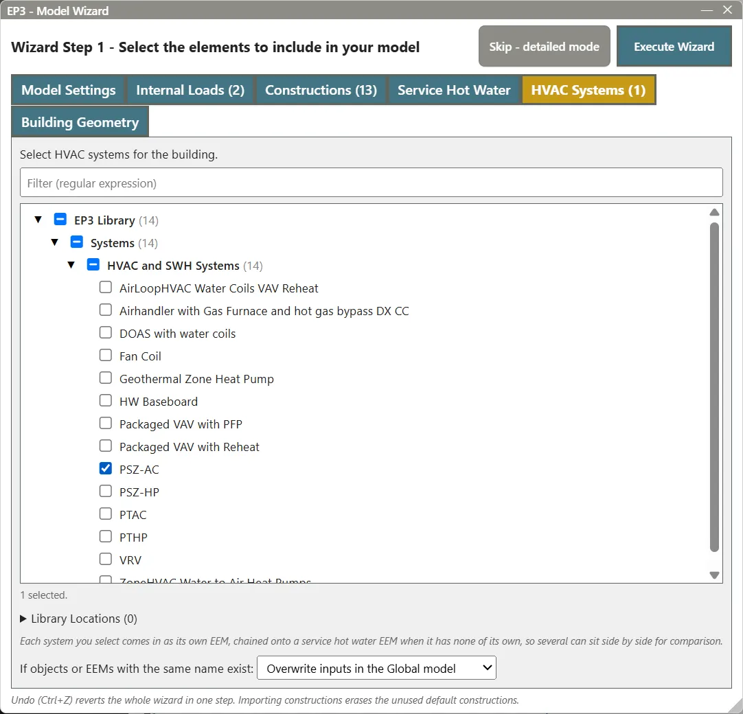
- On HVAC Systems, expand EP3 Library > Systems > HVAC and SWH Systems.
- Tick PSZ-AC (packaged single-zone air conditioner with a gas furnace).
- On Building Geometry, choose I want to draw my own building geometry.
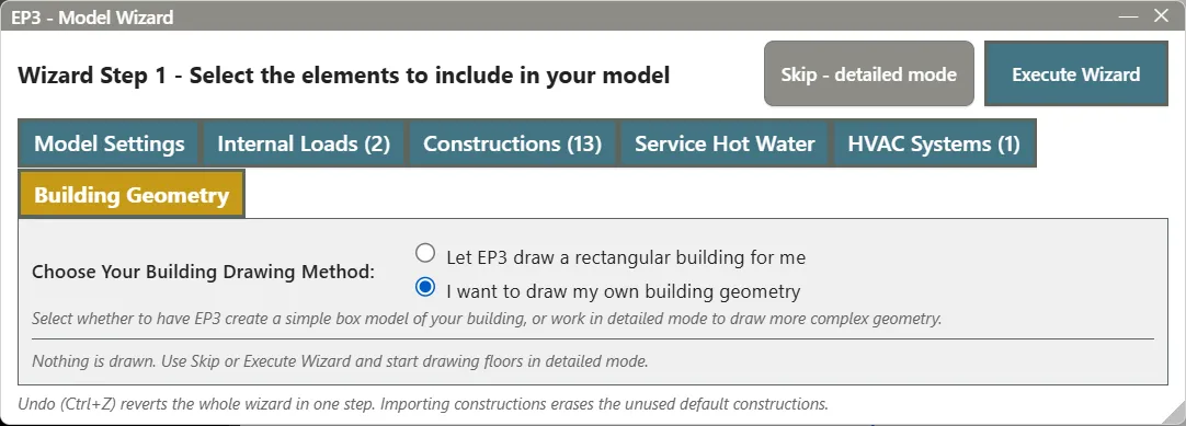
- Click Execute Wizard.
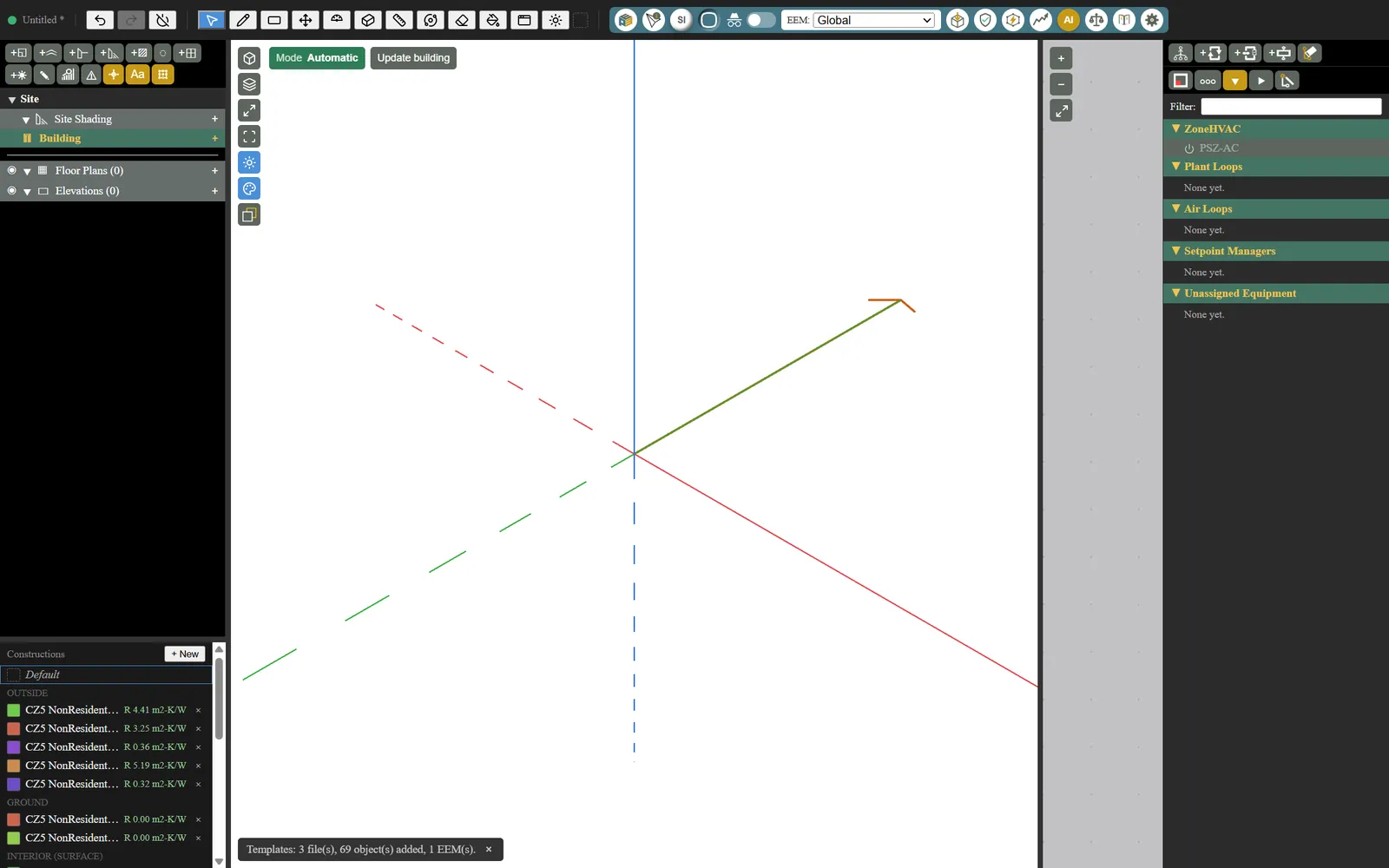
The button over the 3D view reads Mode Automatic, so EP3 makes the walls, roofs and constructions from the Floors. The PSZ-AC system arrives as an energy efficiency measure (EEM), a named variation of the model, called PSZ-AC.
- Drag the divider between the 3D view and the HVAC diagram to the right to give the 3D view more room.
Make the Building from the map
Turn on map lookups
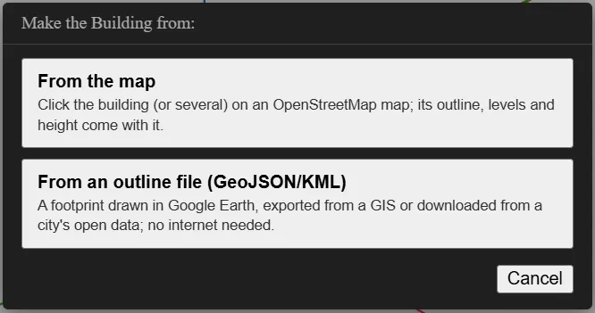
- In the Building Geometry Outliner, click + on the Building row (tooltip: “Make the Building from the map, or from an outline file (GeoJSON or KML), with its Floors and Spaces”).
- Under Make the Building from:, choose From the map.
The first time, Building from Map opens with map lookups off and a privacy note that says what is sent and where.
- Read the note and click Turn on.
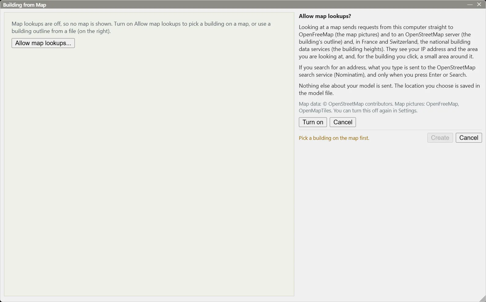
Note: EP3 sends only the area you look at and any address you search for, never your model. You can turn map lookups off again in File > Settings… > Map Lookups.
Find and pick the building
The map opens at the weather file’s station, Chicago Midway.
- In the search box above the map, type
900 South Wabash Avenue, Chicagoand press Enter. - Click the result under the search box. The map moves to the block.
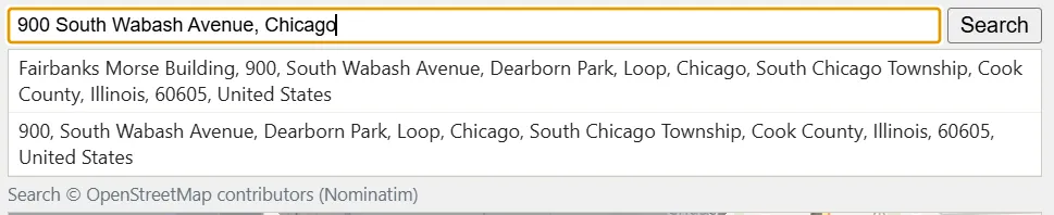
- Click the Fairbanks Morse Building, the northernmost building on the west side of Wabash Avenue at East 9th Street.
A progress bar names each step, such as “Step 2 of 4: Looking up the exact building outlines (OpenStreetMap)”. This can take about 30 seconds.
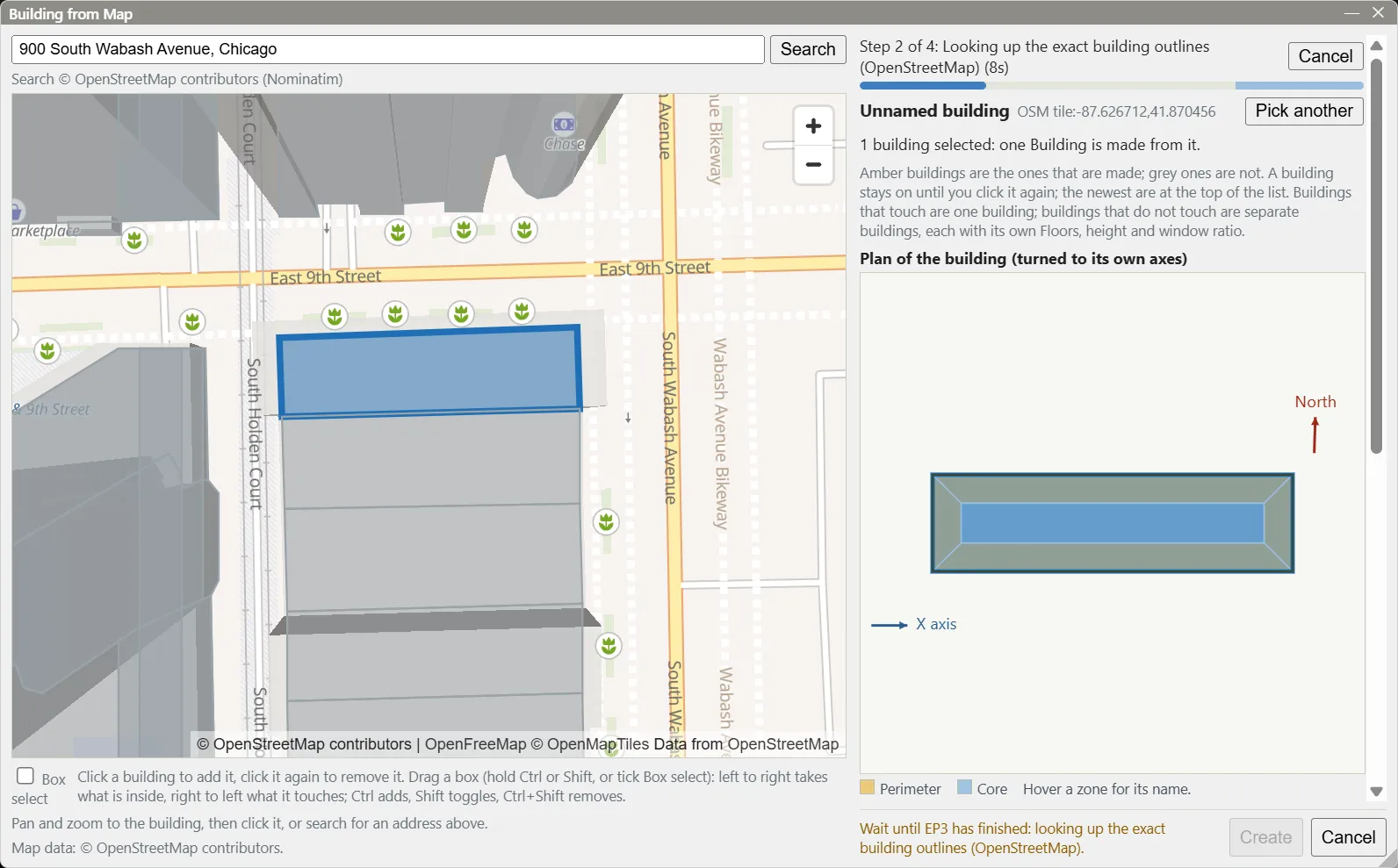
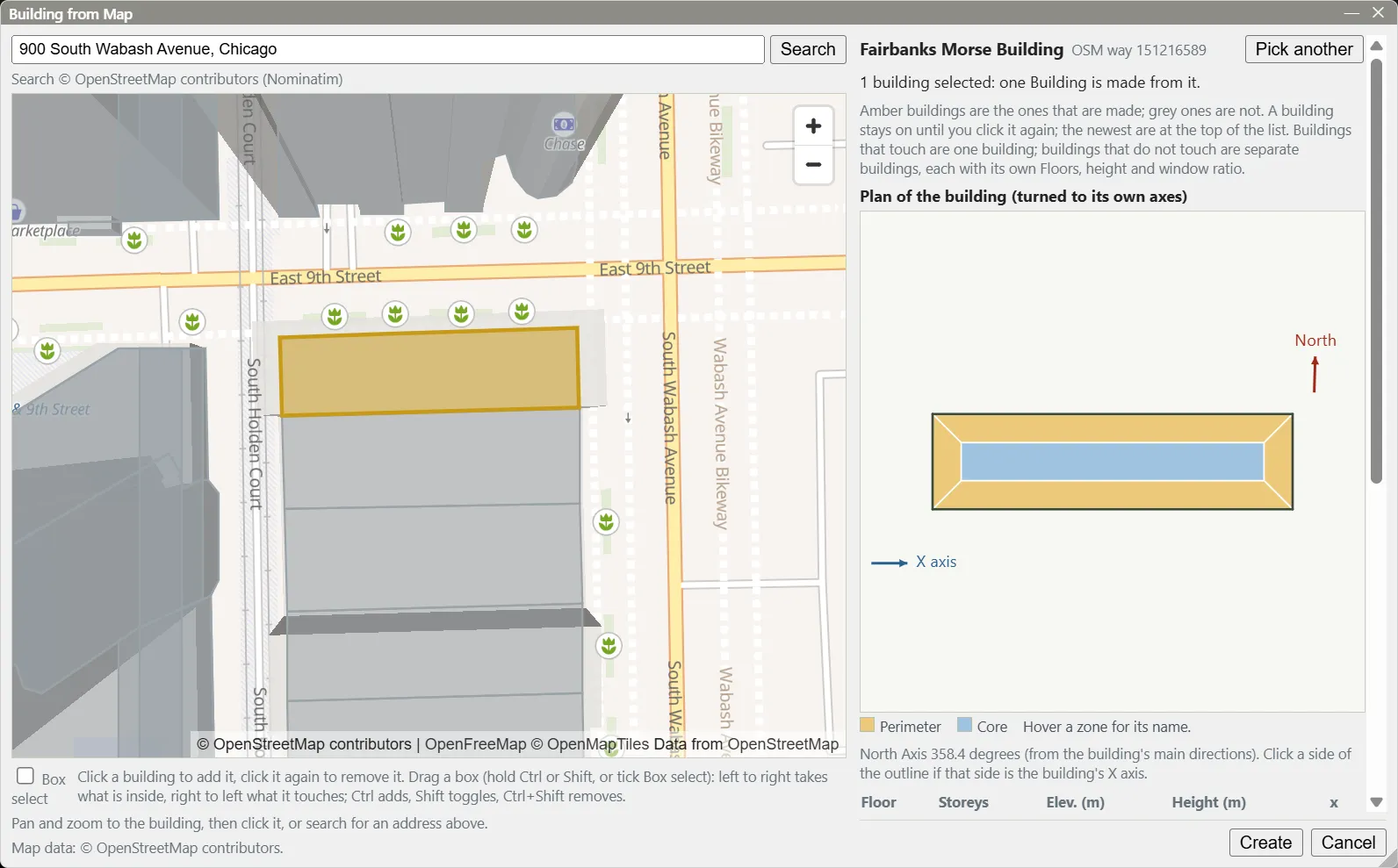
When it finishes, the pane on the right reads “Fairbanks Morse Building OSM way 151216589” and “1 building selected: one Building is made from it.” The building is amber on the map, and the plan shows a perimeter ring and a core. EP3 sets the North Axis to 358.4 degrees from the building’s main directions.
Tip: If the line “OpenStreetMap servers are busy; using the map’s outlines.” appears, the building is made from the map’s outline, which is accurate to about 0.5 m and has no levels. To try OpenStreetMap again, wait a minute and click the building twice (off and on).
Set the storeys and the zoning
OpenStreetMap gives this building 7 levels and no height, so the Source column reads “levels x 3” and EP3 assumes 3.5 m storeys. The photo shows a tall ground floor with a shop front and six office storeys above it.
- Scroll the right-hand pane down to the table of pieces.
- Set Floor-to-floor (m) to
3.7. - Set Ground floor (m) to
5.9.
Height becomes 25.9 m and its source “set by you”. The Floors table above now lists F1 (5.9 m), F2, F3-6, and F7. The four identical middle storeys become one Floor, F3-6, with a multiplier of x4.
- Leave Zoning at Core and perimeter and Perimeter depth (m) empty (4 m).
- Set Window-to-wall ratio (%), for every building without its own to
0. The photo will place the windows. - Set Perimeter Space Type to Office - Enclosed Space and Core Space Type to Office - Open Plan.
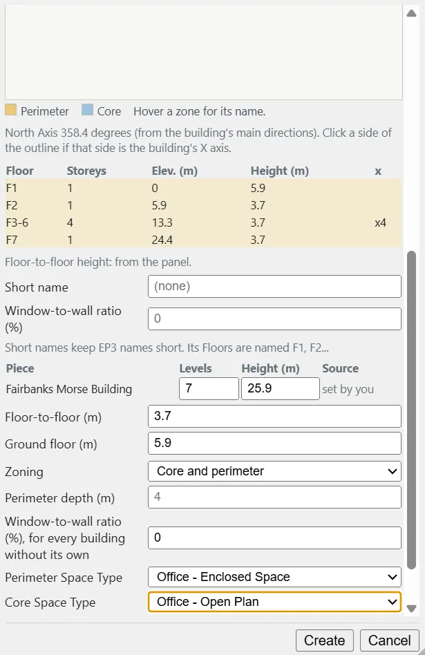
- Click Create.
EP3 makes 4 Floors and 20 Spaces in one undo step. The south wall stands against the building next door, which you did not pick, so EP3 makes it adiabatic. The summary reads “Made the building from the map: 4 Floors, 20 Spaces; 1 wall against 1 touching building made adiabatic.” Adiabatic walls never get windows.
Add the neighbours as site shading
After Create, the dialog goes straight on to Neighbouring Buildings, at the same place on the map. Your building is outlined in amber.
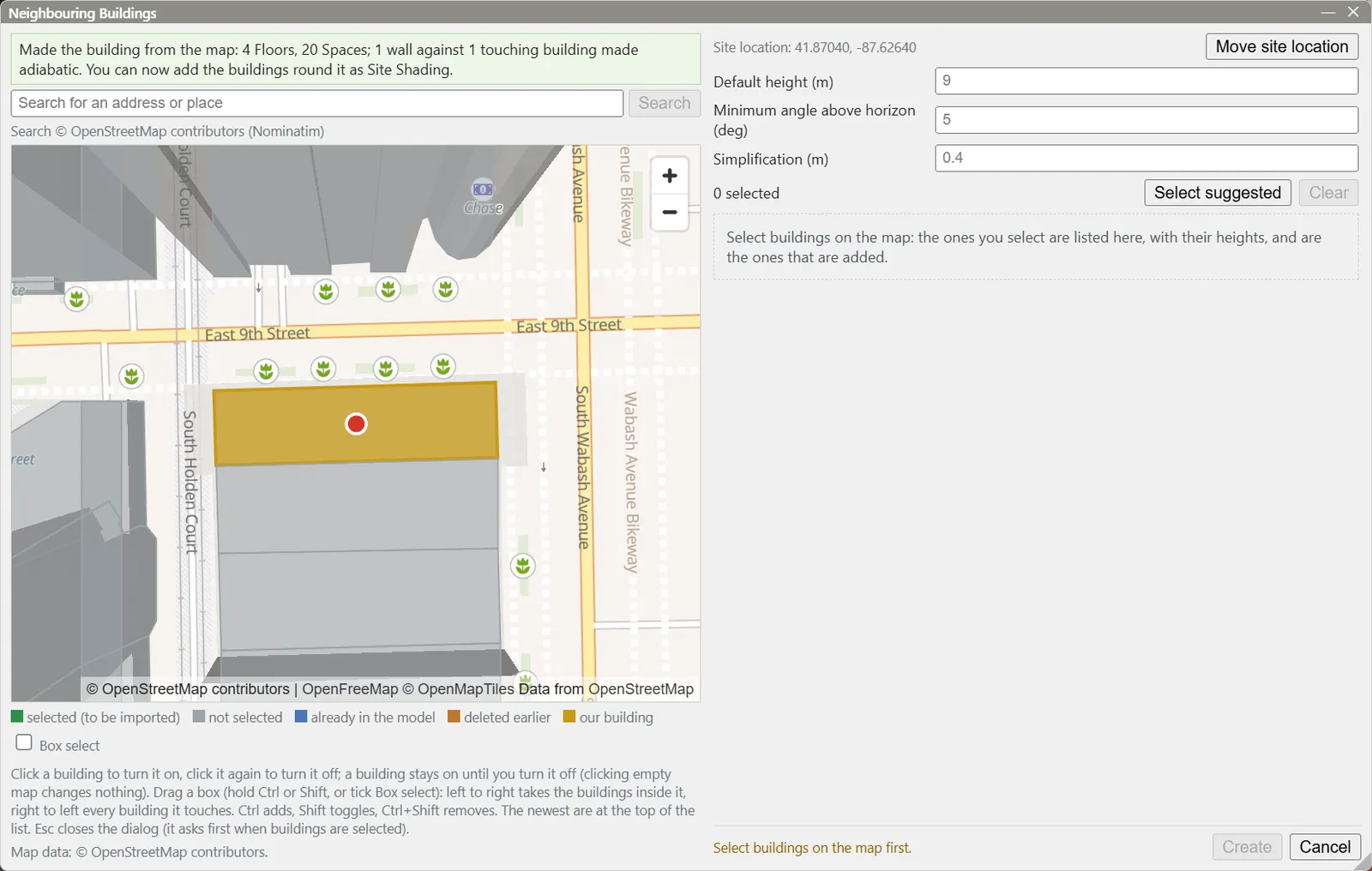
- Zoom out one step with − on the map, so the buildings within 100 m show.
- Click Select suggested.
EP3 selects the buildings within 100 m whose tops rise more than the Minimum angle above horizon (5 degrees) seen from your building. Here it selects 13 buildings with 129 faces. The list shows each one’s distance, Height (green: OSM height), angle and faces. The line “1 wall against neighbours become adiabatic” counts your party wall.
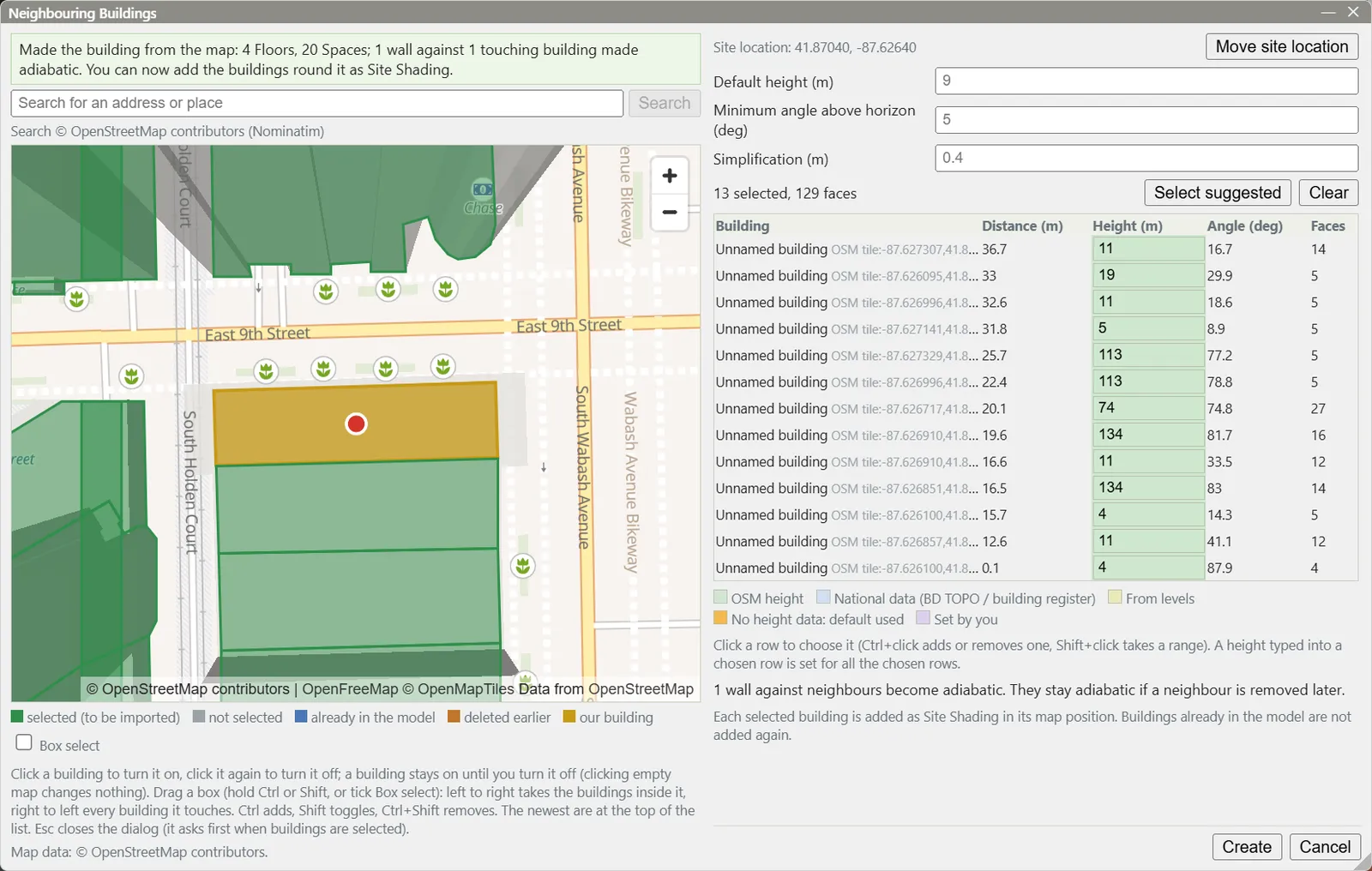
- Click Create.
EP3 reads the exact outlines from OpenStreetMap and adds each neighbour as a separate Site Shading object. The status line gives the count, for example “Added 7 neighbouring buildings (97 faces).” Pieces of one building on the map come in as one neighbour, so the count is lower than the number selected.
- Click View Iso in the 3D view’s toolbar to see the block.
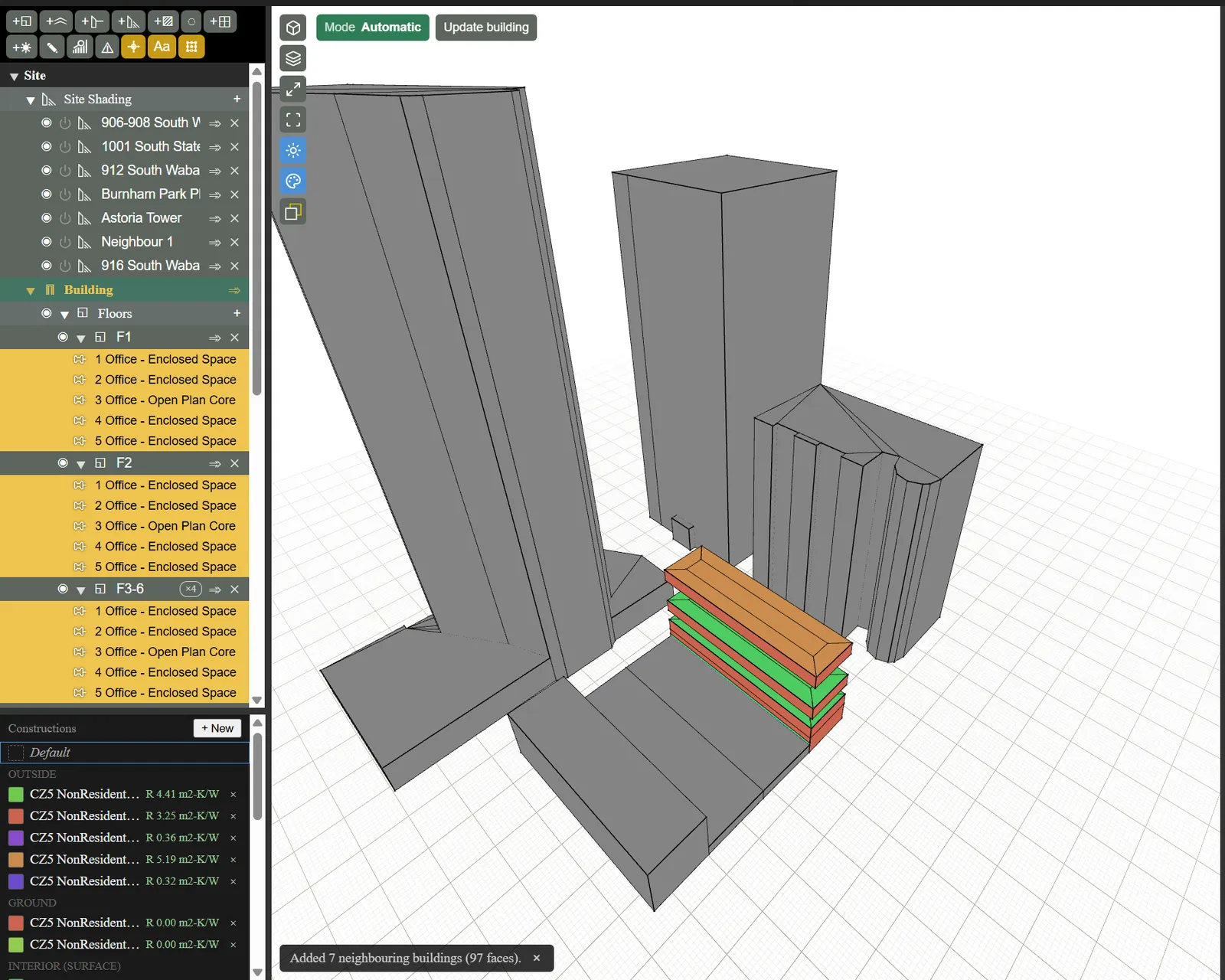
Tip: Each neighbour can be turned off in an EEM like any other object, so you can study the building without its tall neighbours by adding one EEM.
- Save the model as
FairbanksMorse.ep3in your project folder.
Import the photo as an elevation
The photo looks up at the building from the street, so its vertical lines lean in. Position Background straightens it onto the east wall with four pins.
- In the Outliner, collapse Site Shading and Building to see the Elevations row.
- Click + on Elevations (0) (tooltip: “Import an elevation (image or PDF)”) and choose
fairbanks-morse-wabash.jpg. - In Import Elevation, choose East for Elevation and click OK.
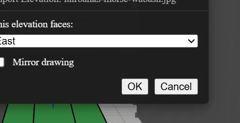
The photo stands beside the building and Position Background starts with Rotate. The photo is already upright and the pins are easier to place with the neighbours hidden, so leave the tool for now.
- Click Cancel.
Straighten the photo with pins
- Click Enter this context on the Building row.
- Press Shift+R (Isolate active context) so only the Building shows.
- Under Elevations, click Position Background on the
fairbanks-morse-wabashrow. - Press Tab to skip Rotate, and Tab again to skip Scale from length.
The bar reads “Position (pin 1): click a reference point on the drawing. Tab to skip.”
- Zoom in on the facade. Click the photo at the bottom-left corner of the building, where the brick pier meets the sidewalk.
- Click the matching corner of the model: the bottom of the east wall at its left (south) end. The point snaps to the vertex.
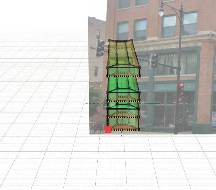
The bar now reads “Scale to model (pin 2): click a point on the drawing. Tab to skip to the pins.”
- Click the photo at the top-right corner of the facade, under the cornice where the brick wall ends.
- Click the matching corner of the model: the top of the east wall at its right (north) end.
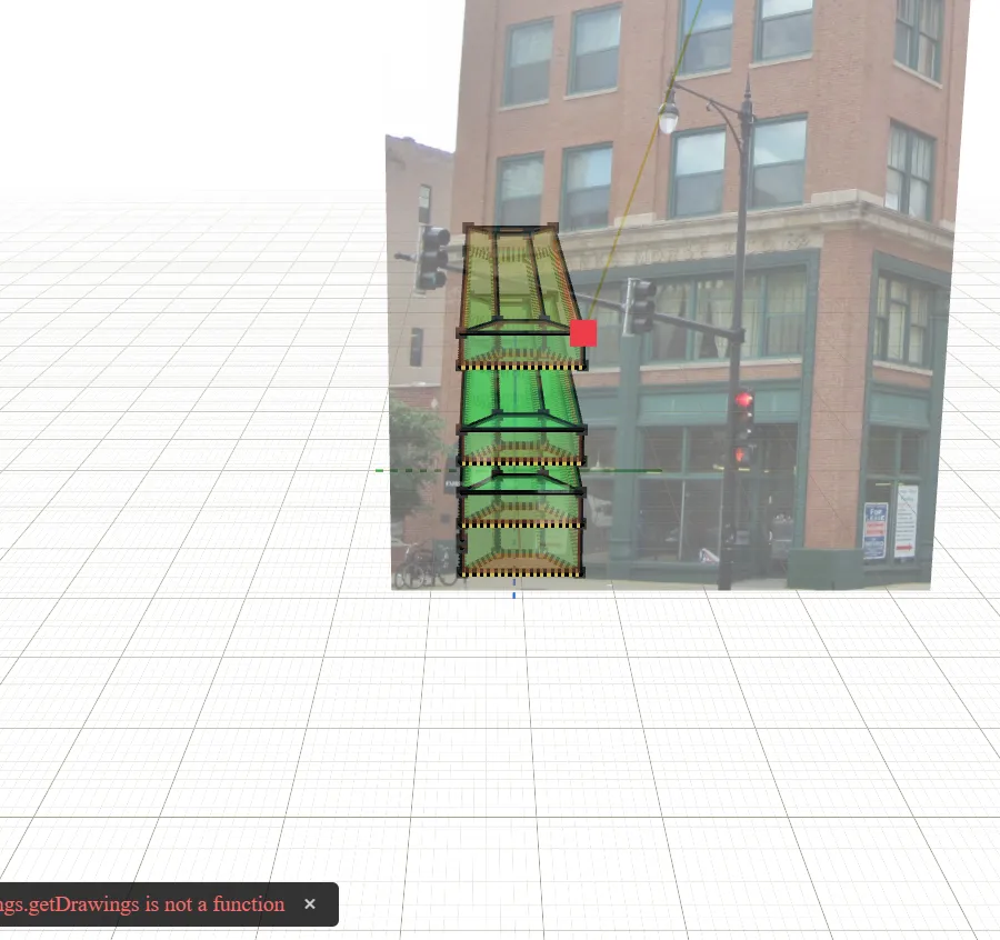
The Pins step opens with four pins: pin 1 blue and pin 2 orange where you clicked, pin 3 green and pin 4 purple at corners of the picture.
- Pin 3 sits on the photo’s lower-right corner, which is a neighbouring shop. Hold Shift and drag pin 3 along the photo to the bottom-right corner of the building, where it meets the sidewalk. Shift+drag moves the point the pin holds without bending the picture.
- Drag pin 3 (no Shift) to the model’s north-east corner at ground level. It snaps to the vertex.
- Shift+drag pin 4 to the top-left corner of the facade, under the cornice.
- Drag pin 4 to the top of the model’s south-east corner.
The picture bends so the building’s edges stand straight on the wall. Move the Transparency slider to see the model through it.
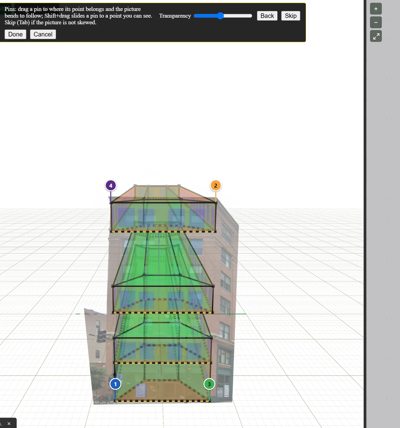
- Click Done.
Tip: Pin points on the plane of the wall, such as wall and window corners. A cornice, a balcony or a bay stands out from the wall and shifts against it as the camera angle changes.
Find the windows from the photo’s colours
- On the Elevations row, click Windows from Elevations….
The Colours step shows the photo, “fairbanks-morse-wabash, 1 of 1”, with the view turned to face it.
- Click Pick beside Wall colours and click a plain stretch of red brick between two windows.
- Click Pick beside Window colours. Click the glass of several windows: a dark pane, a pane reflecting blue sky, a light pane reflecting cloud, and the dark green glass of the shop front. Each click adds a colour to the list.
- Click Click the picture… to stop picking.
The picture is tinted green where it matches a window colour and orange where it matches a wall colour. Point at a colour in a list to see only what it matches.
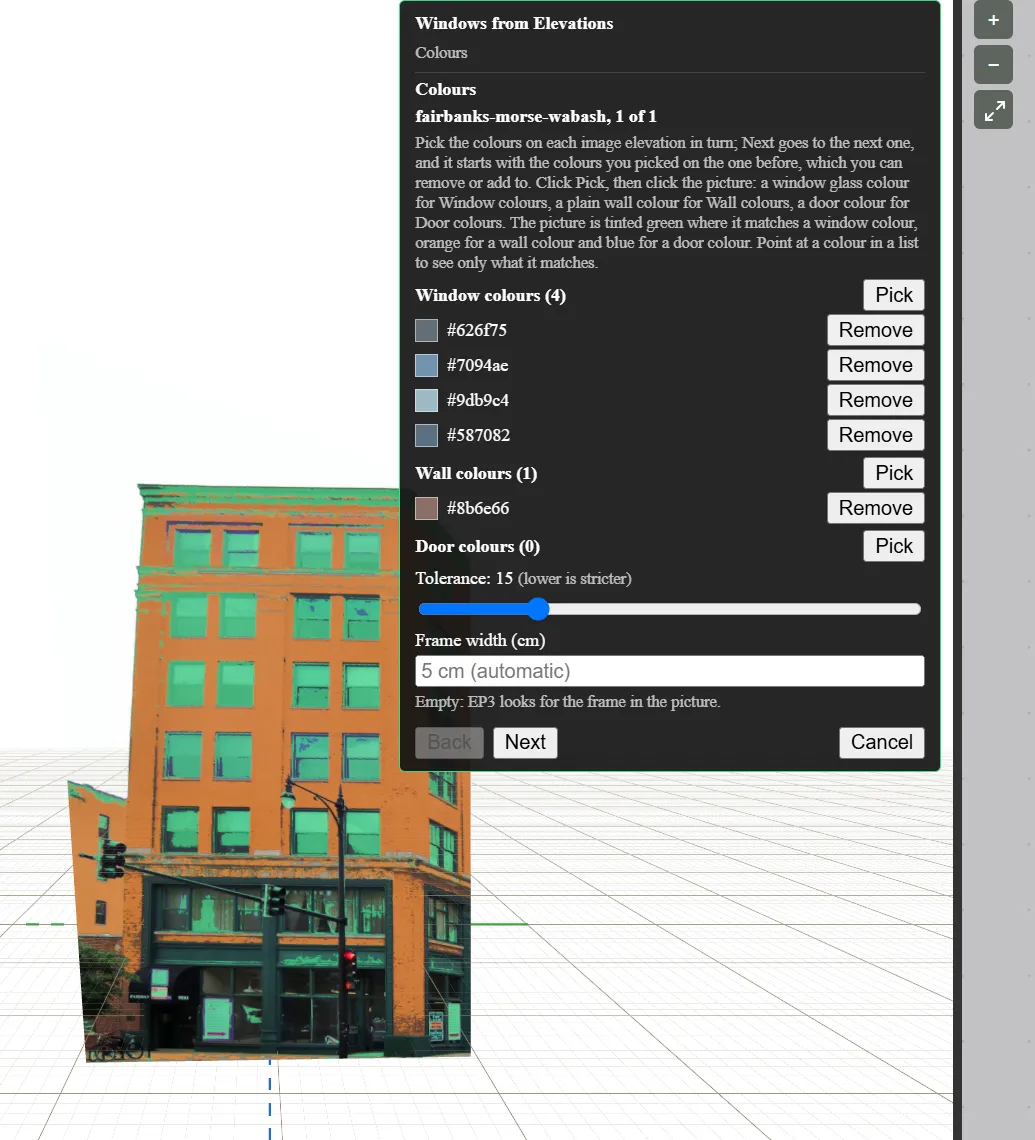
Tip: A photo has shadows and reflections, so one glass colour rarely covers every window. Add the colours of the windows that stay untinted. Raise Tolerance only a little at a time: a high tolerance lets the brick match the darker glass.
- Click Next.
The Preview draws the windows on the walls and counts them: 10 windows on the photographed facade, about 25.5 m² of 225.9 m² of wall.
Choose windows for the walls no drawing shows
The photo shows only the east facade. Under Walls no drawing shows, EP3 lists the north, south and west walls. The west wall defaults to Copy from fairbanks-morse-wabash, because it faces the photographed facade. The north and south walls default to Window-to-wall ratio.
- For Walls facing north (no drawing), choose Copy from fairbanks-morse-wabash.
- Do the same for Walls facing south (no drawing).
EP3 repeats the photographed facade’s windows evenly along the longer walls. The south wall is the adiabatic party wall, so it gets no windows from either choice. Assumed windows are pink in the 3D view.
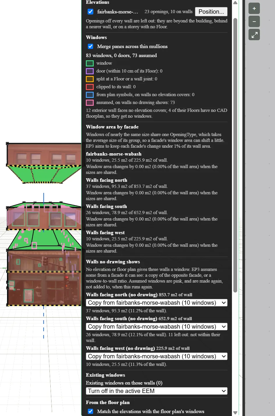
- Click Create.
The status line reads “Made 83 windows (0 doors) on 10 OpeningTypes; 73 assumed on walls no drawing shows.” Windows that are close in size share an OpeningType, so you can change a group of them at once later.
Remove the stray windows
The colour finder also takes small patches of glass-coloured pixels for windows: here a sign and the street lamp on the ground floor, and the traffic signals and the lamp’s reflections on the second floor. Because the north and west walls copy the photographed facade, these small openings were copied there too. Remove them on every facade.
Ground floor (F1). The stray windows share one OpeningType, 265x265 sill 2583 (26.5 cm square, 2.58 m above the floor).
- In the Outliner, expand Building and Exterior Walls, then expand F1 - Exterior Walls. Its windows are listed by Space and facade, such as “F1 4 Office - Enclosed Space East Perimeter Window 2”.
- Click a window in the list. Its row is highlighted, and the window is selected in the 3D view.
- Click Edit input fields for selected object(s) in the top toolbar. Opening Type shows the window’s type.
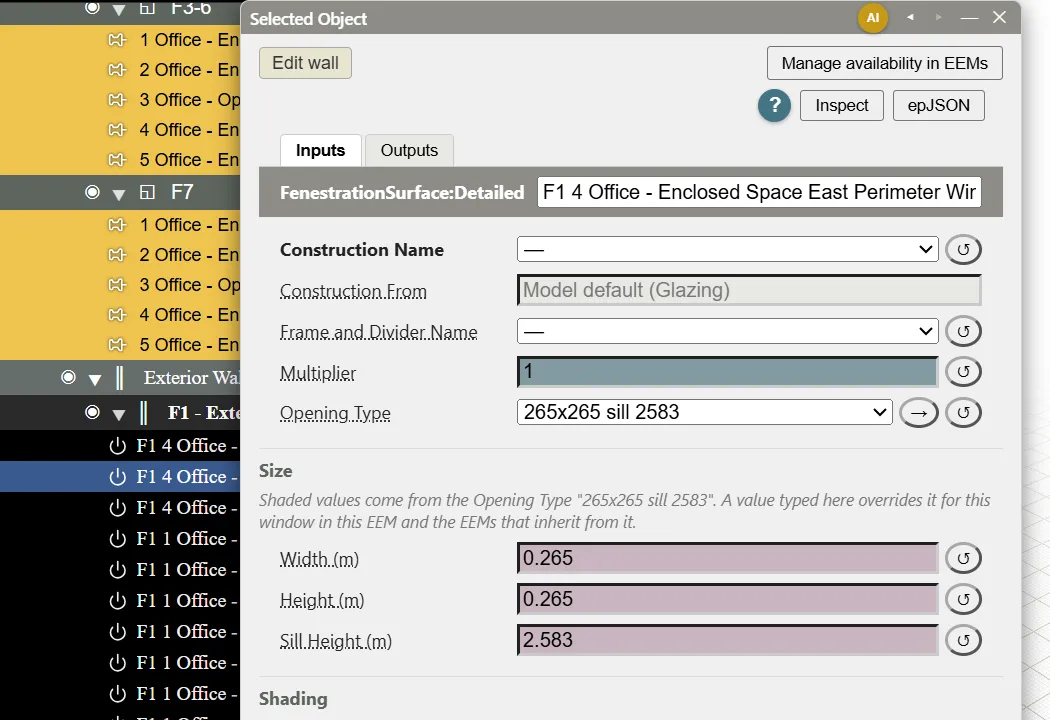
- For each window whose Opening Type is 265x265 sill 2583, select it in the list and press Delete. There are six: East Perimeter Window 2, North Perimeter Windows 2, 5, 8 and 11, and West Perimeter Window 2. Keep the shop windows (1585x2230) and the transom windows above them (955x965).
Second floor (F2). Here the traffic-signal arm and the street lamp hide the real windows, so all of F2’s windows from the photo are stray ones. The second floor has the same windows as the floors above, so the next section replaces them.
Give the second and top storeys the typical windows
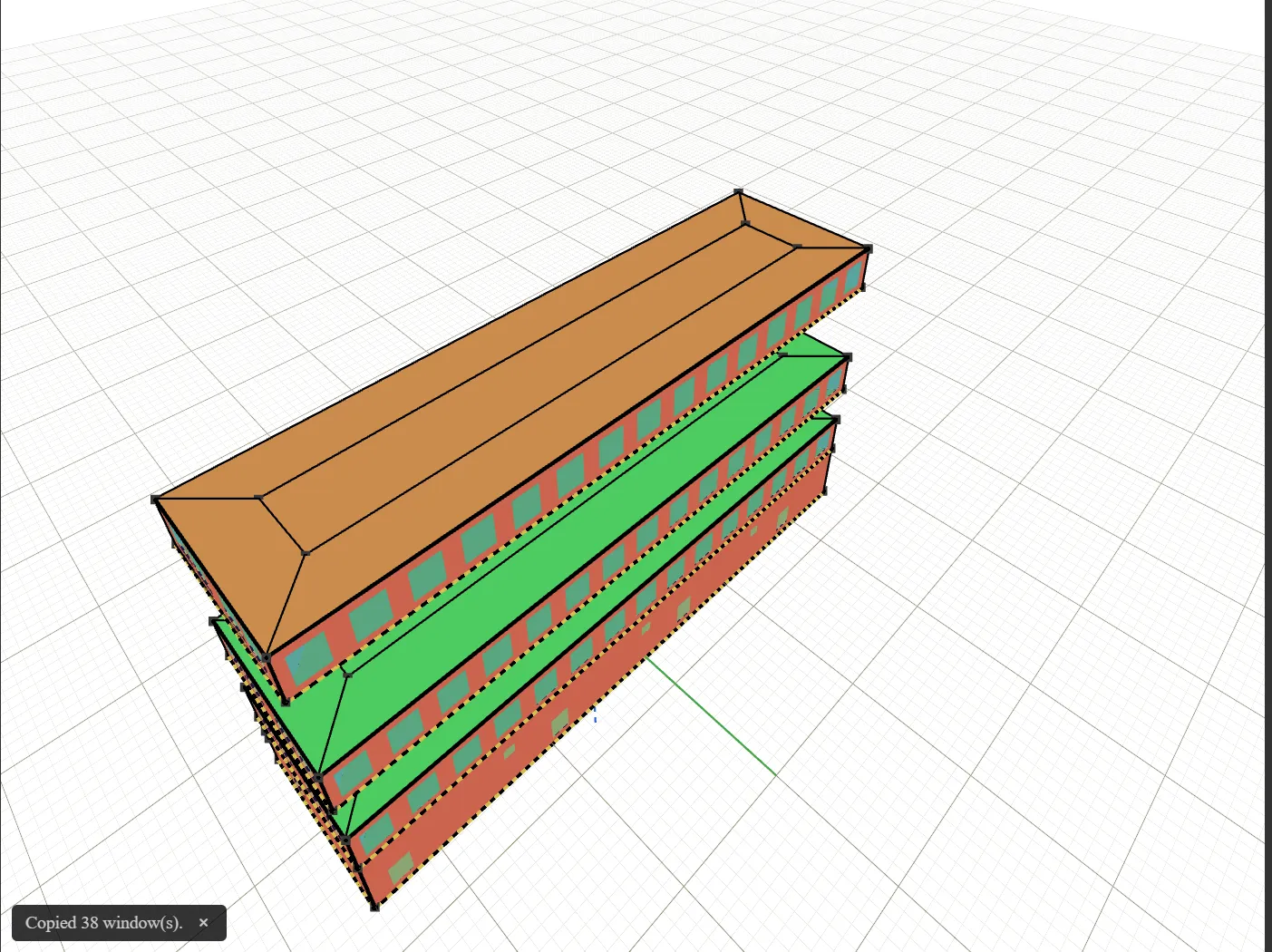
The cornice hides the top of the photo’s seventh storey, so that storey got no windows from the photo, and the second floor got only stray ones. Floors F3-6 have the building’s typical windows on every facade, so copy them to F2 and F7.
- In the Outliner, click F2 - Exterior Walls.
- Click Edit input fields for selected object(s) in the top toolbar.
- Under Copy Windows from Floor, choose F3-6 and click Copy Windows from Floor.
- EP3 asks “This wall has 28 windows shown in this EEM. What should happen to them?” Click Erase Them.
The status line reads “Copied 38 window(s).”
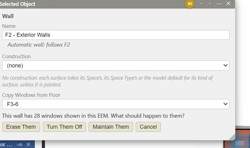
- Click F7 - Exterior Walls and do the same: choose F3-6 under Copy Windows from Floor and click Copy Windows from Floor. F7 has no windows, so EP3 copies the 38 windows without asking.
- Close the dialog and hide the photo with Hide ALL elevations (the eye on the Elevations row).
The Building now has 125 windows: the 83 from Create, less the 6 stray windows deleted on F1 and the 28 erased on F2, plus 38 copied to each of F2 and F7. They are the shop and transom windows on the ground floor and the typical office windows on floors 2 to 7.
- Save the model.
Check the model
- In the toolbar’s EEM list, choose PSZ-AC. This EEM holds the HVAC system, so check and simulate it rather than Global.
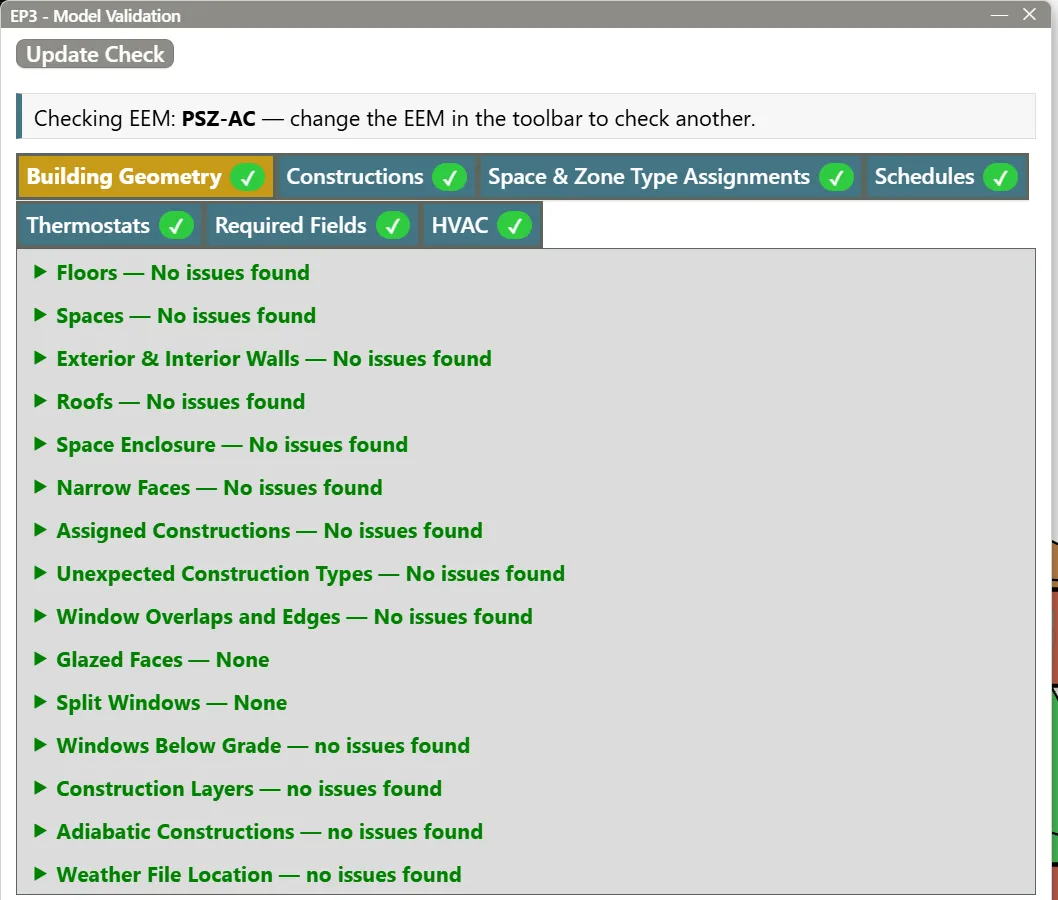
- Click Check the model for common issues.
EP3 - Model Validation checks the PSZ-AC EEM. Every tab shows a tick. On Building Geometry, Adiabatic Constructions finds no issues: the party wall has a construction with layers. Weather File Location finds no issues either, because Chicago Midway is less than 50 km from the site location the map saved.
- Close the dialog.
Run a simulation and look at the results
- Click Simulate your model in the top toolbar.
- In Simulate / Export, make sure only PSZ-AC (active) is ticked.
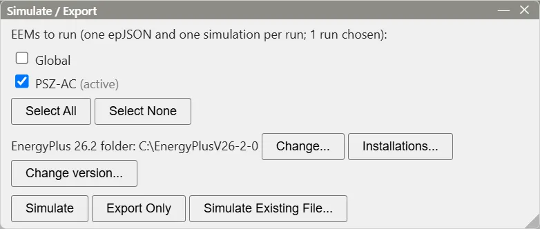
- Click Simulate. If EP3 asks for a run folder, choose your project folder.
The run takes about a minute. The line for the run then reads “FairbanksMorse_PSZ-AC Completed 0 fatal, 0 severe, 25 warnings”.
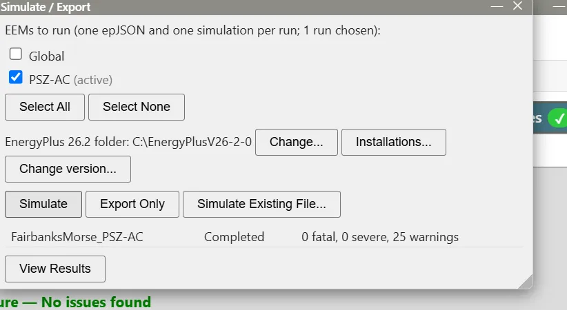
- Click View Results.
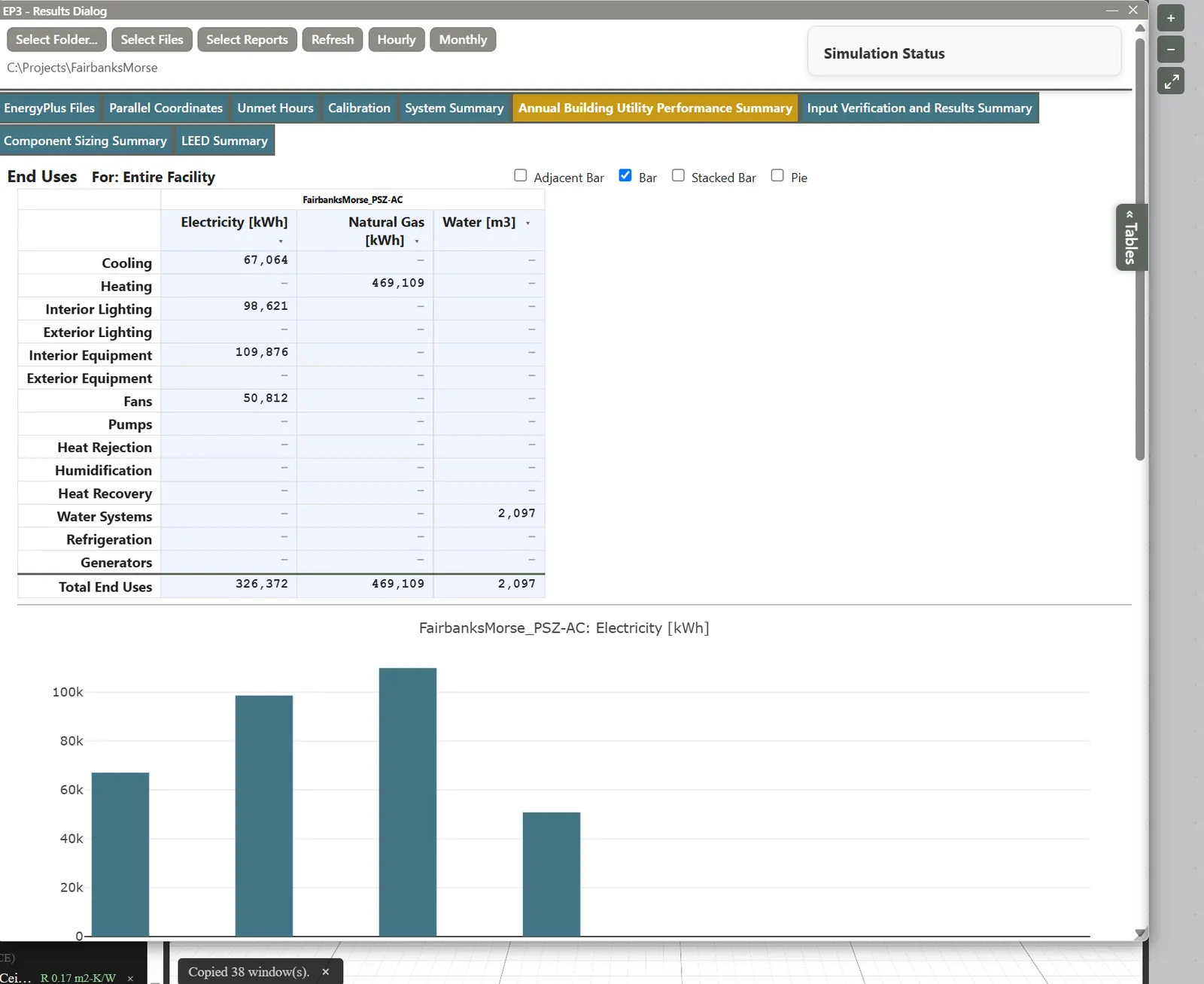
- Click the Annual Building Utility Performance Summary tab.
End Uses shows the year’s energy by use. In this run the building used 326,373 kWh of electricity (interior equipment, lighting, cooling and fans) and 469,109 kWh of natural gas for heating. Your figures can differ a little with your window picks and the neighbours EP3 added.
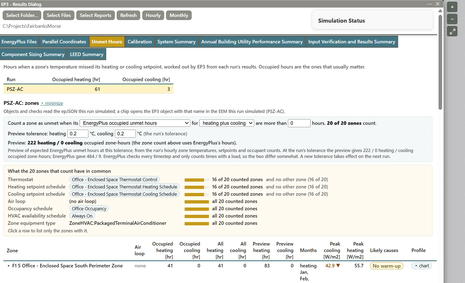
- Click the Unmet Hours tab.
The run left 61 occupied heating hours and 3 occupied cooling hours unmet. The zone table lists the zones with the most unmet hours first, and Likely causes suggests why, for example “No warm-up” on the perimeter zones on cold January and February mornings. A model of an existing building usually needs its schedules and system sizes checked against the real building next.
Next steps
- Every map setting, including adding more buildings later and moving the site: Buildings and Surroundings from Maps.
- Read the results in more depth: Running Simulations, and Viewing and Interpreting Results.
- Change a group of windows at once with its OpeningType: Windows, Shading, and Daylighting.
- Windows from Elevations with CAD drawings, and walls no drawing shows: Floors and Windows from CAD Drawings.
- What each Model Validation tab checks: Model Troubleshooting and Quality Assurance.